WebSphere Portal 5.x
Ops Guide
Contents
- Overview
- A basic Portal installation
- Three-tier
- Optimize response times with a reverse caching proxy
- A collaborative Portal
- Enhanced security Portal
- Tivoli Access Manager
- Netegrity SiteMinder
- Portal clustering
- The horizontal Portal cluster
- The vertical Portal cluster
- Decoupling from back-end systems
- The elaborated Portal cluster
- The elaborated security Portal cluster
- The Availability Gold Standard
- Pre-Install
- Production Portal Architectures
- Installation phase
- Network setup
- Install Web servers
- Install Load Balancer
- Install the back-end servers
- Verify prerequisites
- Password maintenance
- Proxy authentication with Content Access Service
- Enable Content Access Service
- Change the Portal database username and password
- Create a new database user
- Credential Vault
- How Credential Vault works
- Using Credential Vault
- Surfacing an application
- Manage security
- Integrating LDAP
- Performance considerations
- Using searchFilter to improve search performance
- Using searchBases to improve search performance
- Use LDAP connection pool to improve performance
- Increasing the groupCacheRefreshInterval
- Specific performance tips for Active Directory
- LDAP architecture and schema layout considerations
- Using an LDAP server cluster
- Using a single LDAP image
- LDAP, WebSphere Portal, and the Q/A environment
- LDAP administration
- Configuring WebSphere Portal for a read-only LDAP
- Understanding a J2EE Portal
- Portal configuration
- Moving from staging to production
- Deployment and build process
- Determining what to move
- Using the XMLAccess tool for moving
- The XML configuration interface
- Object IDs
- The Custom Unique Names portlet
- Transferring Portal artifacts using XMLAccess
- Transfer process
- Exporting a sample page using XMLAccess
- Exporting
- Importing
- A step-by-step guide
- Preparing the environment
- Defining a naming standard
- Set up the XMLAccess script
- Preparing the worksheet
- Example worksheet
- Run activities
- Verifying the prerequisites
- Using XMLAccess to export Portal artifacts
- Bundling the supporting files
- Transferring the bundle
- Distributing the supporting files to a single server
- Distributing the supporting files to a cluster
- Update the target configuration
- Post transfer actions
- Ensuring that the nodes are synchronized
- Restarting the server
- Activating the portlets
- Making any manual changes
- Customized portlets
- Portal settings
- Collaborative components
- How does customization and the transfer process work?
- Troubleshooting and best practices
- Change the host or domain name
- Change database servers
- Change LDAP servers
- Backup and recovery
- Maintaining a healthy Portal environment
- On Demand clustering solutions
- Temporarily removing a clustered node to apply maintenance
- The sample cluster production environment
- Performance tuning
- Understanding the environment
- Application server tuning
- Cross-platform tuning parameters
- Additional notes for an AIX environment
- Application server cloning
- Database server tuning
- IBM DB2 Enterprise Edition Database parameter tuning
- Oracle Enterprise Edition Database parameter tuning
- Other database considerations
- Directory server tuning
- Web server tuning tips
- Security filters
- Dereferencing aliases
- Operating system specific tuning parameters
- File Descriptors for UNIX systems
- Kernel parameters for Solaris platform
- Network tuning
- Solaris networking
- AIX networking
- Windows networking
- WebSphere Portal service properties
- XMLAccess tool
- Portal installation
- Basic Portal installation worksheet
- WebSphere Portal databases configuration, DB2 UDB fact sheet
- Oracle Fact Sheet
- Change the mode in WebSphere Portal
- Set read-only mode
- Set read or write mode
- Switch database servers
- Change from a DB2 database to another DB2 database
- Enable horizontal scaling with a dispatcher
- HTTP server
- WebSphere Portal
- Forward caching proxy
- Database server
- Directory server
Overview
Maintaining WebSphere Portal entails mastering integration with any or all of the following...
- Networks
- Databases
- WebSphere Application Server
- Back-end applications
- Business processes
- Web browsers
- Directory servers
- Web servers
- Reverse caching proxies
- Forward caching proxies
A basic Portal installation
       HTTP Server
           |
    WebSphere Portal
           |
          WPCP
           |
     Portal Search
           |
    Database Server
           |
    Directory Server
Three-tier
A three-tier architecture is created by running scripts to link with an HTTP server, a database server, and a directory server.
  ------------------------
  |    HTTP Server       |
  ------------------------
           |
  ------------------------
  |     Firewall         |
  ------------------------
           |
  ------------------------
  | WebSphere Portal     |
  |       WPCP           |
  |  Portal Search       |
  ------------------------
           |
  ------------------------
  |     Firewall         |
  ------------------------
           |
  ------------------------
  |   Database Server    |
  |   Directory Server   |
  ------------------------
The firewalls are optional.
Optimize response times with a reverse caching proxy
To optimize respone times, use groups of load-balanced reverse caching proxies to optimize response times for requests that come from the network into the Portal infrastructure. Responses to requests for static resources are cached.
Static resource stay unchanged for all users, regardless of the time slot. For example, if the content is static only for subseconds, but many users access it within this time slot, the resource is static. Reverse proxies can handle the following types of resources:
- Images
- JavaScript files
- Cascading style sheets
- Static HTML pages
- Servlet output
- Anonymous pages
The Web server conceptual node sets HTTP caching directives in HTTP responses that are sent to the reverse proxies.
A request to a full Portal page is always followed by a sequence of requests (typically, an average of 20 to 30 requests) to static resources for the static components (mainly images) imbedded into the page.
You can combine multiple reverse caching proxies.
The following figure illustrates how you can locate the caching proxy that WebSphere Portal uses to improve content delivery times and portal system utilization.
  ------------------------
  |    HTTP Server       |
  ------------------------
           |
  ------------------------
  |     Firewall         |
  ------------------------
           |
  ------------------------
  | WebSphere Portal     |
  |       WPCP           |
  |  Portal Search       |
  ------------------------
           |
  ------------------------
  |     Firewall         |
  ------------------------
           |
  ------------------------
  |   Database Server    |
  |   Directory Server   |
  ------------------------
This architecture comes available with WebSphere Edge Server and does not require additional hardware.
A collaborative Portal
The following figure shows the products and components that are important for setting up a collaborative Portal (Portal Extend).
  ------------------------
  |    Caching Proxy     |
  |       CBR            |
  ------------------------
           |
  ------------------------
  |  WebSphere Portal    |
  |       WPCP           |-------------
  |  Portal Search       |            |
  ------------------------            |
           |                          |
  ------------------------            |
  |     Firewall         |            |
  ------------------------            |
           |                          |
  ------------------------            |
  |   Database Server    |            |
  ------------------------            |
           |                          |
  ------------------------  ------------------------
  |      Domino          |--|   Sametime           |
  |   Directory Server   |  |   Quickplace         |
  ------------------------  ------------------------
Enhanced security Portal
Tivoli Access Manager
IBM Tivoli Access Manager is a policy-based access control solution that provides a self-protecting environment by:- Delivering a unified authentication and authorization for e-business initiatives as you secure a single enterprise or a federated environment
- Preventing unauthorized access by using a single security policy server to enforce security across multiple file types, application providers, devices, and protocols
- Maintaining password and user integrity using single sign on
- Discovering problems or potential problems using robust auditing and information-gathering tools
Here is our architecture with TAM included...
  ------------------------  ------------------------
  |    Security Proxy    |--|    Security Server   |
  ------------------------  ------------------------
           |
  ------------------------
  |     Firewall         |
  ------------------------
  ------------------------
  |    HTTP Server       |
  ------------------------
           |
  ------------------------
  |     Firewall         |
  ------------------------
           |
  ------------------------
  | WebSphere Portal     |
  |       WPCP           |
  |  Portal Search       |
  ------------------------
           |
  ------------------------
  |     Firewall         |
  ------------------------
           |
  ------------------------
  |   Database Server    |
  |   Directory Server   |
  ------------------------
Netegrity SiteMinder
You can also use WebSphere Portal with Netegrity SiteMinder as an external security manager. SiteMinder enables you to administer and consistently enforce user access to Web applications by providing Single Sign On (SSO) to users. Similar to Tivoli Access Manager, SiteMinder provides the following:
- Centralized, policy-based control of user authentication and authorization management
- SSO to an enterprises' Web applications
- Enterprise-class manageability
- Secure, standards-based federation security services
- Enterprise-class scalability and high availability
- Extensive support for heterogeneous IT environments
- Comprehensive audit and reporting services
- Comprehensive password management services
- Role-based access control
In the following figure, WebSphere Portal and SiteMinder split security responsibilities by externalized security management (authentication and authorization).
  ------------------------  ------------------------
  |    HTTP Server       |--|    Security Server   |
  |    Security Plugin   |  ------------------------
  ------------------------
           |
  ------------------------
  |     Firewall         |
  ------------------------
           |
  ------------------------
  | WebSphere Portal     |
  |       WPCP           |
  |  Portal Search       |
  ------------------------
           |
  ------------------------
  |     Firewall         |
  ------------------------
           |
  ------------------------
  |   Database Server    |
  |   Directory Server   |
  ------------------------
Portal clustering
WebSphere Portal is integrated with and uses the WebSphere Application Server (WAS) middleware. The middleware allows you to use multiple strategies for scaling and can be scaled vertically and horizontally. With both scaling concepts, the number of servers running the application is increased.
Vertical scaling refers to the concept of cloning an application onto a single node. You can use vertical scaling to fully use a node within the conceptual node group in the case where resource congestions or locking conditions prevent a single application instance to scale up to the nodes limit.
Horizontal scaling refers to the concept of increasing the number of nodes on which the appservers are running. You can use horizontal scaling in cases where all nodes within the cluster are fully used.
You can use vertical clustering to achieve better tolerance against malfunctioned applications that make the server process fail. In this case, other processes running on the same node are still able to serve other requests. However, the possibility of the same error causing other server processes to fail is high. Vertical cloning cannot accommodate for hardware failure.
You can use horizontal clusteringto accommodate for software or hardware failures. If any conceptual node within the conceptual node group fails, other conceptual nodes within the conceptual node group can handle their workload. With both vertical and horizontal clustering, take care to avoid data loss due to conceptual node failures. If data needs to be available even after conceptual node failures, this data needs to be persisted into a database or shared between multiple nodes in memory. This caution is in particular important for session data. Session data take over between conceptual nodes can only happen if the cluster is configured accordingly.
The horizontal Portal cluster
A horizontal Portal cluster provides fault-tolerance of Portal nodes as well as additional capacity. In this environment, scalabilty requires another machine to run the Deployment Manager.
The following figure illustrates the WAS clustering capabilities. You can have an arbitrary number of nodes.
          ------------------------  -----------------------
          |    HTTP Server       |  |  Deployment Mgr    |
          ------------------------  ----------------------
                                  |
                         ------------------------
                         |     Firewall         |
                         ------------------------
                                  |
  ------------------------  ------------------------ ------------------------
  | WebSphere Portal     |  | WebSphere Portal     |  | WebSphere Portal     |
  |       WPCP           |  |       WPCP           |  |       WPCP           |
  |  Portal Search       |  |  Portal Search       |  |  Portal Search       |
  ------------------------  ------------------------ ------------------------
                                  |
                         ------------------------
                         |     Firewall         |
                         ------------------------
                                  |
                         ------------------------
                         |   Database Server    |
                         |   Directory Server   |
                         ------------------------
The vertical Portal cluster
A vertical Portal cluster provides additional scalability if you cannot drive your node CPU load on one server instance. This environment provides process failure tolerance.
Decoupling from back-end systems
You can decouple back-end systems by using forward caching proxies which reduce latency due to back-end access using a cachable protocol. Forward caching proxies tie into an existing environment to optimize the application running over the network. In this environment, cache can use data sharing, thus reducing bottlenecks.
  ------------------------
  |    HTTP Server       |
  ------------------------
           |
  ------------------------
  |     Firewall         |
  ------------------------
           |
  ------------------------  ------------------------
  | WebSphere Portal     |  |                      |
  |       WPCP           |--|  Caching Proxy       |
  |  Portal Search       |  |                      |
  ------------------------  ------------------------
           |
  ------------------------
  |     Firewall         |
  ------------------------
           |
  ------------------------
  |   Database Server    |
  |   Directory Server   |
  ------------------------
The elaborated Portal cluster
The elaborated Portal cluster is a typical fault tolerant Portal cluster where caching is typically used. This solution avoids a signal-point-of-failure with redundancy across the board. Each Portal is running in a different physical location (in this example, one in Raleigh and one in Charlotte). Only one directory server and database server is active at one time. Support 24x7 can also be used.
          ------------------------  -----------------------
          |    Dispatcher        |  |  Dispatcher        |
          ------------------------  ----------------------
                                  |
          ------------------------  -----------------------
          |    Caching Proxy     |  |  Caching Proxy     |
          |        CBR           |  |      CBR           |
          ------------------------  ----------------------
                                  |
          ------------------------  -----------------------
          |    HTTP Server       |  |  Deployment Mgr    |
          ------------------------  ----------------------
                                  |
                         ------------------------
                         |     Firewall         |
                         ------------------------
                                  |
  ------------------------  ------------------------  ------------------------
  | WebSphere Portal     |  | WebSphere Portal     |  | Deployment Mgr       |
  |       WPCP           |  |       WPCP           |  ------------------------
  |  Portal Search       |  |  Portal Search       |
  ------------------------  ------------------------
                                  |
                         ------------------------
                         |     Firewall         |
                         ------------------------
                                  |
                         ------------------------
                         |   Database Server    |
                         |   Directory Server   |
                         ------------------------
The elaborated security Portal cluster
With an elaborated security Portal cluster, the Portal cluster adds a security server (either Tivoli Access Manager or SiteMinder) providing 24x7 security operation. In addition, a Signal Sign On environment can exist without having to logon more than once. This Portal architecture avoids a single-point-of-failure and makes use of caching and enhanced security. The location of security proxies allows for protection of cached content.
Note: Cachable content can be protected by its own security manager.
          ------------------------  -----------------------
          |    Dispatcher        |  |  Dispatcher        |
          ------------------------  ----------------------
                                  |
          ------------------------  -----------------------
          |    Security Proxy    |  |  Security Proxy    |
          ------------------------  ----------------------
                                  |
          ------------------------  -----------------------
          |    Dispatcher        |  |  Dispatcher        |
          ------------------------  ----------------------
                                  |
          ------------------------  ----------------------- -----------------------
          |    Caching Proxy     |  |  Caching Proxy     |  |  Security Server   |
          |        CBR           |  |      CBR           |  ----------------------
          ------------------------  ----------------------
                                  |
          ------------------------  -----------------------
          |    HTTP Server       |  |  Deployment Mgr    |
          ------------------------  ----------------------
                                  |
                         ------------------------
                         |     Firewall         |
                         ------------------------
                                  |
  ------------------------  ------------------------  ------------------------
  | WebSphere Portal     |  | WebSphere Portal     |  | Deployment Mgr       |
  |       WPCP           |  |       WPCP           |  ------------------------
  |  Portal Search       |  |  Portal Search       |
  ------------------------  ------------------------
                                  |
                         ------------------------
                         |     Firewall         |
                         ------------------------
                                  |
                         ------------------------
                         |   Database Server    |
                         |   Directory Server   |
                         ------------------------
The Availability Gold Standard
The Availability Gold Standard allows WebSphere Portal to run on two sets of clustered machines. This Portal architecture allows you to operate in a 24x7 environment while maintaining easy configuration and maintenance procedures. This is both an active and a passive configuration. The other side is used as a warm backup.
WebSphere Portal is architecturally designed for continuous operation scenarios and additional fault tolerance.
Pre-Install
WebSphere Portal for Multiplatforms is not a single product. Instead, it is a software solution that contains multiple components. Depending on the architecture and topology, the installation task requires different skills and expertise. For example, installing a large Portal environment usually requires the efforts of the Portal server administrator as well as an IT architect, a database administrator (DBA), a security specialist, a Lightweight Directory Access Protocol (LDAP) specialist, and infrastructure (operating systems and networking) administrators. The Portal administrator must gather the required information and documentation for the installation and must also coordinate the team of experts when preparing to build production Portal environments.
A high-level overview of a roadmap for a production Portal server installation includes two phases:
- Plan phase
- Understanding the basic technology and components of the Portal
- Specifying any requirements
- Defining the topology and planning the capacity
- Review installation prerequisites and latest news
- Plan for the integration of back-end servers
- Compiling installation documents
- Preparing for preinstallation activities
- Install phase
- Setting up the infrastructure
- Install the basic configuration for WebSphere Portal
- Install the Network Deployment server
- Install Web servers and Load Balancer
- Applying fixpacks and fixes
- Install the back-end servers
- Creating and configuring the Portal clusters
Production Portal architectures
Example architecture:

While planning the installation, the Portal administrator should assure compatibility and the support level for the entire environment, depending on feedback from other administrators. After completing the planning phase, the Portal administrator can launch the installation phase based on the documents produced during the planning phase, guarantying that the required installation information is available.
Step 1. Understanding the basic technology and components of the Portal
Understanding the Portal technology and components before you begin the planning and installation phases is critical. You should have a knowledge of key Portal concepts, such as single sign-on, security, directory services, content management, collaboration, search and taxonomy, support for mobile devices, accessibility support, and internationalization. If you are not familiar with Portal technology, review the following basic Portal documents:
- Guide to WebSphere Portal 5.0
- IBM WebSphere Portal for Multiplatforms V5 Handbook, SG24-6098, Chapters 1 and 2
- WebSphere Portal InfoCenter, Product Overview section
Step 2. Specify requirements
Portals are a central point of access that encapsulate several components and functions. Before you begin the installation, conduct a thorough review with user representatives and IT architects to define functionality and performance objectives for the Portal.
Portal functions may include both WebSphere Portal functions and also external legacy systems. WebSphere Portal includes features such as Collaboration, Personalization, Extend Search, Click-to-Action, Translation, Single Sign On, Content management, and many others.
The logical design and software components for both the staging and production Portals include:
- Support for an external user registry running on database manager systems (for example, Oracle and DB2�)
- A user directory running on an LDAP-compliant component (for example, IDS and Sun ONE)
- WebSphere Portal Extend Edition V5.0.2.1
- Support for Load Balance component (Edge Server)
- Support for remote Web servers (IBM HTTP Server)
- Support for WebSphere Portal application clustering (WAS Network Deployment)
Step 3. Defining the topology and planning the capacity
Deploying a production Portal differs from other environments mainly because the deployment needs to happen as fast as possible in a highly controlled environment. Availability, stability, and performance are the main concerns for Portal administrators by the time a production Portal is designed. The business users of the Portal and the solution architect need to evaluate these concerns and to define clip levels. The criteria that you use for such definitions can vary according to the main objectives for your Portal environment.
A simple checklist on performance parameters that consider when you define the specification are:
- The number of concurrent users
- The page views per second
- The average CPU usage per server
- Response time
Review the following WebSphere Portal documentation before continuing:
- Portal library page
- Guide to WebSphere Portal 5.0 document.
- IBM WebSphere Portal for Multiplatforms V5 Handbook, Chapter 3
This document discusses a four-tier design, using horizontal clustering, that includes layers for load balancing, Web servers, appservers, Portal servers, and a database server. Clustering applies to the Web server, application server, and Portal server layers. Remote Web servers running WAS plug-ins perform the first level of load balancing. Another level of load balancing is implemented by a front-end Load Balance server (Edge Server).
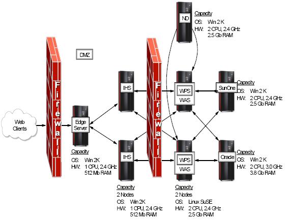
The output for this step is a set of documents that depicts the details for the logical and physical design of the Portal solution. Hardware capacity, software components, and network configuration should be included in this set of documents. For a sample topology and capacity Portal cluster for Linux.
Databases and LDAP directories are most commonly managed by their own administrators. Thus, Portal administrators should communicate the Portal solution requirements in terms of database instances and directory configurations to these administrators. See Appendix B, Portal installation worksheets and samples for sample forms and worksheets that you can use to clarify the workflow between the Portal and back-end server administrators.
Step 4. Review installation prerequisites and latest news
After reviewing the logical and physical design, Portal administrators must ensure that all components included in the Portal solution are supported. In addition, check and verify any required upgrades to the software components. See the document listing the latest supported hardware and software.
You should also review the Release Notes for the WebSphere Portal edition that you are using in the Portal solution.
Step 5. Plan for the integration of back-end servers
To integrate WebSphere Portal with back-end servers, such as database and LDAP servers, the production Portal must have a database manager and an LDAP directory running outside the Portal server machine for performance reasons. Thus, create and tune a database and directory infrastructure on which the Portal application will rely.
To install a database and LDAP server on dedicated machines, :
- Install the database and LDAP server on dedicated machines if they are not currently installed or available.
- Create and configure the Portal databases on the database server.
- Install the database client code at the Portal machine and validate communication with the database server.
- Add the Portal users and groups to the LDAP directory.
- Establish and test communication between the Portal, database, and LDAP servers.
- Run the Portal configuration tasks.
Some of these steps require specific skills, most commonly provided by the database and the LDAP administrators. Nevertheless, the Portal administrator still needs to specify and communicate Portal requirements to these administrators.
To help simplify the process, se Appendix B, Portal installation worksheets and samplesa. These worksheets are customized for database (DB2 and Oracle) and LDAP (IDS and Sun ONE) configurations. These forms are quick snapshots of the information that is described in the database and LDAP installation sections of the WebSphere Portal InfoCenter.
Each form is made of two sections. Update the first section by completing the parameters in the Value column. Then, communicate this information to the database and LDAP administrators. This installation worksheet contains the necessary data for the database and LDAP administrators to accomplish their infrastructure settings task. These administrators return the second form after the infrastructure settings task is complete. You need the data that the second form contains to perform the Portal configuration steps.
Step 6. Compiling installation documents
Before you install WebSphere Portal, be sure to collect all the required information, documents, and installation parameters from the worksheets available in Appendix B, Portal installation worksheets and samples. Completing the worksheets will help you anticipate any possible misconfiguration issues and avoid Portal installation failures.
Step 7. Preparing for preinstallation activities
It is necessary that you apply several fixes from different sources to accomplish the full WebSphere Portal V5.0.2.1 installation. Table 2-1 lists the fixes, patches, and maintenance packages that we used in the installation phase of this chapter.
Sources Available at
| Windows� 2000 service packs | http://www.microsoft.com/windows2000/downloads/servicepacks/default.asp |
| AIX maintenance page | http://www-912.ibm.com/eserver/support/fixes/fcgui.jsp |
| WAS support | http://www-306.ibm.com/software/webservers/support.html |
| WebSphere Portal Server support | http://www-306.ibm.com/software/genservers/portal/support/ |
Installation phase
Ports
Port WAS Portal HTTP Transport 9080 9081 HTTPS 9443 9444 HTTP Administrative Console 9090 9091 HTTP Administrative Console Secure 9043 9044 Internal JMS Server 5557
JMS Server Queued Address 5558
Bootstrap 2809 9810 SOAP Connector 8880
DRS Client Address
You can identify those ports that are listed on the server by using the netstat command:
- On Windows servers
netstat -an | find �LISTEN�
- On Linux servers
netstat -an | grep LISTEN | grep tcp
- On AIX servers
netstat -an | grep LISTEN
With the second scenario, where you are installing a new instance of the operating system, make sure that you install the appropriate version of the operating system and patches. You should also install utilities that will be useful during the Portal installation, such as a tool that extracts files from zipped files, remote access tools, FTP servers, and so on.
In the staging server, we installed the following Windows 2003 Server Standard Edition components:
- Windows 2003 Server Standard
- A tool that extracts files from zipped files
- Support for terminal services client and remote desktop
We did not install patches in the staging server.
Note: For remote installation on Windows 2003 boxes, Windows 2003 automatically enables Terminal Services. However, configure Remote Desktop before a terminal services client will connect to the server. To do so, right-click the My Computer icon and select Properties. Select the Remote tab and enable Remote Desktop by clicking Allow users to connect remotely to this computer.
In the Web servers, we installed the following Windows 2000 components:
- Windows 2000 Advanced Server
- Service Pack 4
- A tool that extracts files from zipped files
Verify your Windows version by right-clicking the My Computer icon and selecting the General tab in the System properties panel.
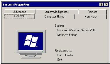
In the production servers, we installed the following editions of AIX and Linux:
For AIX
- AIX V5.2.
- Maintenance Level 02
- APAR IY43952
Verify the AIX version and patches that are applied by running...
For Linux
- SUSE SLES Linux for Intel� V8.2
- No patches applied
Verify the Linux version and kernel release...
Note: Before proceeding, assure that the system clock for each server is synchronized to the same hour and minute time stamp.
Administrator user
In Windows 2000 and 2003, grant the administrator user ID specific privileges before you run the Portal installer. Make sure that the administrator user ID is allowed to:- Act as part of the operating system
- Log on as a service
Control Panel | Administrative Tools | Local Security Policy | Security Settings | Local Policies | User Rights Assignment
Storage and file system
WAS and the WebSphere Portal server require a large amount of disk space. Thus, allocate the necessary storage.
Review the prerequisites available from the WebSphere Portal InfoCenter for an updated list of the minimum storage requirements for the Portal server:
Windows servers administrators need only to verify the total available amount of disk storage and to assure that the minimum space requirements are satisfied. We encourage UNIX� administrators to create separate file systems for WAS and WebSphere Portal. Linux administrators should pay special attention to the size of the swapping partition, which must be at least as big as the physical memory of the server. Small swapping partitions slow down the server so much that the Portal installer will fail during basic Portal setup.
Network setup
Network configuration is required to allow the Portal installer to run without failures. Each server included in the Portal solution is required to hold a static IP address, to have a fully qualified domain name, and to belong to the same domain as all other servers for single sign-on purposes.
Network setup validation is essential and is required before the Portal installer is run. Verify the Windows 2000 and 2003 servers network configuration by selecting
Start | Settings | Network and Dial-Up Connections | Enabled (Right-click) | Properties | TCP/IP Properties
Also, verify that the domain name is correctly defined using the ipconfig command.
C:\Program Files\Administrator > ipconfig /all

Windows 2000 IP Configuration
Host Name . . . . . . . . . . . . . .: devportal
Primary DNS Suffix . . . . . . . : redbook.ibm.com
Verify the AIX network configuration by running the following command:
# smitty tcpip
On the TCP/IP menus, select Minimum Configuration and Startup. Then, move the cursor to the main network interface and press Enter.
Verify the Linux network configuration by running the YasT Control Center utility. To do so, select...
Yast2 Modules | Network Devices | Network card | Change
On the list of available cards, select the current enabled interface and click Edit.
In this window, select Host name and name server and verify the host and domain names.
Important: If you are using a firewall to restrict TCP/IP connections among the servers, then validate that the required communication ports between the Portal server and all other servers are active. The telnet command is the fastest way test these communication ports. If the firewall is configured correct, an error is not echoed back when you use the telnet command. Also, make sure that no firewall software is running on the Portal server during the Portal installation.
Step 2. Install the basic configuration for WebSphere Portal
You can run the Portal installer in three different modes:- Graphical User Interface (GUI) mode
- Text console mode
- Silent installation mode
A silent installation is suitable for production environments where you will install several instances of Portal server. Based on response files, customize only a few parameters that change from server to server (for example, host name) before you launch the next run of the Portal installer.
Another advantage of a silent installation is that the installation facts are documented in text files that you can add to the server�s documentation folder. You should load binary images of the Portal CDs into a disk drive that is shared by all the servers where the Portal installation will be run. A sample response file for Portal installation on Windows 2000 is available in Appendix B, Portal installation worksheets and samples.
Note: Support for Windows 2003 was introduced in WebSphere Portal V5.0.2. You should review the WebSphere Portal V5.0.2 installation readme file for installation instructions, because Windows 2003 installation is slightly different from other platforms.
publib.boulder.ibm.com/pvc/wp/502/ent/en/readme/install_win2003.html
Some versions of Java can report Windows 2003 incorrectly. For more information, see Technote 1173948
Before you run the installation procedure, make a backup copy of the vpd.properties file. In case manually uninstall the Portal server (for example, due to a Portal installation failure), you can use the backup copy of this file instead of manually editing it to remove Portal server entries from the installed software index.
Here are the locations of the vpd.properties file...
Operating System Location Linux /vpd.properties or /root/vpd.properties AIX /usr/lib/objrepos/vpd.properties Windows C:\WINNT\vpd.properties
Because of the small number of servers installed on the staging and production servers, we used the GUI mode for the Portal installation on these servers. We used the procedures in IBM WebSphere Portal for Multiplatforms V5 Handbook to accomplish the basic Portal configuration installation (see 2.3, �Portal documentation� on page 63).
After completing the basic installation, verify that no failures occurred by reviewing the installation log files. (See �Verifying Portal installation log files� on page 246 for a detailed description on reviewing these files.) For this document, we followed the instructions available in Chapters 5 and 6 in IBM WebSphere Portal for Multiplatforms V5 Handbook.
Step 3. Install the Network Deployment server
To install WebSphere Network Deployment Server (Base), follow these steps:- Login to the server to be used as your Network Deployment server as an administrative user (for example, root).
- Mount the WAS Network Deployment CD to /cdrom.
- Run LaunchPad.sh from \cdrom\wasnd\linux\linuxi386 (Linux) or \cdrom\wasnd\aix\aix (AIX) and follow the instructions that appear.
- Make sure that you select all features for installation.
- Accept the default installation path for installation.
- Accept the default settings for NodeName, HostName, and CellName. Be sure that HostName contains the fully qualified domain name of the server. If not, update it manually with the server�s fully-qualified domain name.
- When the installation finishes, check the installation log file named log.txt at /WebSphere/DeploymentManager/logs for errors or exceptions. Be sure that the following message appears in the log file: INSTFIN: The WebSphere 5.x install is complete
To install the WAS Network Deployment Enterprise components, follow these steps:
- Mount the WAS Enterprise CD to /cdrom.
- Run LaunchPad.sh from \cdrom\was\linux (Linux) or \cdrom\was\aix (AIX) and follow the instructions that appear.
- Make sure to select the Add option to the existing copy of WAS Network Deployment V5.x.
- When the installation finishes, check the installation log file named WAS.PME.install.log at /WebSphere/DeploymentManager/logs for errors or exceptions. Be sure that the following message appears in the log file: The InstallShield Wizard has successfully installed IBM WAS.
Step 4. Install Web servers and Load Balancer
For production Portals, the integration of HTTP servers must handle the client HTTP requests. For details on the Portal configuration procedure for external remote Web servers, refer to the following:
http://publib.boulder.ibm.com/pvc/wp/502/ent/en/InfoCenter/wpf/inst_ihs.html
Install Web servers
Before you configure the Portal, install the Web servers by following these steps:
- Login to the server intended for the Web HTTP services using the Administrator id. This procedure assumes IHS 1.3.26 running on Windows 2000 SP4.
- Run install.exe from Portal cd1-1.
- Select Custom for the setup type and click Next.
- Disable all components and select IBM HTTP Server 1.3.26. Select Yes, Web Server Plugins - IBM HTTP Server.
- Verify the installation path and click Next in the summary panel.
- Wait until the installation finishes and click Finish.
- Verify the installation by loading the IHS welcome page at: http://localhost
Install Load Balancer
The load balancing tool that we used in the production Portal server is WebSphere Edge Server V5.0 for Windows 2000. This product is included in WebSphere Portal Server V5.0.2 package. To install the load balancer, follow these steps:
- Login to the server intended for the load balancing services using the Administrator id. (This procedure assumes that Edge Server V5.0 is running on top of Windows 2000 SP4.)
- Run setup.bat from Portal cd1-21. See directory \wasedge\win.
- Select the Language for the installation program and click Next in the first panel.
- Select Install and click Next in the following window.
- Read the agreement, select I accept the terms in the license agreement, and click Yes.
- Select Load Balancer and Documentation from the components list and click Next.
- Click Finish in the summary panel.
- Wait until the installation finishes and click Finish. The server will reboot automatically.
- Verify the installation by reviewing Windows services list and assuring that the new service IBM Dispatcher is registered and successfully started.
For further details on the installation procedures, refer to:
http://www-306.ibm.com/software/webservers/appserv/doc/v50/ec/infocenter/edge/concepts.htm
After the base code installation, you also need to configure the Dispatcher to enable the load balancing between the two installed Web servers. To configure the Dispatcher:
- Start all the Web servers.
- On the Network Dispatcher server, select...
Start | Programs | IBM WebSphere | Edge Components | Load Balancer | Load Balancer.
- Expand Load Balancer.
- Right-click Dispatcher and select Start Configuration Wizard.
- Click Next on the welcome pages.
- Click Create Configuration.
- Select the item corresponding to your host from the drop-down list and click Update Configuration & Continue.
- Enter the cluster host name (for example, lincluster.redbook.ibm.com�) and click Update Configuration & Continue.
- Verify that the cluster host name was added and click Next.
Note: This is the host name of the fully-qualified domain name that will be used to access the Portal cluster.
- Choose Port 80 and click Update Configuration & Continue.
- Verify that the port was added and click Next.
- Click Add server.
- Enter the first HTTP server name.
- Repeat the process and add the second HTTP server.
- Click Update Configuration & Continue.
- Choose Yes and click Update Configuration & Continue.
- Click Next.
- Choose Windows 2000 and click View Loopback Instructions.
- Review the directions and click Next.
- Click Exit and the cluster configuration is done.
You also need to create and configure the loopback adapter with the following properties in each Web server:
- Static IP Address
- IP address = cluster IP address (for example, the IP address of the server running Edge Server V5.0)
- SubNet Mask = 255.0.0.0
- DNS configuration
- Preferred DNS server = local IP address
- No gateway
You can verify the Edge Server settings by loading the welcome HTTP server from each Web server individually. Assure that only one Web server is started and load a browser with the cluster HTTP page (for example, lincluster.redbook.ibm.com). You should also load the HTTP server home page.
Install the back-end servers
Two kinds of back-end servers are most commonly used in production systems: database and LDAP servers. Because Cloudscape� is not supported for production, install a more robust database server. The options that we considered for this document were DB2 UDB Enterprise and Oracle Enterprise Server. For the LDAP service, we chose IBM Directory Server and Sun ONE Directory Server.
- Install - LDAP
- Install - Database
- IBM WebSphere Portal for Multiplatforms V5 Handbook, Chapter 7
- Guide to configuring a WebSphere Portal V5 cluster
Note: For cluster environments, the database configuration task is not the same for all Portal nodes. Review the following documents before you integrate the Portal nodes to the same database instance:
Verify prerequisites
After the installation of the LDAP server, verify the LDAP service and the creation of Portal users by running an LDAP client tool such as ldapsearch.
C:\Documents and Settings\Administrator>ldapsearch -h ldap.redbook.ibm.com -D
uid=wpsadmin,cn=users,ou=aixcluster,o=redbook -w itso -b
ou=aixcluster,o=redbook "uid=wpsadmin"

uid=wpsadmin,cn=users,ou=aixcluster,o=redbook
givenName=wps
uid=wpsadmin
objectclass=inetOrgPerson
objectclass=organizationalPerson
objectclass=person
objectclass=top
objectclass=ibm-appuuidaux
sn=admin
cn=wps admin
ibm-appuuid=694df9c0-e6fa-11d8-8441-829741125cb3

C:\Documents and Settings\Administrator>ldapsearch -h ldap.redbook.ibm.com -D
uid=wpsadmin,cn=users,ou=aixcluster,o=redbook -w itso -b
ou=aixcluster,o=redbook "cn=wpsadmins"

cn=wpsadmins,cn=groups,ou=aixcluster,o=redbook
objectclass=groupOfUniqueNames
objectclass=top
cn=wpsadmins
uniquemember=uid=wpsadmin,cn=users,ou=aixcluster,o=redbook
You can verify the database server infrastructure from the Portal server machine only if the DBA has installed a client tool. (A client tool is mandatory for DB2 but not for Oracle.)
# su - db2inst1
$ db2 list node directory

Node Directory

Number of entries in the directory = 1

Node 1 entry:
Node name = PORTNODE
Comment =
Directory entry type = LOCAL
Protocol = TCPIP
Hostname = db.redbook.ibm.com
Service name = db2c_DB2

$ db2 list database directory

System Database Directory

Number of entries in the directory = 3

Database 1 entry:

Database alias = WPCP50
Database name = WCP502DB
Node name = PORTNODE
Database release level = a.00
Comment =
Directory entry type = Remote
Catalog database partition number = -1


Database 2 entry:

Database alias = FDBK50
Database name = FDK502DB
Node name = PORTNODE
Database release level = a.00
Comment =
Directory entry type = Remote
Catalog database partition number = -1


Database 3 entry:

Database alias = WPS50
Database name = WP502DB
Node name = PORTNODE
Database release level = a.00
Comment =
Directory entry type = Remote
Catalog database partition number = -1
Step 7. Creating and configuring the Portal clusters
You can use the following installation document for the Portal cluster configuration:www-106.ibm.com/developerworks/websphere/library/techarticles/0401_lamb/lamb2.htmlIf you get multicast errors after installation, see...
www-1.ibm.com/support/docview.wss?rs=688&uid=swg21167496
Password maintenance
Password maintenance is an important issue regarding production Portal servers. The following sections present an discuss of credentials (either user-password pairs or electronic certificates) that can be used by portal.
Proxy authentication with Content Access Service
Content Access Service is part of the Portlet Service Registry. It is available to portlet developers to establish connections to external content beyond the network firewalls through a proxy server. This service is available for both authenticated and non-authenticated proxy servers. To enable the service, the Portal administrator must update the service configuration properties file and add a credential to the credential vault slot within the Default Vault Segment.
Enable Content Access Service
Perform the following steps to enable Content Access Service:
- Edit...
$WP_ROOT/shared/app/config/services/PortletServiceRegistryService.properties.
- Update the proxy.http.* and proxy.https.* properties with the IP address and port number of the proxy server. (Update https only if SSL support is enabled in the proxy server.)
- Add proxy.auth.* properties to the properties file
#
# the name of the http proxy host
#
com.ibm.wps.pe.pc.legacy.service.ContentAccessServiceImpl.proxy.http.host=9.42.170.155

#
# the name of the http proxy port
#
com.ibm.wps.pe.pc.legacy.service.ContentAccessServiceImpl.proxy.http.port=3128
com.ibm.wps.pe.pc.legacy.service.ContentAccessServiceImpl.proxy.https.host=9.42.170.155
com.ibm.wps.pe.pc.legacy.service.ContentAccessServiceImpl.proxy.https.port=3128
com.ibm.wps.pe.pc.legacy.service.ContentAccessServiceImpl.proxy.auth.enabled=true
com.ibm.wps.pe.pc.legacy.service.ContentAccessServiceImpl.proxy.auth.credentialslot=predefined.credential.ContentAccessProxy
- Add a new vault slot to DefaultAdminSegment vault. Login to Portal with Portal administration user and select...
Administration | Access | Credential Vault
- Add a new vault slot that has the following properties:
Vault Slot Name: predefined.credential.ContentAccessProxy Vault segment: DefaultAdminSegment Vault Slot: shared Shared Userid: The authentication user in the Proxy Server Shared Password: The password for the authentication user in the Proxy Server - Restart the Portal server.
Note: WebClipping portlets do not use Content Access Service. Add authentication information to the portlet parameters in the appropriate section.
Update the Proxy Server user ID and password
When a new user ID and password are required for the Proxy server, you also need to refresh the Portal credentials. To update the credentials for the authentication user, modify the vault slot to update the user ID and password fields. The Content Access Service is available after you restart the Portal server.
Change the Portal database username and password
Quite often when deploying Portal as a proof of concept or as a limited production roll out, the user names and passwords chosen may not conform to existing security guidelines. If you have already deployed your Portal environment and your security or database specialists tell you that change your database user name and passwords, you do not need re-install your Portal environment. Instead, follow these steps:
- Have the database administrator (DBA) create new Portal database user and password and assign the appropriate permissions.
- Make changes to username and password configuration via the Deployment Manager Administrative Console.
- Change the entries in the wpconfig.properties file.
The procedure is basically the same for a cluster or a stand alone instance of WebSphere Portal. However, you make changes via the Deployment Manager instead of the WAS Administrative Console if you have deployed a Portal cluster.
Create a new database user
First, get the DBA to create a new database user with the same rights as the existing Portal user. It is important that the new database user ID is an alias to all the tables that the original user owns, so that the new user can make changes to existing Portal data.
Change your database settings on the machine where the Portal is running. Ensure that the database is cataloged locally using the new user ID and that you load the profile of the new database user.
Make changes via the Deployment Manager console
Before making any changes, be sure that you can list the tables of your Portal database via the DB2 command line interface to ensure that the changes have been made correctly. To do so, follow these steps:- Login to the Deployment Manager Administrative Console and click...
Security | JAAS Configuration | J2C | Authentication Data
- Change the user ID and password for wpsDBAuth to the new user name for the Portal.
- For the Member Manager and WebSphere Portal Content Publishing databases, change the user ID and password for wmmDbAuth, brbDBAuth, and brbDBAuth.
- Save your changes and logout.
The wpconfig.properties file
Update the wpconfig.properties file with these new entries so that configuration tasks that run in the future will work.
To ensure that you have implemented all the changes correctly, restart the Deployment Manager and the Node Agents as well as the Portal cluster to confirm that the DB2 setting on each of the Portal clones is correct. When the cluster is running, check the logs to ensure that you can make changes to the Portal without generating errors.
Credential Vault
The Credential Vault is a repository where credentials are stored. Examples of credentials include certificates, private keys, user IDs, and passwords. WebSphere Portal provides a class called CredentialVaultService which portlets can use to store and retrieve credentials from the vault.
Many portlets need to access remote applications that require some form of user authentication. For accessing applications outside the Portal�s realm, the Portal server provides a Credential Vault service that portlets can use to store the user ID and password for a user to login to an application. Portlets can use these on behalf of the user to access remote systems.
How Credential Vault works
Portlets obtain credentials by obtaining a CredentialVaultPortletService object and calling its getCredential method. With the returned credential, there are two options:
- Use passwords or keys from a passive credential, passing them in application-specific calls. Portlets that use passive credentials need to extract the secret out of the credential and do all the authentication communication with the back-end application.
- Call the authenticate method of an active credential. Active credential objects hide the credentials secret from the portlet, with no way to extract it out of the credential. Active credentials provide additional methods to perform the authentication.
Using Credential Vault
Credential Vault is accessed from the WebSphere Portal Administration page.
Vault segment
The vault segment is a partition of a vault. There are two types of segments: user-managed and administrator-managed. Portal administrators can create administrator-managed segments using the Credential Vault tab on the Security page of the Portal Administration page. This tab is called the Credential Vault portlet. WebSphere Portal provides a user-managed segment in the default vault.
Vault slot
The Vault slot is a part of a vault segment. It is represented using CredentialSlotConfig class. Portlets use vault slots to store and retrieve credentials. You can create a vault slot programmatically, in a user-managed segment. An administrator can also create a vault slot in an administrator-managed segment, using the Credential Vault portlet. The portlet can set and get credentials in vault slots created either way. The CredentialSlotConfig object contains configuration information about the slot (for example, the slot ID, segment object ID, and other attributes).
The Credential Vault that comes with WebSphere Portal defines four types of vault slots:
- Portlet private slot
- Shared slot
- Administrative slot
- System slot
You can find good examples of how to use vault slots within portlets see...
Using Credential Vault to Provide Single Sign-on for Portlets
Surfacing an application
Surfacing an application is still an unsecure procedure once the surfaced application is accessible from outside the Portal.
Most of the time, you have to implement single sign-on with a surfaced application to prevent multiple logins for your users. You cannot make changes to the surfaced application because of security issues.
To surface an application, generally you use an IFrame portlet which calls the application into the Portal interface. Customizing an IFrame portlet for your application, you add the code to the portlet application to obtain the login data from a Credential Vault.
private void getCredential(PortletRequest portletRequest,StringBuffer user ID,
StringBuffer password) throws PortletServiceException
{
    try
    {
        String slotId = (String) portletRequest.getData().getAttribute ("PrivateSlotSamplePortletSlotID");

        if(slotId==null)
            return ;

        UserPasswordPassiveCredential credential = (UserPasswordPassiveCredential)
        vaultService.getCredential (slotId, "UserPasswordPassive", new HashMap(), portletRequest);

        userid.append(credential.getUserId() );

        password.append( String.valueOf(credential.getPassword() ) );
    }

    catch(com.ibm.wps.portletservice.credentialvault.

    CredentialSecretNotSetException e)
    {
        return;
    }
}
To transfer this data to the login page of the surfaced application, use the JavaScript shown in Example 3-3 to map the Form and Fields of the target page and to submit the page.
<script language="Java Script">
myiframe.forms[0].login.value='<%=userID%>';
myiframe.forms[0].password.value='<%=password%>';
myiframe.forms[0].submit();

</script>
Manage security
WebSphere Portal provides several features to help administrators manage security within the Portal. Building on top of the WAS security framework, WebSphere Portal delivers multiple authentication mechanisms, such as Single Sign On support, Credential Vault, customized authorization and resource management, and security-related middleware APIs for portlet development. Such features are comprehensive and flexible enough to allow any Portal solution to handle corporate security requirements. Nevertheless, you can expand the built-in security infrastructure for WebSphere Portal and enlarge the scope to include a major enterprise scenario.
When the user requirements lead to an enterprise-wide security solution. integrating not only multiple Web applications but also legacy systems, then consider including an external authentication proxy in your Portal topology. External authentication products such as Tivoli Access Manager (TAM) add value in many aspects. Handling security in a centralized way not only guarantees that the security policy is uniform but also provides additional security services that save time and effort during portlet development. Scalability, accountability, and quality of protection are major issues that considered on a security integration solution. External security, the central point for security constraints, enforces the security standards and reduces the administrative effort.
Use the following questions to guide your evaluation of applying for external security infrastructure:
- Does your Portal provide clients with an unified Web experience by means of flexible single sign on to a number of Web applications?
- Does your Web applications share consistent and adequate security policies?
- Can the total cost of security management be clearly calculated for the overall enterprise Web applications scenario?
- Can your current Portal security settings support high-level customer growth?
- Can your current Portal security settings provide audit ability features and audit trails for all integrated Web applications? If you answer a majority of these questions with no, consider a new evaluation on the security infrastructure.
The following resources are available to help you understand and evaluate the benefits and costs of integrating external security solutions to WebSphere Portal:
- Integrating WebSphere Portal software with your security infrastructure
- WebSphere Portal V5.0 InfoCenter
- Develop and Deploy a Secure Portal Solution Using WebSphere Portal V5 and Tivoli Access Manager V5.1, SG24-6325
- WebSphere Portal with Tivoli Access Manager: Value Beyond Security
Integrating LDAP
Performance considerations
The items that effect LDAP performance are:
- The minimum number of LDAP calls made by WebSphere Portal is seven per login. Using nested groups significantly increases the number of calls made.
If the number of users that will access the Portal is large, then carefully consider the performance impact of the LDAP. Ideally, you should plan for and load test this set up in a staging environment that mirrors the production environment.
- The LDAPSuffix property in the wpconfig.properties file defines to the Portal what leaf or leaves of the LDAP tree it should searched for users and groups. The broader the search, the slower the performance.
Member Manager performance tips
memberOfAttributeName
Some LDAP servers support the memberOfAttributeName parameter (also called the groupMembership attribute). For all entries on the LDAP server, there is an attribute which stores the groups to which this entry belongs.
To improve performance for looking up group membership, activate...
memberOfAttributeName="memberOf_attribute"
...in...
wps.root/shared/app/wmm/wmm.xml
The following is a summary of the memberOfAttributeName parameters that LDAP servers support:
- Active Directory: memberOf
- Novell eDirectory: groupMembership
This attribute is not populated if you add a user to the group through an application other than the Novell eDirectory Administrative Console.
- IBM Directory Server: ibm-allGroups
- Sun ONE Directory Server: nsroles
Using searchFilter to improve search performance
By default, Member Manager uses the object class to formulate the search filter when performing a search. For example, the following wmm.xml defines objectClassesForRead for Person as user. When searching for a particular user, Member Manager formulates the filter as (&(cn=*)(objectClass=user)).
<supportedLdapEntryType name="Person"
rdnAttrTypes="uid"
objectClassesForRead="user"
objectClassesForWrite="user"
searchBases="cn=groups,dc=setgetweb,dc=com"/>
You can add the searchFilter parameter to define any filter you want for doing the search. For example, when searching for all users, the search filter becomes (&(cn=*)(objectCategory=Person) as shown here:
<supportedLdapEntryType name="Person"
rdnAttrTypes="uid"
objectClassesForRead="user"
objectClassesForWrite="user"
searchBases="cn=users,dc=setgetweb,dc=com"
searchFilter="(ObjectCategory=Person)"/>
You can apply the method to group and other member types, as shown here:
/pre><supportedLdapEntryType name="Group" rdnAttrTypes="cn" objectClassesForRead="group" objectClassesForWrite="group" searchBases="cn=groups,dc=setgetweb,dc=com" searchFilter="(ObjectCategory=Group)"/>
For Active Directory server, use the objectClass and objectCatagory parameters in the following scenarios:
- Note that objectCategory is indexed but objectClass is not. So, using objectCategory to do searching is faster than using objectClass.
- Users and computers share the same object class user (computer objectClass extends from user objectClass). Using the default filter, such as (&(cn=*)(objectClass=user)) returns both users and computers. To only return users, define a userFilter such as (&(cn=*)(objectCategory=Person).
You can configure Member Manager to search using objectCategory in wmm.xml, as shown here:
<supportedLdapEntryType name="Person" rdnAttrTypes="uid" objectClassesForRead="user" objectClassesForWrite="user" searchBases="cn=users,dc=setgetweb,dc=com" searchFilter="(ObjectCategory=Person)"/>
You can apply the method to group and other member types, as shown here:
<supportedLdapEntryType name="Group"
rdnAttrTypes="cn"
objectClassesForRead="group"
objectClassesForWrite="group"
searchBases="cn=groups,dc=setgetweb,dc=com"
searchFilter="(ObjectCategory=Group)"/>
Using searchBases to improve search performance
Member Manager always searches under all nodes defined under the nodeMaps tag in the wmm.xml file to find users or groups. With the appropriate level of wmm.xml applied, you can define a smaller search base for a member type to improve search performance.For example, if all of your groups are under a particular parent (such as cn=groups,dc=setgetweb,dc=com), you can define search bases for group by using the searchBases parameter...
<supportedLdapEntryType name="Group"
rdnAttrTypes="cn"
objectClassesForRead="groupOfNames"
objectClassesForWrite="groupOfNames"
searchBases="cn=groups,dc=setgetweb,dc=com"/>
With this parameter, when Member Manager looks up groups, it only searches under cn=groups,dc=setgetweb,dc=com instead of dc=setgetweb,dc=com.
Multiple search bases are separated by semicolon (;), as in the following:
<supportedLdapEntryType name="Group"
rdnAttrTypes="cn"
objectClassesForRead="groupOfNames"
objectClassesForWrite="groupOfNames
"
searchBases="cn=users1,dc=setgetweb,dc=com;cn=users2,dc=setgetweb,dc=com"/
>
Use LDAP connection pool to improve performance
By default, Member Manager creates one LDAP connection (JNDI dirContext). It reuses this connection for all LDAP operations. If you expect several users to be logging into the Portal concurrently, you can setup connection pooling to improve performance.
To enable connection pooling, set dirContextsMaxSize to a value larger than 0. There are three parameters to control the connection:
- dirContextsMaxSize
The maximum number of live connections. If there is no available connection in the pool when a request is submitted, the request waits the number of milliseconds specified in the dirContextTimeout parameter. After this time has passed, if there are still no connections available and the current number of live connections is less than the dirContextMazSize parameter, a new connection is created. If the total number of live connections is equal to or larger than dirContextMaxSize, an exception is thrown.
The parameter is mandatory for enabling the pool. If this parameter is not specified or specified with a value less or equal to 0, the pool is disabled. In these cases, WMM will work like before (only reuse one connection).
- dirContextsMinSize
The minimum number of live connections. When the pool initializes, this is the number of connections that are created. The number of live connections changed between dirContextsMinSize and dirContextTimeout depends on the number of concurrent requests. The dirContextsMinSize must be larger than 0. The default value is 1. In most cases, it should not be larger than 10.
- dirContextTimeout
The number of milliseconds a request has to wait before throwing an exception if there is no available connections in the pool and the number of current connections reaches the dirContextMaxSize. A value of 0 means the waiting time is forever. The default value is 3000.
Increasing the groupCacheRefreshInterval
To improve performance in looking up group members, Member Manager caches the names of all groups. The groupCacheRefreshInterval attribute is used for specifying how often the group cache should be refreshed (read all groups from LDAP server). If this attribute is not specified, the default value is 600 seconds. The unit of this attribute is seconds. It can have the following values:
- groupCacheRefreshInterval="0"
Group cache is always refreshed when there is a request for the group cache. This option has lowest performance; however, it ensures that the data in group cache is always the latest.
- groupCacheRefreshInterval="-1"
If the value is -1 or a negative number, the group cache is not refreshed until a group is created, renamed, or removed through Member Manager.
This option has the highest performance. However, if you create, rename, or remove a group directly from LDAP server, the changes are not reflected in the group cache until you restart Member Manager. If you create, rename, or remove the group through Member Manager, the group cache is refreshed.
You can use this option for improved performance if there is no group update from the LDAP server side.
You should never specify a value of -1 when using a read-only LDAP.
- groupCacheRefreshInterval="<any number of seconds>"
If the value is a positive number, the group cache is refreshed if the number of seconds has passed and there is a request for the group cache. Note that the group cache is not refreshed if there is no request for the group cache, even if the time since last refresh has exceeded the specified seconds.
If you create, rename, or remove a group through Member Manager, the group cache is refreshed. For example, if groupCacheRefreshInterval=600, then if you create a new group directly in the LDAP server, this new group may not be in the group cache for a maximum of 10 minutes.
Specific performance tips for Active Directory
Every entry on Active Directory has a built-in attribute called ObjectGUID. This attribute is automatically populated by Active Directory to uniquely identify each entry. You can configure Member Manager to use the ObjectGUID attribute as External Id instead of using the ibm-appUUID that WebSphere Member Manager generates.
To configure Member Manager to use ObjectGUID...
- In wmm.xml, change wmmGenerateExtId="true" to wmmGenerateExtId="false"
<ldapRepository name="wmmLDAP"
UUID="LDAP1"
adapterClassName="com.ibm.ws.wmm.ldap.activedir.ActiveDirectoryAdapterImpl"
supportDynamicAttributes="false"
configurationFile="wmm/xml/wmmLDAPAttributes_AD.xml"
wmmGenerateExtId="false"
supportGetPersonByAccountName="true"
profileRepositoryForGroups="LDAP1"
supportTransactions="false"
adminId="CN=wpsadmin,CN=users,DC=setgetweb,DC=com"
adminPassword="xxxxxxx"
ldapHost="andyserver.torolab.ibm.com"
ldapPort="636"
ldapTimeOut="6000"
ldapAuthentication="SIMPLE"
ldapType="0"
memberOfAttributeName">memberOfAttributeName="memberOf"
java.naming.security.protocol="ssl"
groupCacheRefreshInterval">groupCacheRefreshInterval="-1"
dirContextsMaxSize="10"
dirContextsMinSize="5"
dirContextTimeout="1000"
>
- In wmm.xml, remove all occurrences of ";ibm-appUUID"
<supportedLdapEntryTypes>
<supportedLdapEntryType name="Person"
rdnAttrTypes="cn"
objectClassesForRead="user;ibm-appUUIDAux"
objectClassesForWrite="user"
searchBases="cn=users,dc=setgetweb,dc=com"
searchFilter="(ObjectCategory=Person)"/>
<supportedLdapEntryType name="Group"
rdnAttrTypes="cn"
objectClassesForRead="group"
objectClassesForWrite="group;ibm-appUUIDAux"
searchBases=" cn=groups,dc=setgetweb,dc=com"
searchFilter="(ObjectCategory=Group)"/>
<supportedLdapEntryType name="Organization"

rdnAttrTypes="o"
objectClassesForRead="organization;ibm-appUUIDAux"
objectClassesForWrite="organization"/>

<supportedLdapEntryType name="OrganizationalUnit"
rdnAttrTypes="ou"
objectClassesForRead="organizationalUnit;ibm-appUUIDAux"
objectClassesForWrite="organizationalUnit"/>

</supportedLdapEntryTypes>
- wmmLDAPServerAttributes.xml, change the mapping of extId from ibm-appUUID to objectGUID
<attributeMap wmmAttributeName="extId"
applicableMemberTypes="Person;Group;Organization;OrganizationalUnit"
pluginAttributeName="objectGUID"
dataType="String"
pluginDataType="OctetString"
multiValued="false"
readOnly="true"/>
LDAP architecture and schema layout considerations
By default, WebSphere Portal server assumes that your login name is the relative distinguished name of the LDAP entry. Commonly, customers want to use another attribute for the login ID. For example, customers may want to use an e-mail address as the login ID, which is stored under the LDAP's email attribute.
To change the login to use the email attribute, follow these steps:
- Ensure that the LDAP User Filter is set correctly by accessing the WAS AdminConsole and navigating to Security . User Registries . LDAP . Advanced LDAP Settings. The setting should be similar to this example: (&(email=%v)(objectclass=inetOrgPerson))
In this example, email is the LDAP attribute that will be matched with the login parameter, and inetOrgPerson is the LDAP object class of this user.
- Ensure that there is a attribute map tag for the email attribute in the wmmLDAPServerAttributes.xml file. To check this attribute, navigate to wps_root/wmm.
- Ensure that the PumaService.properties file is correct. Navigate to wps_root/shared/app/config/services. Open the file and change the following property: user.fbadefault.filter=email
- Rerun the security task if required.
When you assign IDs in the wpconfig.properties file to run the enable-security-ldap task, use separate IDs for the following properties:
- WasUserid
- PortalAdminId
- LDAPAdminUId
- LDAPBindID
Using separate IDs builds flexibility into your administration. For example, if WasUserid and LDAPBindID are the same value and if change the WasUserid password for security reasons, then you would have to change the LDAPBindID password as well. You would have to make additional WAS configuration changes to account for the password change. Having separate IDs also allows only the necessary permissions to be given to each ID.
Ensure that the Portal admin IDs (wpsadmin, wpsbind, wasadmin, wpsadmins) exist in the same sub-tree as the regular users and groups. If they do not, there are special considerations to get the Portal admin to work, and performance takes a hit.
WebSphere Portal Server uses groups in the LDAP to manage access control lists. If you have the LDAP structured organizationally (cn=groups, ou=accounting, o=ibm and cn=groups, ou=sales, o=ibm), then it can become difficult to manage Portal access control lists. (It is technically possible, but not practical for manageability.) An alternative is to create a separate group somewhere in the LDAP that contains all the managers in the corporation. Then you can easily separate the access control lists on portlets and pages from the managers, users, and so on.
Using an LDAP server cluster
WebSphere Portal supports and recommends using an LDAP server cluster for distributing LDAP calls and for failover.
To use an LDAP server cluster, uncheck the Reuse Connection box in the Deployment Manager security settings. You can set the LDAPreuseConnection property to false in the wpconfig.properties file before running the enable-security-ldap task. Then, when you run the task to configure security, WAS is setup automatically to take advantage of the LDAP server cluster. Member Manager always rebinds to the LDAP, so you do not need to make configuration changes.
Using a single LDAP image
WebSphere Portal needs to be presented with a single LDAP image. If multiple LDAP images are involved, the CUcan use a tool such as IDI to create a single image of the LDAP to present to WebSphere Portal.
LDAP, WebSphere Portal, and the Q/A environment
You should first configure the Portal to a Q/A replica of the production environment and then conduct load and stress testing. Then, follow the Switch LDAP procedure in the Portal administration chapter to reconfigure the Portal to the actual production LDAP.
LDAP administration
WebSphere Portal provides portlets that allow you to administer the LDAP from the Portal. However, we recommend that LDAP administration happen natively (for example, outside of Portal). Most companies choose to administer their LDAP natively using their specific LDAP administration tools. If you choose to administer the LDAP natively, configure the Portal to a read-only LDAP. Follow the procedure below to configure Portal to a read-only LDAP:
Configuring WebSphere Portal for a read-only LDAP
If LDAP is not configured, perform these steps:
- Go to...
wp_root/config/templates/wmm
- Edit the wmm.xml file for your LDAP type...
wmm_LDAP.xml.<YourLDAPType>.<NUMBER>.wmm
...where...
<YourLDAPType> type of the LDAP, such as IBM_DIRECTORY_SERVER. <NUMBER> Specifies if a lookaside database is defined. Use 1 if a database is not defined or 3 if a database is defined. - Modify the following attributes in the ldapRepository tag section of the file:
- Set wmmGenerateExtId to false
- Add ignoreReadOnlyUpdate with true as the value
- Open the wmmLDAPAttributes.xml file for your LDAP type.
wmmLDAPAttributes_<YourLDAPType>.xml
where:
<YourLDAPType> is the type of the LDAP, such as IBM_DIRECTORY_SERVER.
- Set the readOnly attribute to true in every attributeMap tag.
<attributeMap wmmAttributeName="uid"
...
readOnly="true" <!--Add the attribute if it is not already

defined --
>
/
>
- Search for the definition of the extId attribute.
- Modify the pluginAttributeName attribute to use a unique attribute in the LDAP directory.
<attributeMap wmmAttributeName="extId"
..
.
pluginAttributeName="ibm-entryUuid"<!-- uniqueID within IBM
Directory Server --
>
/
>
- Save the wmm.xml and wmmLDAPAttributes.xml files.
- Choose the appropriate settings for your LDAP setup in...
wp_root/config/wpconfig.properties
- Run the LDAP configuration task...
wp_root/config/wpsconfig.bat enable-security-ldap
Configuring WebSphere Portal for a read-only LDAP if the configuration fails
If you try to configure LDAP and receive the following error message, perform the following steps to complete the WebSphere Portal configuration for a read-only LDAP:
action-create-deployment-credentials:
[xmlaccess] <?xml version="1.0" encoding="UTF-8" ?
>
[xmlaccess] <failure>
[xmlaccess] com.ibm.wps.command.xml.XmlCommandServlet$AuthorizationException:
XMLC0005E:
- Perform steps 1 through 10 from Configure WebSphere Portal for a read-only LDAP
- Run the configuration task...
wp_root/config/wpsconfig.bat init action-update-wmm-ldap
- Stop and start WebSphere Portal.
- Run the config task...
wp_root/config/wpsconfig.bat action-create-deployment-credentials
Understanding a J2EE Portal
A Portal on the J2EE platform is a Web-based module which covers the most important aspects of an enterprise system, such as collaboration, security, document management, personalization, and content publishing. The Portal allows you to publish custom applications in an homogeneous visual environment. Each module of the Portal is an independent Web application with a specific function.
The wps.ear file is the Portal server package, but it is not the Portal server itself. The Portal server is a Web Application Container such as the WAS. It contains integrated functions, such as menus as well as look and feel.
The Portal commonly provides personalization, Single Sign On, and content aggregation from different sources. It also hosts the presentation layer of information systems. Aggregation means to integrate content from different sources within a Web page. A Portal may have sophisticated personalization features to provide customized content to users. Portal pages may have different sets of portlets that create different content for different users.
Portal structure
The Portal is composed of a hierarchical structure of nodes that can be represented in a parent-child relationship, starting from the content root of the Portal. A node is an addressable element in the Portal navigation tree that belongs to one of the following types:
- Pages
Pages display content in the form of portlets. Pages can contain child nodes, including other pages that provide content. A page can contain column containers, row containers, and portlets. Containers are columns or rows that you can use to arrange the layout of portlets or other containers on the page.
- Labels
Labels do not display any content but can contain other nodes. They primarily group nodes in the navigation.
- URLs
URLs can launch any URL-addressable resource, including external Web sites or pages within the Portal site.
Portlets
A portlet is a Web component that uses Java technology and that is managed by a portlet container. The portlet container processes requests and generates dynamic content. Portlets are used by portals as pluggable user interface components that provide a presentation layer to information systems.
The content a portlet generates is also called a fragment. A fragment is a piece of markup code, for example, Hypertext Markup Language (HTML), that adheres to certain rules and that can be aggregated with other fragments to form a complete document. The content of a portlet is normally aggregated with the content of other portlets to form the Portal page. A portlet container manages the life cycle of a portlet.
Web clients interact with portlets via a request and response paradigm implemented by the Portal. Normally, users interact with content that portlets produce. For example, users follow links or submit forms which results in the Portal receiving portlet actions. The Portal then forwards the portlet actions to the portlets which the user�s interactions targeted.
The content generated by a portlet may vary from one user to another depending on the user configuration for the portlet.
Portlet container
A portlet container runs portlets and provides them with the required runtime environment. It contains portlets, manages their life cycle, and provides persistent storage for portlet preferences. A portlet container receives requests from the Portal to execute requests on the portlets hosted by it. A portlet container is not responsible for aggregating the content produced by the portlets. It is the responsibility of the Portal to handle the aggregation.
You can build a portal and a portlet container together as a single component of an application suite or as two separate components of a Portal application.
Portlet application
A portlet application is a Web application that contains portlets and a portlet deployment descriptor in addition to servlets, JavaServer Pages (JSPs), HTML pages, classes, and other resources that are normally found in a Web application. A bundled portlet application can run in multiple portlet containers implementations.
Besides the Web application-specific meta information, the portlet application must include descriptive meta information about the portlets that it contains.
Portlet directory structure
A portlet application follows the same directory hierarchy structure as Web applications. In addition, it must contain a deployment descriptor file called /WEB-INF/portlet.xml. Portlet classes, utility classes, and other resources accessed through the portlet application class loader must reside within the /WEB-INF/classes directory or within a JAR file in the /WEB-INF/lib/ directory.
The following is a listing of the files that are included in a sample portlet application:
- /images/myButton.gif
- /META-INF/MANIFEST.MF
- /WEB-INF/web.xml
- /WEB-INF/portlet.xml
- /WEB-INF/lib/myHelpers.jar
- /WEB-INF/classes/com/mycorp/servlets/MyServlet.class
- /WEB-INF/classes/com/mycorp/portlets/MyPortlet.class
- /WEB-INF/jsp/myHelp.jsp
Portlet and Web application deployment descriptor
For Portlet Specification version 1.0, there is a clear distinction between Web resources, such as servlets, JSPs, static markup pages and so on, and portlets. This is because in Servlet Specification 2.3, the Web application deployment descriptor is not extensible. You must specify all Web resources that are not portlets in the web.xml deployment descriptor and all portlets and portlet-related settings in an additional file called portlet.xml. The format of this additional file is described in detail below.
Note: You can find the Portlet Specification 1.0 at the following Web address:
http://www.jcp.org/aboutJava/communityprocess/review/jsr168
You can find the Servlet Specifications 2.3 at the following Web address:
http://www.jcp.org/aboutJava/communityprocess/final/jsr053
Portlet deployment descriptor elements
The portlet deployment descriptor for all portlet containers must support the following types of configuration and deployment information:
- Portlet application definition
- Portlet definition
Uniqueness of deployment descriptor values
The scope of the portlet application definition must be unique in the following deployment descriptor values:
- portlet portlet-name
- custom-portlet-mode portlet-mode
- custom-window-state window-state
- user-attribute name
The scope of the portlet definition must be unique in the following deployment descriptor values:
- init-param name
- supports mime-type
- preference name
- security-role-ref role-name
Elements of a Portal page
A portal normally adds a title, control buttons, and other decorations to the markup fragment that the portlet generates. This new fragment is called a portlet window. Then, the Portal aggregates portlet windows into a complete document, the Portal page.
Portal configuration
Install a portlet from the Portal interface
Install a portlet from the Portal interface involves four primary steps:
- Install the WAR file(s)
- Synchronizing the nodes
- Starting the Web application(s)
- Activating the portlets
Install the WAR file(s)
- Log into the Portal as an administrator and then go to...
Portlet Management | Web Modules | Install

- In the directory field, enter the path to the WAR file which contains the portlet. You can use the Browse button to navigate to the file and select it.
- Click Next to start the install process.
Confirm the concrete portlet information that is displayed. This information is derived from the deployment descriptor (web.xml) and in the portlet specification (portlet.xml).
- Click Next to confirm the installation.
Start and activate the portlet manually because this Portal is in a cluster environment. Do not close the browser session. You will need it again later.
If the cluster is not not configured to automatically synchronize nodes, do a manual syncrhonization.
Start the Web application
To start the Web application:
- Open the Deployment Manager Administrative Console and login as administrator (wasadmin).
- Open the Applications menu in the left bar.
- Select Enterprise Applications to open the management page.
- Use the Filter field to facilitate the search for your Web application.
- Check the check box of the application (or applications) that you want to start, and click Start.
Note: This task can take several minutes to complete depending on the complexity of the application and the number of nodes under your cluster.
- Wait for the filled green arrow which indicates that the application has started. Then, logout from the Administrative Console and go back to the Portal Administrative Page.
Activating the portlet
To activate the portlet that you installed, follow these steps:
- In the Portal Administrative page, select Manage Applications on the
submenu of portlets. Two list boxes will appear.
For each WAR file listed in the first list box, the second list box shows all the portlets that belongs to this Web module.
- Select the WAR file that you just installed in the first list.
- Activate each portlet of the referenced Web module by selecting one at a time in the second list box and clicking Activate/Deactivate. This operation toggles the portlet status into active and inactive. Make sure that the portlets that you want to publish are set to Active.
Your portlet is ready to be added to a page.
Install a portlet from the command line
You can automate the deployment of portlets using the XMLAccess tool, which uses XML schemes to make changes to the Portal file system and database.
<?xml version = '1.0' encoding = 'UTF-8'?>

<request xsi:noNamespaceSchemaLocation="PortalConfig_1.2.xsd"
         xmlns:xsi="http://www.w3.org/2001/XMLSchema-instance"
         create-oids="true"
         type="update">


    <!-- install_portlet.xml              -->
    <!--                                  -->
    <!-- Deploy the World Clock portlet.  -->

    <portal action="locate" >

        <!-- uid equals uid of portlet-app in portlet.xml -->

        <web-app action="update"
                         active="false"
                         uid="com.ibm.wps.portlets.worldclock" >

            <url>file:///$server_root$/installableApps/worldclock.war</url>


            <!-- uid equals uid of concrete-portlet-app in portlet.xml -->

            <portlet-app action="update"
                                active="false"
                                uid="com.ibm.wps.portlets.worldclock.1" >

                <!-- Name must match content of portlet-name subtag of
                     concrete-portlet in portlet.xml -->

                <portlet objectid="com.ibm.wps.portlets.worldclock"
                         action="update"
                         active="false"
                         name="World Clock" />

            </portlet-app>
        </web-app>
    </portal>
</request>
Notes:
- The active attribute is set to false in all the tags to prevent warnings that are caused when you test the portlet�s activation before synchronizing the nodes and starting the application.
- The URL tag containing a path for the WAR file must be the path for the WAR file that you want to install.
- One can install multiple portlets simultaneously by replicating the web-app block
- The XML file must be accessible in the Portal installation file system. Create a folder in the Portal installation root named xmlscripts that will contain the XML files that you need for this process...
To install the World Clock portlet application using the above XML schema...
xmlaccess.sh -user wpsadmin \
             -pwd password \
             -url http://wpshost.setgetweb.com/wps/config \
             -in $WP_ROOT/xmlscripts/install_portlet.xml
Output will be similar to...
XMLA0006I: Connecting to URL http://lincluster.redbook.ibm.com/wps/config
XMLA0002I: Reading input file /WebSphere/PortalServer/bin/install_portlet.xml
XMLA0011I: Request was accepted.
<?xml version="1.0" encoding="UTF-8"?>
<!-- IBM WebSphere Portal/5.0.2.1 build 034 exported on Fri Aug 13 10:52:12 EDT
2004 from bc1srv3/9.42.171.69 -->
<!--1/3 [web-app uid=com.ibm.wps.portlets.worldclock] -->
<!--2/3 [portlet-app uid=com.ibm.wps.portlets.worldclock.1] -->
<!-- 3/3 [portlet com.ibm.wps.portlets.worldclock name=World Clock] -->
<request type="update" xmlns:xsi="http://www.w3.org/2001/XMLSchema-instance"
xsi:noNamespaceSchemaLocation="PortalConfig_1.2.xsd">

<status element="all" result="ok"/>
</request>
At this point, the Web application is installed in the Portal server. It is stopped and inactive.
To make the Web application available in all cluster members, you next need to synchronize the nodes in the cluster environment. You can use the wsadmin tool, a Java-based command prompt with a set of commands to administer all the WebSphere platforms.
You can use a jacl script to synchronize nodes....
$WAS]/bin/wsadmin.sh -f $WAS_ROOT/jaclscript/sync_all_nodes.jacl -user [wasadmin] -password [password]
After synchronization occurs, a message similar to that shown in Example 4-5 is displayed:
Number of nodes to sync: 2

 Start Synchronizing Node:
WebSphere:platform=common,cell=dmgrlinNetwork,version=5.0,name=nodeSync,mbeanId
entifier=nodeSync,type=NodeSync,node=linportal1,process=nodeagent

 Finished Synchronizing Node

 Start Synchronizing Node:
WebSphere:platform=common,cell=dmgrlinNetwork,version=5.0,name=nodeSync,mbeanId
entifier=nodeSync,type=NodeSync,node=linportal2,process=nodeagent

 Finished Synchronizing Node

Finished Synchronizing all Nodes
You can now start and activate the application using the XMLAccess tool.
<?xml version = '1.0' encoding = 'UTF-8'?
>
<request xsi:noNamespaceSchemaLocation="PortalConfig_1.2.xsd"
         xmlns:xsi="http://www.w3.org/2001/XMLSchema-instance"
         create-oids="true"
         type="update">


    <!-- Sample for start a web-app. -->

    <portal action="locate" >

        <!-- uid must match uid attribute of portlet-app in portlet.xml -->

            <web-app action="locate"
                     active="true"
                     uid="com.ibm.wps.portlets.worldclock" >

            <!-- uid must match uid attribute of concrete-portlet-app in portlet.xml -->

            <portlet-app action="update"
                         active="true"
                         uid="com.ibm.wps.portlets.worldclock.1" >

                <!-- Name must match content of portlet-name subtag of
                concrete-portlet in portlet.xml -->

                <portlet objectid="com.ibm.wps.portlets.worldclock" action="update"
                         active="true"
                         name="World Clock" />

            </portlet-app>
        </web-app>
    </portal>
</request>
We recommend that you save this file in the same file system as the other XML scripts so all the custom scripts remain together.
You can start and activate more than one application at a time by replicating the web-app block, changing the enclosed attributes related to the portlets that you want to start and activate.
xmlaccess.sh -user wpsadmin \
             -pwd password \
             -url http://wpshost.setgetweb.com/wps/config
             -in $WP_ROOT/xmlscripts/start_portlet.xml
After synchronization occurs, a message similar to that shown in Example 4-8 is displayed:
XMLA0006I: Connecting to URL http://lincluster.redbook.ibm.com/wps/config
XMLA0002I: Reading input file /WebSphere/PortalServer/bin/start_portlet.xml
XMLA0011I: Request was accepted.

<?xml version="1.0" encoding="UTF-8"? >
<!-- IBM WebSphere Portal/5.0.2.1 build 034 exported on Fri Aug 13 18:39:35 EDT 2004 from bc1srv2/9.42.171.10 -->
<!-- 1/3 [web-app uid=com.ibm.wps.portlets.worldclock] -->
<!-- 2/3 [portlet-app uid=com.ibm.wps.portlets.worldclock.1] -->
<!-- 3/3 [portlet com.ibm.wps.portlets.worldclock name=World Clock] -->
<request type="update" xmlns:xsi="http://www.w3.org/2001/XMLSchema-instance" xsi:noNamespaceSchemaLocation="PortalConfig_1.2.xsd">
    <status element="all" result="ok"/>
</request>
Your portlet is ready to be added to a page.
Update the portlet
Portlet applications appear in the Enterprise Application list on the administrative console of WAS. However, never manage them from outside the Portal. Rather, manage them using the administration portlets or the XML configuration interface.
Portlet applications have specific suffixes, such as _PA_id, such as Welcome_PA_1_04_uX2 . The name in turn is derived from the name of the WAR file when the portlet application was first installed. This administrative name never changes, even if you use a different filename to update the portlet application.
Update a portlet from the Portal interface
To update a portlet from the Portal interface:
- Log into the Portal as administrator (wpsadmin) and then go to the Administration page.
- Select the Portlets menu in the left bar of the window to open the portlets session.
- In the sub-menu, click Manage Applications to open the Manage Portlet Applications page.
- Select the WAR file that you want to update from the first list box.
- Click Update. You do not need to deactivate the Portlet Application to this task.
- Install the portlet
Update a portlet from the command line
Make backups of your custom EAR, WAR, and JAR files for before doing the update.
Do not deploy portlets, themes, and skins directly to a production environment. Deploy to a staging environment first.
Portlet service
To enable portlets to use pluggable services via dynamic discovery, the portlet Application Program Interface (API) provides the portlet service interface. A portlet service is accessed from the PortletContext.getService() method that looks up the appropriate factory for the service, creates the service, and returns it to the portlet. You can invoke a portlet service only from within a portlet.
You may implement various services from different vendors (for example, a Search Service, Location Service, or a Missileries). The following are services that are available with WebSphere Portal:
- ContentAccessService
- CredentialVaultService
Registering a portlet service
To register a portlet service:
- Put the portlet service classes into a JAR file.
- Place the JAR file in the wp_root/shared/app directory.
- Add the JAR file to the appserver's WebSphere Portal Server shared library. You can edit the library in the Administrative Console by selecting Environment Shared Libraries WPSLib.
- Update the PortletServiceRegistryService.properties file in the...
wp_root/shared/app/config/services
...directory to register the new service...
- Register the implementation as the corresponding service type.
- Register the factory for the implementation.
- Provide configuration parameters for the implementation...
org.apache.jetspeed.portlet.service.default.factory = com.ibm.wps.pe.pc.legacy.service.PortletServiceDefaultFactory ... my.portlet.service.HelloWorldService = my.portlet.service.impl.HelloWorldServiceImpl my.portlet.service.impl.HelloWorldServiceImpl.factory = my.portlet.service.factory.HelloWorldServiceFactory my.portlet.service.impl.HelloWorldServiceImpl.MY_MESSAGE = Hello World (properties)! ...
Install theme and skin
A Portal theme is a structure of JSPs and Cascading Style Sheets (CSS) that are based in a file system. The first step to creating a Portal theme is to understand its file system.
The WPS.ear is an Enterprise Application under the WAS. You can find it in the server file system as:
$WAS_ROOT/installedApps/wps.ear
In this file system, you find the themes and skins folders which have markups folders.
For each markup file system, there is an entire scope of JSPs, CSS, and images that are used for the basic Portal interface rendering. In addition, there are some folders with the available regional and client settings for the basic rendering.
There are distinguished folders in this file system that are themes themselves. For example there is the Corporate theme.
The themes have their own JSPs, CSS, and images as well their own regional settings.
Theme and skin deployment
In a cluster environment, export the Portal EAR file from the Deployment Manager, update the EAR file with the new theme and skin directories, and then import the Enterprise Application file back to the Deployment Manager cell. If you are on a stand-alone Portal server, use the appserver in place of the Deployment Manager.
To deploy theme and skin, do the following:
- Export the WebSphere Portal EAR file from the Deployment Manager:
- On the Deployment Manager machine, go to the nd-root/bin directory.
- Enter the following command:
#./wsadmin.sh -user <was_user> -password <password> $AdminApp export wps /tmp/wps_orig.ear
- Enter quit to exit the wpsadmin command line. A wps_orig.ear file is created in the tmp directory.
- Expand the wps_orig.ear file:
- Create the directory /tmp/wps_files.
- Go to the nd-root/bin directory.
- Expand the wps_orig.ear file...
./EARExpander.sh -ear /tmp/wps_orig.ear -operationDir /tmp/wps_files/ -operation expand
- Copy the new theme and skin JSPs to the following locations:
- Theme: temp dir/wps_files/wps.war/themes/markup/
- Skin: temp dir/wps_files/wps.war/skins/markup/
- Collapse the files back to an EAR file using the following command:
#./EARExpander.sh -ear /tmp/wps.ear -operationDir /tmp/wps_files/ -operation collapse
- Import the new wps.ear to the Deployment Manager:
- Use wsadmin to import an EAR file:
#./wsadmin.sh -user <was_user> -password <password> wsadmin>$AdminApp install /tmp/wps.ear {-update -appname wps}
Wait for the message that the Application wps installed successfully.
- Save the changes to the master configuration.
- Quit the wsadmin using the following command line:
wsadmin>$AdminConfig save
wsadmin>quit
- Use wsadmin to import an EAR file:
- Add the new skin and theme to the Portal Administration page:
- Log in to the Portal page using the Portal Administrator user, such as wpsadmin:
- Click Administration and select Portal User Interface.
- Select Themes and Skins view. d. Click Add new skin button.
- Enter the skin name and default locale title.
- Enter the skin directory name. (The directory name must match the one that you created in step 3 on page 109.) Click OK.
- Click Add new theme button.
- Enter the theme name in the Theme name and default locale title field.
- Enter the theme directory name. (The directory name must match the one that you created in step 3 on page 109.)
- Select the desired skins to use in this theme. Click OK.
You are ready to use the new theme and skin in WebSphere Portal.
Moving from staging to production
This chapter describes how to move Portal artifacts and configuration from one Portal environment to another. It describes the Portal development and build process and provides details on how to use the XMLAccess tool to transfer Portal artifacts between environments, based on lessons learned and our Lab research. This chapter also contains a step-by-step guide to moving from a staging to a production environment, including worksheets and a list of run activities as well as troubleshooting tips.
Deployment and build process
Here is an example of how you could implement a Portal build process across environments:
- A developer implements portlets, servlets, Enterprise JavaBeans, and other J2EE artifacts using either Rational Application Developer or source code that is delivered into a version control system.
- A designer creates themes, skins, HTML pages, portlet JSPs, and other design elements using any editor.
- The results are delivered into a version control system.
- An administrator creates the content tree (labels, URLs, and pages) using the Portal admin user interface of a development Portal.
- The resulting content trees and portlet instances are exported using XMLAccess or a script and then delivered into a version control system.
- The release manager assembles a consistent release in the version control system and creates the delivery. The release manager executes scripts (for example, ANT) to extract Java sources, design elements, and configurations from the version control system and then runs a build (compile and package).
- The operator takes delivery and deploys it onto the staging and production systems. The operator executes ready made config tasks (for example, ANT), XMLAccess configurations, and wsadmin scripts) to deploy the delivery.
Determining what to move
What elements of the Portal you move depends on the type of release you have. If you have an incremental release, you:
- Add new resources to a release.
- Update resource attributes (only add properties to lists!).
- Maintain all functionality of the incremental release.
- Delete existing resources.
- Update resource attributes (add or delete properties in lists!).
If you have data that has been configured by the user, configure the scope of the Portal for a single user.
Using the XMLAccess tool for moving
Although there is no automated method to move Portal applications from one environment to another, there are two options:- Completely replace the old release with a new release. The drawbacks of this option is that any data that was customized by the user is lost. While this option works, we do not recommend it.
- Use the XMLAccess tool to load incremental or differential release
The XML configuration interface
The XML configuration interface is more commonly referred to as the XMLAccess tool, because xmlaccess is the command that is executed. The tool provides a batch processing interface for Portal configuration updates and allows you to export an entire Portal configuration or parts of a configuration. For example, you can process and export specific pages to an XML file. You can then re-create the exported configuration from a file on another Portal.
While XMLAccess is as simplified bulk transfer utility, there is no magic button that automatically moves all the components of your Portal to the next environment. The XMLAccess tool interface was developed in WebSphere Portal V2 to help customers move Portal artifacts from one machine to another.
The XMLAccess tool is best for the initial loading of Portal application and for doing incremental releases. However, it is increasingly being used as a command line Portal administration tool.
Why use XMLAccess
The major benefit of XMLAccess is its ability to update pages and portlets without losing user customization. If you perform your updates via XMLAccess, any user customization to a page or a portlet is retained because the object IDs are retained.
For example, your organization may have deployed a stock portlet that the user can customize to monitor certain stocks by adding just those stocks to the portlet. If you update this portlet, you do not want the user customization to be lost. The XMLAccess tool allows you to maintain the user�s customization.
When exporting and importing via the XMLAccess tool, the object IDs of the portlet application are maintained. When a user customizes a portlet or a page, these customizations are stored in your back-end database. All these customizations are stored relative to the actual portlet application. The key that ties all of these customized versions of a portlet or page back to its parent is the object ID. For more information about the relationship between user customization and object IDs, see 5.8, �How does customization and the transfer process work?�
How XMLAccess works
The XMLAccess command line client is a small separate program that connects to the server using an HTTP connection, which allows you to configure the Portal remotely. The XMLAccess command is located in the wp root/bin directory of the Portal server and is xmlaccess.bat (on Windows) or xmlaccess.sh.
The syntax for the command is...
xmlaccess -user wpsadmin -pwd itso -in file.xml -out result.xml -url myhost:9082/wps/config
In the command line, use the following file names:
file.xml The name of a file containing the XML request (configuration export or update) that should be processed. result.xml The name of the result file containing the XML output (configuration export). You can later use that file to re-import the exported configuration. url The URL to access the Portal configuration servlet. This URL consists of the Portal host name, the base Uniform Resource Identifier for the Portal, as specified during installation (for example /wps), and the servlet extension /config.
You can use the XMLAccess tool to transfer a complete configuration, including:
- Pages
- Navigation
- Portlets
- Access Control List
Note: Transfer portlet .WAR files separately. Copy .WAR files to the \installableApps\ directory on the target server.
With the XMLAccess tool, you can also:
- Load the WebSphere Portal default portlets configuration during the initial install and transfer parts of Portal configuration.
- Create and modify existing Portal artifacts incremental releases.
- Delete Portal artifacts. However, manually add delete commands to the input file. Keep in mind, although the XMLAccess tool is a bulk transfer utility, the command does not know history. It only knows the Portal configuration at specific point in time.
For complete list of Portal artifacts that can be moved and for a complete list of commands, visit the http://publib.boulder.ibm.com/pvc/wp/502/ent/en/InfoCenter/index.html InfoCenter Web site
Object IDs
All resources in the Portal (except for the Portal and the settings resources) have an object ID that uniquely identifies them in the Portal. The Portal generates Object IDs when resources are created. Object IDs are globally unique. Two object IDs that were automatically generated by different Portal installations can never be the same.
You can exchange resources between different Portal installations using XML exports and imports without worrying about possible object ID conflicts. Object IDs are represented by the objectID attribute in an XML export.
Object IDs are used to express references from one resource to another. For example, the following example references a portlet and puts it on a page using a symbolic object ID:
<portlet action="update" ... objectid="_3_609EVJDBI1S5CD0I_97 Welcome Portlet"
...
>
..
.
<portletinstance action="update" ... portletref="_3_609EVJDBI1S5CD0I_97 Welcome
Portlet" ...
>
Note: You cannot simply invent object IDs for new resources, because they must conform to a correct internal representation.
The Custom Unique Names portlet
A resource that has an object ID can optionally also have a unique name. You can use the unique name to identify the resource unambiguously. Unique names are useful if you need a symbolic way to identify certain resources.
In contrast to object IDs, it is possible to modify unique names of resources, which may be an advantage in certain situations. If you execute an XML import that assigns a unique name which is already used on the system, the execution fails. You can delete the unique name for a resource by setting it to the undefined value.
To set a unique name for a resource, use the Custom Unique Names portlet under Administration, Portal Settings.
Before you export with the XMLAccess tool, ensure that you have defined naming conventions for unique names to prevent name clashes.
Transferring Portal artifacts using XMLAccess
The process of moving Portal artifacts from one environment to another is a repeatable process that, once you complete it, you can effectively duplicate the process to transfer onto subsequent environments.
Note: The exception is a clustered environment where the export process remains the same but the import process requires extra steps.
You can transfer the following using the XMLAccess tool:
- Portal Web application configurations (portlet applications)
- Portal skin definitions
- Portal theme definitions
- Portal portlet configurations
- Portal site map (pages, labels, and links)
- Portal URL mappings
Transfer process
Transferring your Portal artifacts from one environment to another requires you to export your artifacts from the source environment and then transfer those artifacts to the target environment when import them.
The process involves the following steps:
- Exporting the source configuration using XMLAccess commands.
- Bundling the supporting files from the source Portal.
- Transferring the bundled files to the target Portal.
- Distributing the supporting files to the correct locations on the target Portal.
- Updating the configuration of the target Portal using the XMLAccess tool.
- Following up with post-transfer activities.
Exporting a sample page using XMLAccess
There a number of sample scripts available from the WebSphere Portal InfoCenter. In the following example, we modified the sample file ExportPage.xml to export the Portal Welcome Page.
- Copy and paste the following sample into a text editor and save it as ExportPage.xml.
<?xml version="1.0" encoding="UTF-8"?>

<request
xmlns:xsi="http://www.w3.org/2001/XMLSchema-instance"
xsi:noNamespaceSchemaLocation="PortalConfig_1.2.xsd"
type="export">

<portal action="locate">

<!-- Export Select and Page-->

<!-- This Sample will export the default welcome page based on it's
custom unique name -->
<!--content-node action="export" uniquename="wps.My Portal.Welcome"
" export-descendants="false"-->
<content-node action="export" uniquename="wps.My Portal.Welcome"/>

</portal>
</request>
- Check that the XML file is formatted correctly and that you have not copied over any unwanted characters by opening the file.
- Run XMLAccess against this export script using the following command format:
[xmlaccess script] -user (PortalAdministrator] -pwd {PortalAdminPassword] -url {portal config url] -in [xml input file] -out [out put file exported xml]
In a Windows environment, the command line should look similar to the
c:\WebSphere\PortalServer\bin\xmlaccess.bat -user wpsadmin -pwd itso -url http://devportal.redbook.ibm.com:9081/wps/config -in ExportWelcomePage.xml -out ExportedWelcomePage.xml
In a UNIX environment, the command line should look similar to the following:
/WebSphere/PortalServer/bin/xmlaccess.bat -user wpsadmin -pwd itso -url http://devportal.redbook.ibm.com:9081/wps/config -in ExportWelcomePage.xml -out ExportedWelcomePage.xml
Regardless of whether the XML export works correctly, you will see an output file called ExportedWelcomePage.xml. If you open this file, the last line should display status element="all" result="ok" /. If it the export was unsuccessful, a error message appears to tell you what went wrong with the export.
Exporting
Using the same process describes in 5.3.2, �Exporting a sample page using XMLAccess� on page 119, you can export and then import a custom page from one Portal into another. In a staging or production environment, follow these steps:
- Create a new blank page in your Portal.
- Assign the blank page a unique name. You assign unique names to a Page via the Portal Administrative interface by selecting Portal Settings . Custom Unique Names and then selecting Pages. Find the page that you just created. Edit it and assign the page a meaningful custom unique name. Do NOT add any portlets to this page.
- Create an XMLAccess input file following the instructions in 5.3.2, �Exporting a sample page using XMLAccess� on page 119. Give the page a unique name. You can copy the ExportWelcomePage.xml to TestPage.xml, and then change the uniquename.
- Ensure that the -out parameter in the command line points to a new export file, for example ExportedTestPage.xml Your command line may look something like this:
c:\WebSphere\PortalServer\bin\xmlaccess.bat -user wpsadmin -pwd itso -url http://devportal.redbook.ibm.com:9081/wps/config -in ExportTestPage.xml -out ExportedTestPage.xml
- Run the export and ensure that you see the status element="all" result="ok"/ message at the end of ExportedTestPage.xml. Transferring
To transfer the file, copy (or FTP) the exported XML file (ExportedTestPage.xml) to the Production Portal Environment.
Importing
To import the file:
- Prepare the XMLAccess import. The import is basically the same as the export except that you pass the exported output from the staging environment as the input for the production environment.
For example...
cd /WebSphere/PortalServer/bin xmlaccess.sh -user wpsadmin \ -pwd itso \ -url http://aixportal1.redbook.ibm.com:9081/wps/config \ -in ExportedTestPage.xml \ -out Results_ExportedTestPage.xml - Check the XML results by opening Results_ExportedTestPage.xml and check for the status element="all" result="ok"/ message. You may see warnings that the users and groups could not be retrieved from the Portal datastore if your LDAP environments are different between the staging and production environments.
- Check that the page has been imported correctly by accessing the page in the Portal user interface via a Web browser.
Move Portal artifacts from staging to production
Define a naming standard
Ensure that you have defined a naming standard for the Portal artifacts.
Default Install HR Accounting Pages wps.PageName HR.pageName Acc.pageName Portlet applications None HR.portletName Acc.portletName Portlets None HR.Portlet Acc.Portlet URL mapping context NA HR.Url1 Acc.Url2 User groups None HR.GroupName Acc.GroupName Web modules None HR.AppName Acc.AppName
You cannot assign unique names to skins, themes, and screens via the Portal Administration Interface. However, you can assign them using the XMLAccess tool. (For more information, see Chapter 4, �Solution deployment� on page 87.)
There is a sample file called DeployTheme.xml available online at the WebSphere Portal InfoCenter. Table 5-2 lists the unique names for skins, themes, and screens.
Skins wps.skin.skinName HR.skin.skinName Acc.skin.skinName Themes wps.theme.themeName HR.theme.themeName Acc.theme.themeName Screens none HR.screens01 Acc.screens01
Set up a directory structure
You may want to export from the development or staging environments frequently. Unless you first set up the transfer environment correctly, you can easily lose an exported configuration or overwrite them.
To set up the environment correctly, create the directory structure.
Create a transfer directory under wp root which will contain a config directory and a directory that represents the current date in yyyymmdd format.
The config directory contains XML files which list the actions to be performed in conjunction with the XMLAccess tool. The config directory also contains two scripts, one for exporting and one for importing.
The directory that represents the current date is where all the export scripts are run from on that date. All the exported XML files are written to this directory, allowing you to identify it easily in the future.
Set up the XMLAccess script
The import and export scripts and batch files shown in the following example allow you to control how and where the exported XML files are written.
For Windows users:
c:\WebSphere\PortalServer\bin\xmlaccess.bat -user [Portal Admin User] -pwd [Portal Admin User Password] -url [Source URL] -out exported%* -in
c:\WebSphere\PortalServer\transfer\config\%*
c:\WebSphere\PortalServer\bin\xmlaccess.bat -user wpsadmin -pwd itso -url http://devportal.redbook.ibm.com:9081/wps/config -out exported_%* -in
c:\WebSphere\PortalServer\transfer\config\%*
qexport.sh (export for UNIX)
/WebSphere/PortalServer/bin/xmlaccess.sh -user [Portal Admin User] -pwd [Portal Admin User Password] -url [Source URL] -out exported_$* -in /WebSphere/PortalServer/transfer/config/$*
tail -n 3 exported_$*
For UNIX users:
/WebSphere/PortalServer/bin/xmlaccess.sh -user wpsadmin -pwd itso -url http://devportal.redbook.ibm.com:9081/wps/config -out exported_$* -in /WebSphere/PortalServer/transfer/config/$ *tail -n 3 exported_$*
The UNIX shell scripts also tails the resulting exported XML, so that you can determine if the XMLAccess tool was successful. Windows users need to open the file.
Preparing the worksheet
If you are performing the transfer from a a staging to a production environment repeatedly, it is best to use worksheets and activity forms to fully document the process. These will allow administrators to delegate some of tasks.
Example worksheet
The example worksheet shown in Table 5-3 shows the values if you are transferring between a staging or development environment on Windows to a production environment on UNIX. This example illustrates the file structure in each environment.
| Description | Staging |
|---|---|
| Source server | portaldev.redbook.ibm.com |
| Transfer directory | WAS_HOME\PortalServer\transfer |
| XML config location | WAS_HOME\PortalServer\transfer\config |
| Shell scripts location | WAS_HOME\PortalServer\transfer\config |
| Target directory | WAS_HOME\PortalServer\transfer\yymmdd |
| Portal admin user | wpsadmin |
| Portal admin user password | itso |
| Source URL | portaldev.redbook.ibm.com:9081/wps/config |
| Skin source directory | WAS_HOME\AppServer\installedApps\devportal\wps.ear\wps.war\skins\html |
| Theme source directory | WAS_HOME\AppServer\installedApps\devportal\wps.ear\wps.war\themes\html |
| Screen source directory | WAS_HOME\AppServer\installedApps\devportal\wps.ear\wps.war\screens\html |
| Portlet source directory | WAS_HOME\PortalServerdeployed\ *.war |
| Target server | portaltprod1.cmlconnect.org |
| Transfer directory | /WebSphere/PortalServer/transfer |
| Deployment Manager | server dmgrlin.redbook.ibm.com |
| Deployment Manager transfer directory | /DeploymentManager/transfer |
| XML config location | /WebSphere/PortalServer/transfer/config |
| Shell scripts location | /WebSphere/PortalServer/transfer/config |
| Source directory | /WebSphere/PortalServer/transfer/yymmdd |
| Portal admin user | wpsadmin |
| Portal admin user password | itso |
| Target URL | linportal1.cmlconnect.org/wps/config |
| EAR operation server | dmgrlin.redbook.ibm.com |
| Portal admin user | wpsadmin |
| Portal admin user password | itso |
| EAR operation directory | /tmp/wps |
| Skin target directory | /tmp/wps_expanded/wps.war/skins/html |
| Theme target directory | /tmp/wps_expanded/wps.war/themes/html |
| Screen target directory | /tmp/wps_expanded/wps.war/screens/html |
Run activities
Verify the prerequisites
There are a number of prerequisites that meet before you move from one environment to the other. Use the following as a checklist to ensure that you are ready to begin:
- Complete a supporting worksheet. Environment information to support these activities is available in the Transfer Worksheet.
- Verify user access. The activities must be performed by an administrator. In a UNIX environment, ensure that you are using the same operating system as the user who owns the files.
- Run the XMLAccess commands as the Portal administrator. See the User Identities section of the Transfer Worksheet for more information.
- Confirm the supporting files and scripts.
- Verify that the XML config files are in the correct location as specified in the Setup section in the worksheet.
- Verify that the shell scripts are in the correct location as specified in the Setup section of the worksheet.
- Define all the unique names.
The instructions in the following sections detail how to export all elements of the Portal. To refine the instructions for subsequent updates or if import specific Portal artifacts, refer to the WebSphere Portal InfoCenter where there are a number of sample XMLAccess scripts provided for a various scenarios.
| Step | Instructions |
|---|---|
| Pre Req Check | Check the supporting files and scripts are in the locations specified in the worksheet.
[XML Config Location] |
| Portal Admin User and Password | Update the qexport.sh in the scripts directory with...
[Portal Admin User] |
| Create a new bundle directory | Create a new bundle directory for this transfer. [Target Directory] |
Using XMLAccess to export Portal artifacts
To export the Portal environment using the XMLAccess tool, follow these steps:
- Create a new bundle directory for the transfer (the target directory). Then, from that directory, continue with the steps.
- To export skins, run the following command:
qexport.sh Skins.xml
Substitute qexport.sh for qexport.bat if you are running in a Windows environment. The result of this command should be:
<status element="all" result="ok"/> </request>
The results file, exported_Themes.xml, is written to the current directory.
- To export themes, run the following command:
qexport.sh Themes.xml
Substitute qexport.sh for qexport.bat if you are running in a Windows environment. The result of this command should be:
<status element="all" result="ok"/> </request>
The results file, exported_Themes.xml, is written to the current directory.
- To export portlets, run the following command:
qexport.sh Portlets.xml
Substitute qexport.sh for qexport.bat if you are running in a Windows environment.
The result of this command should be:
<status element="all" result="ok"/> </request>
The results file, exported_Portlets.xml, is written to the current directory.
- To export admin pages, run the following command:
qexport.sh AdminPages.xml
Substitute qexport.sh for qexport.bat if you are running in a Windows environment. The result of this command should be:
<status element="all" result="ok"/> </request>
The results file, exported_AdminPages.xml, is written to the current directory.
- To export pages, run the following command:
qexport.sh Pages.xml
Substitute qexport.sh for qexport.bat if you are running in a Windows environment.
The result of this command should be:
<status element="all" result="ok"/> </request>
The results file, exported_Pages.xml, is written to the current directory.
- To export URLs, run the following command:
qexport.sh URLs.xml
Substitute qexport.sh for qexport.bat if you are running in a Windows environment.
The result of this command should be:
<status element="all" result="ok"/> </request>
The results file, exported_URLs.xml, is written to the current directory.
Bundling the supporting files
To bundle the supporting files in a single location outside of the Portal configuration, follow these steps:- Create the subdirectories from the target directory for each type of supporting file. For example, on UNIX:
mkdir skins
mkdir themes
mkdir screens - Copy the skin files from the skins source directory into the skins subdirectory. From the target directory, run the following commands for each skin to be transferred:
cp -r [skin source directory] skins
- Copy the theme files from the themes source directory into the themes subdirectory. From the target directory, run the following commands for each theme to be transferred:
cp �r [theme source directory] themes
- Copy the screen files from the screens source directory into the screens subdirectory. From the target directory, run the following command: cp [skins source directory] screens
- Copy the installable portlet war files from the deployed portlets directory into the portlets subdirectory. From the target directory, run the following command:
cp [portlet source directory] portlets
- Bundle the target directory and all subdirectories into a single file for transfer to the target systems.
To do this in UNIX, run the following command from the target directory:
cd ..
tar -cf yymmdd.tar Target Directory
This command creates a tar file at the same level as the target directory. You can do the same thing in Windows with any file compression utility. Whatever tool you use, it is important that you save the hierarchical directory structure. Save a the file yymmdd.zip at the same level as the target directory.
Transferring the bundle
To transfer the bundles to the target environment, follow these steps:
- Create the target directory.
- Create the following supporting files and scripts in the locations specified in the worksheet:
qimport.sh
- Update the qimport.sh in the scripts directory with the Portal Admin User, Portal Admin User Password, and Target URL.
- Copy the bundle. FTP or otherwise transfer the tar file from the previous step to the transfer directory on the target server and, in the case of a cluster environment, the Deployment Manager Server.
- Expand the bundle. Untar or extract the files as a subdirectory to the transfer directory, which creates a source directory.
tar �xf yymmdd.tar
Extract the files to the transfer directory. Be sure to save the directory hierarchy when you create a source directory.
Distributing the supporting files to a single server
To distribute the supporting files to their appropriate locations in the Portal installation, follow these steps. Note: If you are deploying to a cluster, skip this section and go to 5.6.6,
- Copy the skin files from the skins source directory into the skins target directory.
- From the source directory, run the following command. cp -r skins/* [skin target directory]
- Copy the theme files from the themes source directory into the theme target directory.
- From the source directory, run the following command.
cp -r themes/* [theme target directory]
- Copy the screen files from the screen source directory into the screen target directory.
- From the source directory, run the following command.
cp screens/* [screen target directory]
- Copy the portlet .war install files from the portlets source directory into the portlet target directory.
- From the source directory, run the following command.
cp portlets/* [portlet target directory]
Distributing the supporting files to a cluster
To distribute the supporting files to a clustered environment, follow these steps:- Export the WebSphere Portal EAR file from the Deployment Manager. The EAR file should be checked out into a temporary directory, such as C:\Temp on Windows 2000.
- On the Deployment Manager node, DMGR1, change directories to the Deployment Manager's bin directory. For example,
/WebSphere/DeploymentManager/bin
- Invoke the wsadmin command to export the file to a temporary directory (make sure all commands are entered on one line).
./wsadmin.sh -user admin_id -password admin_password -c "$AdminApp export wps /tmp/wps.ear"
c. Create the /tmp/wps_expanded directory for UNIX or the C:\Temp\wps_expanded directory for Windows. Use the EARExpander tool to expand the contents of the exported EAR file (make sure all commands are entered on one line).
./EARExpander.sh -ear /tmp/wps.ear -operationDir /tmp/wps_expanded -operation expand
- On the Deployment Manager node, DMGR1, change directories to the Deployment Manager's bin directory. For example,
- Copy the skin files from the skins source directory into the skins target directory. From the source directory, run the following command.
cp -r skins/* [skin target directory]
- Copy the theme files from the themes source directory into the theme target directory. From the source directory, run the following command.
cp -r themes/* [theme target directory]
- Copy the screen files from the screen source directory into the screen target directory. From the source directory, run the following command.
cp -r screens/* [skin target directory]
- Place the updated themes and skins JSPs into the correct directory within the expanded EAR file.
- Rebuild and update the WebSphere Portal EAR file in the Deployment Manager using the following steps:
- Rename the old wps.ear file.
- Use the EARExpander command to collapse the EAR directory back into an EAR file:
./EARExpander.sh -ear /tmp/wps.ear -operationDir /tmp/wps_expanded -operation collapse
- Use the wsadmin command to update the WebSphere Portal EAR file in the Deployment Manager. This action synchronizes the application across each node in the cluster.
./wsadmin.sh -user admin_id -password admin_password -c "$AdminApp install /tmp/wps.ear {-update -appname wps}"
Note: Updates to the configuration of a WebSphere Portal cluster must occur on the Deployment Manager and must be synchronized with the other nodes in the cluster. If updates are made to individual nodes in the cluster, the updates are lost when the master configuration on the Deployment Manager synchronizes with the nodes again.
Note: If you opened the wasadmin console, rather than using the command lines in these instructions, save the revised configuration using the $AdminConfig save command.
- On the target node, copy the portlet .war install files from the portlet source
directory into the portlet target directory. From the source directory, run the
following command.
cp portlets/* [portlet target directory]
For additional considerations for deploying portlets in a cluster, see: http://publib.boulder.ibm.com/pvc/wp/500/ent/en/InfoCenter/wpf/inst_cluster.html#deployport
Update the target configuration
If you want to remove quickly all the existing Portlets from your target Portal, you can use the example script in Example A-4 �Delete_Portlets.xml script� on page 234. Keep in mind, however, that import all the portlets from the staging environment successfully before you can access the target Portal again.
To update the configuration of the target Portal with the configurations that you exported from the source Portal via the XMLAccess tool, follow these steps from the source directory:
- To import skins, run the following command:
qimport.sh exported_Skins.xml
Substitute qimport.sh for qimport.bat if you are running in a Windows environment. The result of this command should be:
<status element="all" result="ok"/> </request>
The results file, result_exported_Skins.xml, is written to the current directory.
- To import themes, run the following command:
qimport.sh exported_Themes.xml
Substitute qimport.sh for qimport.bat if you are running in a Windows environment. The result of this command should be:
<status element="all" result="ok"/> </request>
The results file, result_exported_Themes.xml, is written to the current directory. - To import portlets, run the following command:
qimport.sh exported_Portlets.xml
Substitute qimport.sh for qimport.bat if you are running in a Windows environment. The result of this command should be:
<status element="all" result="ok"/> </request>
The results file, result_exported_Portlets.xml, is written to the current directory.
- To import admin pages, run the following command:
qimport.sh exported_AdminPages.xml
Substitute qimport.sh for qimport.bat if you are running in a Windows environment.
Note: You only need to perform this step once per environment or when you update the Admin Pages or portlets. The result of this command should be:
<status element="all" result="ok"/> </request>
The results file, result_exported_AdminPages.xml, is written to the current directory.
- To import pages, run the following command:
qimport.sh exported_Pages.xml
Substitute qimport.sh for qimport.bat if you are running in a Windows environment. The result of this command should be:
<status element="all" result="ok"/> </request>
The results file, result_exported_Pages.xml, is written to the current directory.
- To import URLs, run the following command:
qimport.sh exported_URLs.xml
Substitute qimport.sh for qimport.bat if you are running in a Windows environment.
The result of this command should be:
<status element="all" result="ok"/></request>
The results file, result_exported_URLs.xml, is written to the current directory.
Post transfer actions
Ensuring that the nodes are synchronized
In a clustered environment, ensure that you give the deployment manager sufficient time to synchronize with all nodes before you stop and restart the cluster. You can check the status via the user interface. However, monitoring the NodeAgent log on each node supplies detailed progress information. The NodeAgent SynchLog is located under the was root/logs/nodeagent directory. The log file is called SystemOut.log.
Restarting the server
If you have updated the following elements, then restart the Portal for the changes to take effect:
- Skins
- Themes
- Screens
Skins, themes, and screens are added to the wps.ear file and are not re-initialized unless you restart the application. In a stand-alone environment, stop and start the Portal server from the command line. In a clustered environment, you can stop and start the cluster from the Portal user interface, or you can issue a RippleStart from the user interface.
Activating the portlets
When you transfer and import portlets into a cluster, they are not automatically activated
- Synchronize the nodes via the Deployment Manager via the user interface or command line.
- Start the Web application by activating the EAR file from the Deployment Manager.
- Activate the portlets using the XMLAccess tool or the Portal user interface.
Making any manual changes
It is important to ensure that all the portlets in the production environment are configured for the production environment and not the staging environment. You need to make manual changes if you have transferred:
- Customized portlets
- Portal settings
- Collaborative portlets
Customized portlets
You can manually transfer customized portlets either after a post transfer task or during the actual transfer. If you have any collaboration or IWWCM portlets that are configured to point to servers in your development environment, these setting are still present in the portlets when they are transferred into the production environment via the XMLAccess tool.
Reconfigure the collaboration portlets via the Portal Administration interface to ensure that these portlets now point to the production environment. The same applies to Content Management portlets, IWWCM portlets, and potentially any custom portlets that you have deployed.
If you would prefer to make these changes during the transfer process, you can edit the exported_PortletName.xml file and change references to the old environment.
Portal settings
You also need to transfer manually any changes made to global Portal settings.
These may include:
- Any changes made to the wpconfig.properties file.
- Any changes that you have made to the Portal services configuration. The files that control the Portal services configuration are located in the wps root/shared/app/config/services file. Possible changes may include any changes made for Tivoli Access Manager and SiteMinder integration or caching.
- Company information within Portal. Changes here may include changing the banner text in your browser. These changes are located in...
war_root/WEB-INF/classes/nls/engine.properties
Collaborative components
When migrating Portal environments from the staging to the production environment, reconfigure the collaborative components to ensure that the portlets are pointing the collaborative servers in the production environment. The first time you transfer the collaborative portlets, test them to ensure that the production environment has been configured correctly for collaboration.
How does customization and the transfer process work?
World clock scenario
We have the following two users who work in different time zones:
- Marcos Lohmann works in Brazil.
- Simon Fredrickson works in Australia.
Because the customization is not stored with the portlet, we need to export the world clock portlet using the sample shown in Example 5-1.
<?xml version="1.0" encoding="UTF-8"?>

<request
xmlns:xsi="http://www.w3.org/2001/XMLSchema-instance"
xsi:noNamespaceSchemaLocation="PortalConfig_1.2.xsd"
type="export">

<portal action="locate">

 <!--Export World Clock-->

 <!--This Sample will export the World Clock based on it's default
unique name -->
<web-app action="export" uniquename="wps.WorlClock"/>

</portal>
</request>
After you successfully export the portlet, examine the XML results. There is no reference to any of the users who have customized the portlet, because the customizations are stored with the page, not the portlet.
Now, export the page that contains this customized portlet. Because we added the world clock portlet to MyPortal page, the XML export configuration file looks like Example 5-2. Example 5-2 The XML export configuration file
<?xml version="1.0" encoding="UTF-8"?>

<request
xmlns:xsi="http://www.w3.org/2001/XMLSchema-instance"
xsi:noNamespaceSchemaLocation="PortalConfig_1.2.xsd"
type="export">

<portal action="locate">

 <!--Export Select My Portal Pages --
>


 <!--Start with the content Root page group --
>
<!--Accounting Pages--
>
<content-node action="export" uniquename="wps.My Portal"

export-descendants="true"/>

</portal>
</request>
The exported page shows where the customizations are stored. If you do a search for the username that customized the portlet, you see the settings for the customized portlet are stored at the end the output as part of the content node element.
For each customization of a portlet, there is content node element with its own set of attributes. The following example shows how the customized portlet is actually a derivative of the its parent, the world clock portlet.
Each customized portlet has its own object ID along with a reference to its parent and an object ID that represents it uniquely. However, there is not a separate WAR file deployed to the Portal server. This data is stored in the database. A new record is created for each customized portlet which maintains a reference in the database to its parent (in this scenario, t the object ID of the world clock). The XMLAccess tool�s ability to maintain object IDs is why use it to transfer between environments. If you maintain object IDs, then you maintain user customizations.
Example 5-3 is an extract of the page customizations for the two users from Brazil and Australia.
Marcos Lohmann extract:
</content-node>

<content-node action="update" active="true" allportletsallowed="true"
content-parentref="_6_082M60OMBD0AH7I2_46 My Page" create-type="implicit"
derivation-parentref="_6_082M60OMBD0AH7I2_46 My Page"
objectid="_6_082M60OMBD0AH7I2_FM" skinref="undefined" themeref="undefined"
type="page">

<access-control externalized="false"
owner="uid=mlohmann,cn=users,ou=devportal,o=redbook" private="true"/>

<component action="update" active="true" deletable="undefined"
maxsize="undefined" modifiable="undefined" movable="undefined"
objectid="_7_082M60OMBD0AH7I2_P3" ordinal="undefined"
shadowref="_7_082M60OMBD0AH7I2_P1" skinref="undefined" type="control"
width="undefined">

<portletinstance action="update" handle=""
objectid="_5_082M60OMBD0AH7I2_IR" portletref="_3_082M60OMBD0AH7I2_50 World
Clock" shareref="_5_082M60OMBD0AH7I2_IP">

<parameter name="worldclock.localTimeZone" type="string"
update="set">P</parameter>
</portletinstance>
</component>
</content-node>
Simon Fredrickson extract
</content-node>

<content-node action="update" active="true" allportletsallowed="true"
content-parentref="_6_082M60OMBD0AH7I2_46 My Page" create-type="implicit"
derivation-parentref="_6_082M60OMBD0AH7I2_46 My Page"
objectid="_6_082M60OMBD0AH7I2_FL" skinref="undefined" themeref="undefined"
type="page">

<access-control externalized="false"
owner="uid=sfredrickson,cn=users,ou=devportal,o=redbook" private="true"/>

<component action="update" active="true" deletable="undefined"
maxsize="undefined" modifiable="undefined" movable="undefined"
objectid="_7_082M60OMBD0AH7I2_P2" ordinal="undefined"
shadowref="_7_082M60OMBD0AH7I2_P1" skinref="undefined" type="control"
width="undefined">

<portletinstance action="update" handle=""
objectid="_5_082M60OMBD0AH7I2_IQ" portletref="_3_082M60OMBD0AH7I2_50 World
Clock" shareref="_5_082M60OMBD0AH7I2_IP">

<parameter name="worldclock.localTimeZone" type="string"
update="set">K1</parameter>
</portletinstance>
</component>
</content-node>
Troubleshooting and best practices
Plan on a trial run
Start simple, and ensure that you can export and import individual Portal artifacts before doing a complete transfer of the staging environment to production. The exported XML files are not easy to read and interpret. Exporting and importing large amounts of data when testing can make it difficult to understand the output of the exports, which, in case of a failure, makes it even more difficult to determine why the imports failed.
Problems importing pages
Page imports fail if the portlets contained within them have not been imported correctly into the Portal. Sometimes, it is not clear exactly where the hierarchy the problem is. To help isolate the problem, import pages one layer at a time, or import separate branches one at a time. You also need to return to the staging environment and export just those pages or branches.
Activate portlets
Ensure that the portlets are activated before you try to import pages. This is often overlooked in a clustered environment.
Synchronize the cluster
Whenever you make changes to a cluster there is a risk that it may be come unsynchronized. If you are removing an EAR file to deploy screens, skins, and themes or deploying portlets and pages to a member of cluster so that it can be synchronized to all other nodes, you may find that you have to manually synchronize the cluster.
To synchronize the cluster, follow these steps:
- Stop the cluster, node agents, and Deployment Manager from the System Administration panel of the Deployment Manager.
- Manually synchronize the node agents with the Deployment Manager. From each of the nodes, go to the was root/bin directory and run the following: syncNode dmgr_host [-username <uid>] [-password <pwd>]
In our environment the command looked like this:
./syncNode.sh dmgaix.redbook.ibm.com -username wasadmin -password itso
- If the command is successful, start the node agents. If it is unsuccessful, synchronize the nodes without security.
- Log into the Deployment Manager and ensure that the all the nodes are synchronized
- Start the Portal Cluster.
Synchronize the nodes without security
In the event that a manual synchronization of the node agents does not work, follow these steps to synchronize the Portal cluster without security. This process can eliminate any external security configuration influences that may affect a successful synchronization (for example, LDAP).
- Log into the Deployment Manager Administration console.
- Disable Global Security.
Security | Global Security
and deselect the Enable Security radio button to disable Global Security.
- Stop the cluster, node agents, and Deployment Manager from the System Administration panel of the Deployment Manager.
- Manually synchronize node agents with the deployment manager. From each
of the Nodes go to the was root/bin directory and run the following syncNode
script:
syncNode dmgr_host [-username <uid>]
In our environment the command looked like this:
./syncNode.sh dmgaix.redbook.ibm.com
Note: There is no need to pass the username and password because you have disabled security via the Deployment Manager.
- If successful, start the node agents.
- Log into the Deployment Manager and ensure that the all the nodes are synchronized.
- Re-enable Global Security. Click Security . Global Security and select the Enable Security radio button to enable Global Security.
Note: By default, this also enables Java 2 security. You do not want to enable Java 2 security. So, deselect the Java 2 security radio button to disable it.
- Stop the node agents.
- Stop Deployment Manager.
- Manually synchronize the node agents with the Deployment Manager. From each of the nodes, go to the was root/bin directory and run the following syncNode script:
syncNode dmgr_host [-username <uid>] [-password <pwd>]
In our environment the command looked like this:
./syncNode.sh dmgaix.redbook.ibm.com -username wasadmin -password itso
- If the script is successful, start the node agents.
- Log into the Deployment Manager and ensure that all the nodes are synchronized.
- Start the Portal Cluster. This information is available from the WebSphere Portal InfoCenter at the following Web address: http://publib.boulder.ibm.com/pvc/wp/502/ent/en/InfoCenter/wps/admxmlai.html
Production procedures and administration activities
This chapter provides procedures to various administration tasks that may be required in a WebSphere Portal production environment. It describes possible approaches to solving WebSphere Portal issues that may arise in operational production environments.
Change the host or domain name
This section describes the process for changing the domain name (or IP name) or host name of an operating WebSphere Portal V5.0 or later. You could use this procedure, for example, when a local network domain is reconfigured from chicago.setgetweb.com to loop.chicago.setgetweb.com. You can also use this procedure to reconfigure WebSphere Portal when you move a server from one location to another.
The WAS V5.0 configuration includes a hostName property in more than one configuration document. The value of the hostName property can be one of the following:
- A fully-qualified Domain Name System (DNS) host name string
- A short DNS host name string (the suggested value selected by a WAS V5.0 product install)
- Numeric IP address
There are advantages and disadvantages to any of the possible values. You should use a host name property value that best suites your needs.
The fully-qualified DNS host name has the advantage of being totally unambiguous and flexible. In this case, you can change the actual IP address for the host system without needing a WAS configuration change. This value for hostName is useful if you anticipate that you will change the IP address frequently, as is the case when you use Dynamic Host Configuration Protocol to assign IP addresses to host machines when they boot up. This value for hostName has the disadvantage of being dependent on the DNS. If DNS is not available, then connectivity is compromised.
The short host name is also dynamically resolvable. It has the advantage that you can redefine it in the local hosts file so that the system can run WebSphere even when disconnected from the network. If the short host name is resolved to 127.0.0.1 (local loopback) address in the hosts file for the system, then you can use WAS when disconnected from the network. This value for hostName also has the disadvantage of being dependent on DNS to work correctly when connected. A numeric IP address has the advantage of not depending on DNS to function. The disadvantage is that it is a fixed address and must be altered in the WAS configuration files if the real system IP address is changed at any point.
The hostName property is given its value during product installation. You should take care during installation to select the hostName value that best suites the situation in the WAS network environment. There is no feature in the browser-based admin console for WAS to modify the hostName property associated with a particular node. You can write a wsadmin script to modify the hostName property if necessary after installation.
You can use the following procedure to manually alter the hostName of a WAS or WebSphere Portal node. The procedure is valid for all versions of WebSphere Portal V5.0 or later.
The general approach to changing the host or domain name is:
- Update the network settings
- Stop the servers
- Update the Web server
- Update WAS
- Update WebSphere Portal
Assumptions
We made the following assumptions when writing this procedure:
- The domain name does not change on any back-end server that may be configured to WebSphere Portal, like an external database, LDAP, or Web server.
- The procedure does not cover how to change the host name of an external database, LDAP, or Web server.
- The user is familiar with WAS administration.
Step-by-step procedures
The following are the step-by-step procedures for changing host and domain names:- Update the host names in the operating system, DNS, and all other components in the infrastructure that are effected by this change.
- Ensure that you have stopped all servers on the node. For example, stop the Web server, server1, and WebSphere Portal services.
- Update the HTTP Server to handle the new host name correctly. Otherwise, the HTTP server will not accept requests with a different host name. While there are multiple ways to do this, the simplest way is to update the ServerName parameter in the httpd.conf file by following these steps:
- Change to the IBMHttpServer\conf\ subdirectory.
- Make a backup copy of the httpd.conf file.
- Edit the file, and change the value of the ServerName to the new host name.
Note: Always perform backupConfig before making significant configuration changes.
- In the serverindex.xml file for the node being modified, alter the value of the hostName property for the ServerIndex element in the file. Also, in the serverindex.xml file for the node being modified, alter the host property for every EndPoint in the file.
- In each server.xml file on the node being modified, alter the host property everywhere it is used in the document.
- Edit the wsadmin.properties file in the properties subdirectory under the installation root. Change the value of the com.ibm.ws.scripting.host property in that file to the new host address.
- Edit the orb.properties file in the java/jre/lib subdirectory under the installation root. Change the value of the com.ibm.CORBA.LocalHost property in that file to the new host address.
Note: Always perform backupConfig before making significant configuration changes.
- Execute the appropriate operating system command to change the name of the node directory (the subdirectory under config/cells/cellname/nodes) to the desired new node name.
- Edit and alter the node.xml file in the node directory. Change the name property to the new node name value.
- Edit and alter the setupCmdLine (.bat or .sh) file in the bin subdirectory. Change the WAS_NODE variable value to the new node name.
- Edit the security.xml file in the cell directory. Change all occurrences of the old node name to the new one in that file. The node name should appear in the security.xml file as part of the sslConfig aliases defined in that file.
- Edit the deployment.xml file under each installed application directory. Alter the nodeName property of the deploymentTargets element in that file to change the old node to the new node name.
- Edit every server.xml file in server directories under this node. Change all occurrences of the old node name to the new node name. The node name in the server.xml file is usually part of an sslConfig alias (defined in the security.xml file previously edited).
- Search all of the template files under the config/templates directory for any that contain the old node name value. Change all occurrences of the old node name in the config templates to the new name.
- Drain down the messages on any Queues or Topics by running application code that processes all messages.
- Run the deletemq utility to remove the message broker and queue managers that use the old node name.
- Run createmq to recreate definitions using the new nodename.
- Change the nodename on all the relevant Queue and Topic Connection Factories to the new nodename.
- Change to the PortalServer\shared\app\config\services\ subdirectory.
- Make a backup copy of the ConfigService.properties file.
- Edit the ConfigService.properties file and remove the settings for:
- host.name
- host.port.http
- host.port.https
This ensures that WebSphere Portal uses the host name in the incoming request to create response URLs which is needed where fully qualified URLs are required.
- Start the Web server
- Start Application Server server1.
./startServer.sh server1
- Start WebSphere Portal.
./startServer.sh WebSphere_Portal
Change database servers
During WebSphere Portal operations, there can be a number of reasons why you may need to port the external database server that the WebSphere Portal server is using to another database server. For example, you would need to change database servers if you installed WebSphere Portal onto production boxes and then transferred the database from CloudScape to DB2 on Machine A. Machine A is the staging DB2 server. In this scenario, you might want to configure and build the production Portal while configured to the DB2 staging environment. Then, after you build the Portal production environment, you can port the DB2 database from the staging environment to the DB2 production environment on Machine B.
This section describes the process to change a working WebSphere Portal V5.0 server from the originally configured external database server to another database server on a different machine. This procedure work for both clustered and single node installations of WebSphere Portal.
The general approach to changing a database server is:
- Stop WebSphere Portal on the appserver machine.
- Start the server1 application on the appserver machine.
- Backup all WebSphere Portal databases.
- Restore the WebSphere Portal databases on the second database server.
- Reconfigure WebSphere Portal to use the databases on the second database server.
- Restart WebSphere Portal on the appserver machine.
Note: Most likely, you will need assistance from an experienced DBA is to transfer Portal data from one database server to another.
Assumptions
We made the following assumptions when writing this procedure:
- The procedure only supports switching between homogenous database servers. Switching between unlike database servers is not supported.
- Two separate database servers are used in support of this procedure.
- Both database servers are loaded with the same version of the relational database software.
- The WebSphere Portal databases use the same names on both servers.
- The same user IDs and groups that are used to access the WebSphere Portal databases exist on both database servers and have the same database privileges.
- The WebSphere Portal databases are clones or exact copies, having been made by the native database, backup database, and restore database commands.
- Only off-line backups are employed.
- Availability of the Portal 24x7 is not required.
Moving from a DB2 database to a DB2 database
To switch from one DB2 database to another DB2 database, do the following:
- The Database Client code on the WebSphere Portal server contains entries for the Database Server at Site A and the Database Server at Site B. These entries allow your client to move from one database site to another using the following commands:
db2 => catalog tcpip node SiteA remote SiteA.setgetweb.com server 50000 with "Primary DB server"
db2 => catalog tcpip node SiteB remote SiteB.setgetweb.com server 50000 with "Secondary DB server" - Catalog the WebSphere Portal databases that are on the Site A database server to the WebSphere Portal server using the following commands:
db2 => catalog database wps50 at node SiteA
db2 => catalog database wpcp50 at node SiteA
db2 => catalog database fdbk50 at node SiteA - To switch the between the database servers:
- Open a command prompt and navigate to the was_root/bin directory.
- Enter the following command:
./stopServer.sh WebSphere_Portal
- Open a DB2 Universal Database� Command Line window and uncatalog the WebSphere Portal databases at the WebSphere Portal server using the following commands:
db2 => uncatalog database wps50
db2 => uncatalog database wpcp50
db2 => uncatalog database fdbk50 - At the primary database server, make a backup of the WebSphere Portal databases using the DB2 Universal Database backup database command.
- Move the backup file to the second database server
- Restore the WebSphere Portal databases using the DB2 Universal Database restore database command.
- At the WebSphere Portal server, catalog the WebSphere Portal databases on the second database server using the following commands:
db2 => catalog database wps50 at node SiteB
db2 => catalog database wpcp50 at node SiteB
db2 => catalog database fdbk50 at node SiteB - Change to the was_root/bin directory, and enter the following commands:
./startServer.sh WebSphere_Portal
- Confirm the operation of WebSphere Portal with the databases on the new database server.
Moving from an Oracle database to an Oracle database
To switch from one Oracle database to another Oracle database, begin with these steps:- Open a command prompt and navigate to the was_root/bin directory.
- Enter the following commands:
./startServer.sh server1
./stopServer.sh WebSphere_Portal - Backup all WebSphere Portal databases on the first database server using the export utility.
- Move the .dmp file to the second database server.
- Restore the WebSphere Portal databases on the second database server using the import utility.
Reconfiguring WebSphere Portal to use the databases on the second database server
To reconfigure WebSphere Portal to use the databases on the second database server, you first need to Access the WAS Administrative Console. Point your browser to http://setgetweb.com:9090/admin, where setgetweb.com is the name of the WAS node.
Then, in general for all data sources, follow these steps:
- Navigate to the Custom Properties window under JDBC Providers.
- Select the current host name in the URL parameter.
- Change the Value parameter with the host name of the new database server.
- Repeat these steps for all defined data sources.
The remainder of this section describes the procedure for specific data sources.
wps50DS data source
To reconfigure WebSphere Portal for the wps50DS data source:
- Change the location of the wps50DS data source by going to Custom Properties. Then, starting at Resources, select JDBC Providers . wps50JDBC . Data Sources . wps50DS . Custom Properties.
- Once at Custom Properties, click URL.
- Change the Oracle machine name in the Value text box.
- Select OK to commit the change.
wmmDS data source
To reconfigure WebSphere Portal for the wmmDS data source:
- Change the location of the wmmDS data source by going to Custom Properties. Then, starting at Resources, select JDBC Providers . wps50JDBC . Data Sources . wmmDS . Custom Properties.
- Once at Custom Properties, click URL.
- Enter the host name of the new database server in the Value parameter.
- Select OK to commit the change.
feedbackDS data source
To reconfigure WebSphere Portal for the feedbackDS data source:
- Change the location of the feedbackDS data source by going to Custom Properties. Then, starting at Resources, select JDBC Providers . wps50JDBC . Data Sources (V4) . feedbackDS . Custom Properties.
- Once at Custom Properties select URL.
- Enter the host name of the new database server in the Value parameter.
- Select OK to commit the change.
persDS data source
To reconfigure WebSphere Portal for the persDS data source:- Change the location of the persDS data source by going to Custom Properties. Then, starting at Resources, select JDBC Providers . wpcp50JDBC . Data Sources (V4) . persDS . Custom Properties.
- Once at Custom Properties, click URL.
- Enter the host name of the new database server in the Value parameter.
- Select OK to commit the change.
wcmDS V4 data source
To reconfigure WebSphere Portal for the wcmDS V4 data source:
- Change the location of the wcmDS V4 data source by going to Custom Properties. Then, starting at Resources, select JDBC Providers . wpcp50JDBC . Data Sources (V4) . wcmDS . Custom Properties.
- When you are at Custom Properties, click URL.
- Enter the host name of the new database server in the Value parameter.
- Select OK to commit the change.
Completing the change
To complete the switch to the second Oracle database server:
- Save all changes.
- Change to the was_root/bin directory, and enter the following command: startServer WebSphere_Portal
- Confirm the operation of WebSphere Portal with the databases on the new database server.
Moving from an SQLServer database to an SQLServer database
To switch from one SQLServer database to another SQLServer database:
- Open a command prompt and change to the was_root/bin directory.
- Enter the following commands:
./startServer.sh server1
./stopServer.sh WebSphere_Portal - Backup all WebSphere Portal databases on the first database server using the backup database command.
- Move the backup file to the second database server.
- Restore the WebSphere Portal databases on the second database server using the restore database command.
Reconfiguring WebSphere Portal to use the databases on the second database server
To reconfigure WebSphere Portal to use the databases on the second database server, you first need to Access the WAS Administrative console. Point your browser to http://setgetweb.com:9090/admin, where setgetweb.com is the name of the WAS node.
Then, in general for all data sources, follow these steps:
- Navigate to the Custom Properties window under JDBC Providers.
- Select the current host name in the serverName parameter.
- Change the Value parameter with the host name of the new database server.
- Repeat these steps for all defined data sources.
The remainder of this section describes the procedure for specific data sources.
wps50DS data source
To reconfigure WebSphere Portal for the wps50DS data source:
- Change the location of the wps50DS data source by going to Custom Properties. Then, starting at Resources, select JDBC Providers . wps50JDBC . Data Sources . wps50DS . Custom Properties.
- Once at Custom Properties, select the host name displayed in the value field of the serverName parameter.
- Enter the host name of the new database server in the Values parameter.
- Select OK to commit the change. wmmDS data source
To reconfigure WebSphere Portal for the wmmDS data source:
- Change the location of the wmmDS data source by going to Custom Properties. Then, starting at Resources, select JDBC Providers . wps50JDBC . Data Sources . wmmDS . Custom Properties.
- Once at Custom Properties, select the host name displayed in the value field of the serverName parameter.
- Enter the host name of the new database server in the Values parameter.
- Select OK to commit the change. feedback5 data source
To reconfigure WebSphere Portal for the feedback5 data source:
- Change the location of the feedback5 data source by going to Custom Properties. Then, starting at Resources, select JDBC Providers . wpcp50JDBC . Data Sources . feedback5 . Custom Properties.
- Once at Custom Properties, select the host name displayed in the value field of the serverName parameter.
- Enter the host name of the new database server in the Values parameter.
- Select OK to commit the change.
feedbackDS data source
To reconfigure WebSphere Portal for the feedbackDS data source:
- Change the location of the feedbackDS data source by going to Custom Properties. Then, starting at Resources, select JDBC Providers . wpcp50JDBC . Data Sources (V4) . feedbackDS . Custom Properties.
- When you are at Custom Properties, select the host name displayed in the value field of the serverName parameter.
- Enter the host name of the new database server in the Values parameter.
- Select OK to commit the change.
persDS data source
To reconfigure WebSphere Portal for the persDS data source:
- Change the location of the persDS data source by going to Custom Properties. Then, starting at Resources, select JDBC Providers . wpcp50JDBC . Data Sources (V4) . persDS . Custom Properties.
- Once at Custom Properties, select the host name displayed in the value field of the serverName parameter.
- Enter the host name of the new database server in the Values parameter
- Select OK to commit the change.
wcmDS V4 data source
To reconfigure WebSphere Portal for the wcmDS V4 data source:
- Change the location of the wcmDS V4 data source by going to Custom Properties. Then, starting at Resources, select JDBC Providers . wpcp50JDBC . Data Sources (V4) . wcmDS . Custom Properties.
- When you are at Custom Properties, select the host name displayed in the value field of the serverName parameter
- Enter the host name of the new database server in the Values parameter
- Select OK to commit the change.
Completing the change
To complete the switch to the second SQLServer database:
- Save all changes.
- Change to the was_root/bin directory, and enter the following commands:
./startServer.sh WebSphere_Portal
- Confirm the operation of WebSphere Portal with the databases on the new database server.
Change LDAP servers
During WebSphere Portal operations, there can be a number of reasons why you may need to port the external LDAP server that the WebSphere Portal server is using to another LDAP server.
For example, you would need to change database servers if you installed WebSphere Portal onto production boxes and security has been configured to an IBM Directory Server on Machine A. Machine A is the staging IBM Directory Server server. In this scenario, you might want to configure and build the production Portal while configured to the IBM Directory Server staging environment. Then, after you build the Portal production environment, you can port the IBM Directory Server LDAP from the staging environment to the IBM Directory Server production environment on Machine B.
This section describes the process to change a working WebSphere Portal V5.0 server from the originally configured LDAP database server to another LDAP server on a different machine. This procedure work for both clustered and single node installations of WebSphere Portal.
The general approach to changing an LDAP server is:
- Stop all servers, including Portal, server1, and, if clustered, dmgr and node agents.
- Make a file system backup of all nodes.
- Change the WebSphere Portal configuration.
- Start server1 or, if clustered, dmgr.
- Change the server1 or, if clustered, dmgr configuration.
- Restart server1 or, if clustered, dmgr.
- If clustered, manually synchronize each node.
Note: Most likely, you will need assistance from an experienced LDAP administrator to complete this process.
Assumptions
We made the following assumptions when writing this procedure:
- This procedure only supports switching between homogenous LDAP servers. Switching between unlike LDAP servers is not supported in this procedure.
- Two separate LDAP servers are used in support of this procedure.
- Both LDAP servers are loaded with the same version of the LDAP software.
- The following WebSphere Portal and WAS required users are set up with the same fully-qualified domain name, passwords, and permissions on both LDAP servers.
- wpsadmin: Portal Admin user
- wasadmin: WAS Admin user
- wpsbind: LDAP bind user
- cn=root: LDAP Admin user
- Only off-line backups are employed.
- Availability of the Portal 24x7 is not required.
Step-by-step procedure
For the purpose of illustration, this example includes an additional user in the new LDAP named switchldap to visually confirm that the Portal was configured to the new LDAP.
To switch from one LDAP server to another LDAP server, do the following:
- Verify the list of users in the current LDAP using the Portal user interface by selecting Portal . Administration . Access . Users and Groups. Select all authenticated Portal users.
- Stop all servers and make a backup of the file system for all nodes.
- Stop WebSphere Portal, or if clustered, stop the cluster through the Deployment Manager Administrative Console.
- If clustered, stop node agents through the Deployment Manager Administrative Console.
- Stop server1 or, if clustered the Deployment Manager, via the command line:
/was_root/bin/stopserver server1 -user <wasadmin> -password <wasadmin password>
- Make file system backup of all nodes. See 6.4, �Backup and recovery� on page 167 for details about making a backup.
- After backups are complete and the servers are stopped, open the /wps_root/shared/app/wmm/wmm.xml file and edit the following properties:
- ldapHost
- ldapPort
Additionally, in most cases the LDAP Admin ID and password are not the same value on the production LDAP server as on the staging LDAP server. If the LDAP Admin ID or password are different, edit the following properties as well:
- adminId
- adminPassword
To edit the adminPassword value, first encrypt the password using the wmm encryption tool. To do so, following these steps:
- From a command prompt, navigate to the wp_root/config/work/wmm/bin directory, where wp_root is the WebSphere Portal installation path.
- Encrypt the new password by entering the appropriate command, :where new_password is the new password
./wmm_encrypt.sh new_password
The script returns a value for the ASCII encrypted string.
- Open the wp_root/shared/app/wmm/wmm.xml file with a text editor.
- Copy the value from the ASCII encrypted string and place it in the adminPassword field of the wmm.xml file.
Note: If the wmm.xml file is clustered, edit it on each Portal node in the cluster...
<ldapRepository name="wmmLDAP"
                UUID="LDAP1"
                adapterClassName="com.ibm.ws.wmm.ldap.sunone.SunOneDirectoryAdapterImpl"
                supportDynamicAttributes="false"
                configurationFile="/WebSphere/PortalServer/wmm/wmmLDAPServerAttributes.xml"
                wmmGenerateExtId="false"
                supportGetPersonByAccountName="true"
                profileRepositoryForGroups="LDAP1"
                supportTransactions="false"
                adminId="cn=Directory Manager"
                adminPassword="nCUWIaY4HxqWpLbEQudsXA=="
                ldapHost="new_ldap.redbook.ibm.com"
                ldapPort="389"
                ldapTimeOut="6000"
                ldapAuthentication="SIMPLE"
                ldapType="0"
                groupCacheRefreshInterval="-1">
- Configure the server1 Administrative Console or, if clustered, the Deployment Manager Administrative Console for the new LDAP server by following these steps:
- Start server1 or, if clustered the Deployment Manager, via the command line.
- Navigate to Security . User Registries . LDAP.
- Edit the Host and Port fields
- Click Apply.
- Click Save.
- Click Save and make sure the Synchronize with Nodes check box is checked if clustered.
- Click Logout.
- Stop and Start server1 or, if clustered, the Deployment Manager from the command line.
Note: Steps 6 through 10 are only required in clustered environments:
- Access the Administrative Console from a browser and login. This login is now using your new LDAP server settings.
- Manually synchronize all Portal nodes by issuing the following command.
/<wsas_root>/bin >./syncNode.sh dmgrlin.redbook.ibm.com -username <wsas_admin_id> -password <password>
This step is critical to clean the old LDAP server host name info from the node agent and Deployment Manager configuration. If you miss this step, you will see errors in the node agent SystemOut.log
- After the manual synchronize is complete, start the node agents on each node from the command line.
- After node agents have started, verify the Nodes are synchronized using the DM AdminConsole.
- Use the Deployment Manager Administrative Console to verify that the node agents are running.
- Start WebSphere Portal or, if clustered, use the Deployment Manager Administrative Console to start the cluster.
- Verify the new list of users is in the current LDAP using the Portal user interface by selecting Portal . Administration . Access . Users and Groups. Select all authenticated Portal users.
Note: Notice the test user, switchldap, that was created in the new LDAP is now listed. This confirms that the Portal is configured to the new LDAP.
- To further check the new configuration, attempt to install a portlet.
Backup and recovery
A complete and thoroughly tested backup and recovery procedure is essential for any production environment. WebSphere Portal is no different. You should develop complete disaster recovery strategies and approaches and test those procedures in a testing environment. Once verified, implement these same procedures in the WebSphere Portal production environment.
This section does not detail a step-by-step process for backup and recovery. Rather, it provides insight into an approach for WebSphere Portal backup and recovery that you can implement into the your existing disaster recovery procedures.
Overview of our approach to backup and recovery
The approach described in this section implements full system backups while maintaining 24x7 operations. The approach consists of stopping a percentage of the clustered nodes and then taking file system backups of the WebSphere Application Server and WebSphere Portal root directories while the Portal nodes and node agents are stopped. The remaining clustered nodes continue to operate and maintain the 24x7 operations.
After the backups are complete on the first group of Portal nodes, those nodes are brought back online in the cluster, another group of nodes are stopped, and the process is repeated. We recommend taking backups while the nodes are down to avoid incomplete backups because the server opens files while the backups are taking place.
Software tools may exist that allow complete backups to be made while files are open, but this section does not discuss these tools. If you wish to implement these types of tools, you can adjust the approach appropriately.
The general outline of the approach is:
- Stop a group of Portal nodes in the cluster.
- Take a file system backup of the stopped nodes.
- Start the nodes.
- Stop another group of nodes in the cluster.
- Take a file system backup of the stopped nodes.
- Start the nodes.
- Repeat this process until all nodes have been stopped and file system backups are taken of each node.
- Take a file system backup of the Deployment Manager node.
- Take a database backup of all the databases associated with WebSphere Portal.
- Restart the Deployment Manager.
Important note about XMLAccess
XMLAccess does not play a part in our recommended backup and recovery approach. XMLAccess is not a tool that is designed for full backup and recovery purposes. XMLAccess is a tool designed for deploying Portal artifacts from one Portal environment to another Portal environment. For example, you can use XMLAccess to move Portal artifacts from your staging environment into your production environment once the Portal configuration has been thoroughly tested in the staging environment.
While XMLAccess does have features that can play a role in some backup and recovery situations, not rely on an XMLAccess export in a disaster recovery scenario. Thus, we have left XMLAccess out of the discussion for WebSphere Portal disaster recovery to avoid giving a false impression of the tool�s capabilities.
For more information about XMLAccess and its features, see Chapter 4, �Solution deployment� on page 87 and Chapter 5, �Moving from staging to production�
Our approach to backup
We recommend the following approach to backup:
- Determine the time of day when the maintenance window takes place, preferably when the load on the cluster is the lowest.
- Based on your environment, determine the fewest number of Portal nodes that are required to handle the load during this maintenance window.
- Based on the length of your maintenance window and the minimum number
of Portal nodes required to handle the load, determine the architecture of your
backup procedure.
For example, if you have a maintenance window of two hours for a 10 node cluster, you will need a minimum of three Portal nodes up to meet the average load requirements for this time period. If you assume that you can backup the file systems in 30 minutes, you can then break the backup into two sections. Bring down five Portal nodes, take backups, and then bring them back online. Then, take down the other five nodes and take backups. This is the quickest approach in a 24x7 environment, because you have divided your backup process into two sections. However, if you have a nine node cluster and the load requires six nodes to be up, then you will have to divide it into three sections. Depending on the speed of your backup process, you might need to extend the maintenance window in this situation.
For this example, we divide the backups into two sections of five nodes each.
- Stop the individual Portal appservers on nodes 1 through 5 using the Deployment Manager Administrative Console.
- Stop the node agents for nodes 1 through 5 using the Deployment Manager Administrative Console.
- Make sure no servers are running on nodes 1 through 5 by using the serverStatus.sh/bat command or by checking for running Java processes.
- Take file system backups on each node, 1 through 5, of the WAS and WebSphere Portal root directories.
- Start node agents through the command line on nodes 1 through 5 after file system backups are complete.
- Synchronize the nodes through the Deployment Manager Administrative Console.
- Start the individual Portal Application Servers on nodes 1 through 5 through the Deployment Manager Administrative Console.
- Stop the individual Portal Application Servers on nodes 6 through 10 using the Deployment Manager Administrative Console.
- Stop the node agents for nodes 6 through 10 using the Deployment Manager Administrative Console.
- Make sure no servers are running on nodes 6 through 10 by using the serverStatus.sh/bat command or by checking for running Java processes.
- Take file system backups on each node, 6 through 10, of the WebSphere Portal and WAS root directories.
- Start node agents through the command line on nodes 6 through 10 after file system backups are complete.
- Synchronize the nodes through the Deployment Manager Administrative Console.
- Start the individual Portal Application Servers on nodes 6 through 10 through the Deployment Manager Administrative Console.
- Stop the Deployment Manager server through the command line.
- Take file system backups on the Deployment Manager node of the WebSphere Deployment Manager root directory.
- Make online database backups of the WebSphere Portal databases using the backup tools associated with the database server used in your environment.
- Once file system backups and database backups are complete, start the Deployment Manager server from the command line.
Our approach to recovery
Use backups made from the same day to restore the WebSphere Portal environment, follow these steps for recovery:- Delete the WebSphere Portal and WAS directories from each node. Also delete the WebSphere Deployment Manager directory from the Deployment Manager node.
- Restore the WebSphere Portal and WAS directories on each node from their own backups. Also restore the WebSphere Deployment Manager directory on the Deployment Manager node.
- Restore the Portal databases from the database backups.
- Start the nodeagents on each Portal node.
- Start the Deployment Manager server on the Deployment Manager node from the command line.
- Synchronize the nodes via the Deployment Manager Administrative Console using the Full Synchronize option.
- Start the cluster using the Deployment Manager Administrative Console. Once again, these steps are not meant to provide a detailed step-by-step procedure but rather an approach to implementing a backup and recovery procedure for WebSphere Portal. You can automate many of these steps using scripts. Complete and reliable backups are critical. However, each backup plan is very specific to the environment. Thus, this general approach outlines the basic requirements for a full WebSphere Portal backup and recovery plan.
Backup and recovery for Windows systems
This section lists the that we suggest for backup and restore of WebSphere Portal V5 on Windows 2000/XP/2003.
Assumptions
Prior to executing the backup steps, we assume that WebSphere Portal V5.0 or later has been installed using the standard installation process. You can configure the Portal can to use an external Web server, a database server, or an LDAP server.
Important notes before you begin
Before you begin a back up or recovery process on Windows, note the following:- WebSphere Portal does not have an undo or rollback facility.
- In the process of configuring WebSphere Portal, you might need to undo a configuration step.
- Without a rollback facility, the only way to back out a change is to uninstall WebSphere Portal, reinstall, and begin the configuration again. This process can take as much as two to three hours.
- The charts included in this section present an alternative method to recovering from a bad configuration step without having to uninstall and reinstalling. This alternative method can reduce the time for recovery from hours to minutes.
- The process creates a backup image that is restored on same machine where it is created and at same release level of WebSphere Portal.
- Restoring to another machine not supported.
- Switching between release levels is not supported.
Off-line backup process
To implement an off-line backup process:- Stop all WAS and WebSphere Portal services.
- Stop the Web server if it is installed and running on the same machine.
- Compress the $WAS_HOME directory using compression software.
- Compress the \WebSphere\PortalServer directory using compression software.
- Compress the \IBMHTTPServer directory using compression software.
- If an external database server is used, then backup the Portal databases using the native backup database commands.
If an external LDAP server is used, then back it up using the native backup commands.
- Restart Web server, WAS, and WebSphere Portal.
Off-line recovery process
To implement an off-line recovery process:
- Stop all WAS and WebSphere Portal services.
- Stop the Web server if it is installed and running on the same machine. Optional: Delete the $WAS_HOME, \WebSphere\PortalServer, and \IBMHTTPServer directories.
- Extract the WAS backup file to the $WAS_HOME directory.
- Extract the WebSphere Portal backup file \WebSphere\PortalServer directory.
- Extract the Web server \IBMHTTPServer directory.
- If an external database server is used, then restore the Portal databases using the native restore database commands.
If an external LDAP server is used, then restore it the native restore commands.
- Restart Web server, WAS, and WebSphere Portal.
Notes
- The process assumes that the code is installed on the same system where the backup was taken. No restoring backups on different machines.
- This assumes WAS, WebSphere Portal, and IBM HTTP Server has been installed in the indicated directories. If not, then substitute your own.
- This assumes IBM HTTP Server is used. If not, then use what ever you have.
- The compression software can be PKZIP, WinZip, tar, or whatever you like.
- The AppServer and PortalSever subdirectories need to be compressed into separate files due to their size.
- The portal databases and LDAP servers can be and should be backed up in parallel with the AppServer and PortalServer subdirectories.
- The creation of the backups is I/O and CPU bound, but it takes about 30 to 40 minutes to complete.
- Restoration of the backups is I/O and CPU bound, but it takes about 20 minutes to complete.
This is all it takes to do an off-line backup and restore of WebSphere Portal V5.0 or later on Windows systems. We tested this procedure on Windows, Linux, and AIX systems, and it has worked every time.
Recommendation: Take backups after the initial install when WebSphere Portal is using Cloudscape and after you have configured WebSphere Portal to use the external database and LDAP servers.
Application of backup and recovery
We recommend the following for backup and recovery:- Perform a backup after every major installation step. It will save time.
- If you cannot perform a back after every major installation step because of time or resource constraints, then backup after the initial install and before federating into cell if clustering.
- A Cloudscape install is a backup of last resort.
- Backup prior to federation, because most problems happen during federation.
- Make backup copies of the wpconfig.properties file. In fact, make multiple copies and keep them in multiple places.
- It takes time to configure the file correctly. Once done, you do not want to do it again.
- Make a copy after every major configuration (Database server, LDAP server, Web server, and so on).
- If all else fails, you can restore from the Cloudscape based backup, replace the default wpconfig.properties file, and rerun the configuration tasks. The entire process is scriptable.
Maintaining a healthy Portal environment
Keeping the WebSphere Portal production environment as up-to-date and healthy as possible is the goal of every IT department. However, a production WebSphere Portal clustered environment can be complicated and can contain many different pieces of software. Thus, it can be a challenge to keep up with all the tasks necessary to maintain a production environment.
This section provides some approaches, information, and tools for the Portal administrator that can help maintain the WebSphere Portal environment.
Scheduling regular backups
An adequate and reliable backup strategy should be a part of every WebSphere Portal environment. Taking regular backups increases the health of the production environment by decreasing the amount of time required to fully recover the Portal environment on the event of a disaster.
The frequency that backups are taken varies based on the nature of the Portal environment. The more mature the Portal environment (meaning less updates to the Web applications or Portal configuration), the less frequent a full backup is needed. The more frequently you make changes to the Portal environment, then the more frequently you need full backups. When making the decision on the frequency of backups, consider how much time you are willing to spend redeploying from staging to production to recreate your Portal after recovering from the full backup.
We recommend full backups before you apply any big changes, such as maintenance, Web application updates, and so on, to the Portal environment.
For one approach to a complete WebSphere Portal backup and recovery strategy, see 6.4, �Backup and recovery� on page 167.
On Demand clustering solutions
The concept of On Demand architecture and availability is a very powerful and cost effective alternative for doing business. WebSphere Portal can meet your On Demand needs and provide the appropriate resources where needed, at precisely the time needed.
The scenario in this section describes a procedure where a company running multiple WebSphere Portal clusters can add and remove Portal nodes, into and from clusters, as business requires. For example, the Accounting Cluster contains five Portal nodes and the Human Resources Cluster contains four Portal nodes. At the end of the year the Accounting cluster demands more capacity, while the Human Resources is under utilized during the same time period. The obvious solution is to move some capacity from the Human Resources cluster to the Accounting cluster.
This scenario describes how to remove nodes from an under-utilized cluster and add that capacity to the cluster that demands more resources, all while maintaining 24x7 operations on both clusters.
The general approach of this scenario is:
- Stop the cluster node on Cluster A.
- Remove the node from Cluster A.
- Edit the wpconfig.properties file on the removed node from Cluster A.
- Disable global security through the Deployment Manager Administrative Console on the removed node, if required.
- Run the connect-database task.
- Run the enable-security-ldap task, if required.
- Apply and required maintenance, if required.
- Run addNode.sh to add the node to Cluster B.
- Configure the node into Cluster B.
Step-by-step of the On Demand procedure
The step-by-step instructions are as follows:
- Stop the cluster member through the Deployment Manager Administrative Console on Cluster A by selecting Servers . Clusters . cluster_name . Cluster Members. Select the desired Cluster member and click Stop.
- After the cluster node is stopped, use the Deployment Manager Administrative Console to remove the cluster member by selecting System Administration . Nodes. Check the desired node and click Remove Node.
- After selecting the node, be prompted for the WAS admin ID.
- After the node is removed, see the message...
ADMU2024I: Remove of node aixportal2 is complete.
- Log out and login to the Deployment Manager Administrative Console on Cluster A. Verify the cluster members by selecting...
Servers | Clusters | cluster name | Cluster Members
- Run RippleStart on Cluster A by selecting Servers . Clusters. Select the Cluster, and click RippleStart.
- Regenerate plugin and move to Web server.
- The cluster member just removed is now removed from the management of the Deployment Manager on Cluster A, but it is still configured to the production database and LDAP on Cluster A. Edit the wpconfig.properties file on the removed node to reflect the values for the production database and LDAP on Cluster B. Refer to the WebSphere Portal InfoCenter for the list of properties to edit for database and LDAP. Cross-reference those lists with a copy of a wpconfig.properties file from a node that is already in Cluster B. Also, ensure that the value of WpsHostName is the fully qualified name of the Portal machine and that the value of WpsHostPort is 9081. Note: Make sure a Virtual Host Alias exists for port 9081. Click Environment . Virtual Host Alias. If 9081 does not exist, add it.
Also, when adding or removing nodes from a cluster, regenerate the Web server plugin and reconfigure the Web server after each node is added or removed.
If Cluster A and Cluster B are configured with the same LDAP settings then step 9 on page 185 and step 12 are not required.
- Use the WAS server1 Administrative Console to manually disable security on the node just removed from Cluster A by following these steps:
- Start server1 from the command line.
- Render the WAS Administrative Console from a browser and login.
- Click Security . Global Security. Deselect the Enabled box
- Click Apply.
- Save the changes and logout.
- Stop server1 from the command line.
Note: The remaining steps describe an approach that is basically identical to the normal addition of another WebSphere Portal node into a cluster. Refer to the WebSphere Portal InfoCenter for specific instructions.
- Validate the settings in the wpconfig.properties file using the WPSconfig.sh/bat script as follows: validate-ldap validate-database-connection-wps validate-database-connection-wpcp validate-database-connection-wmm
- Run the connect-database task to connect the Portal server to the production database for Cluster B using the WPSconfig.sh/bat script.
- Use the WPSconfig.sh/bat script to run the enable-security-ldap task.
- Apply or remove any maintenance (for example, fixpacks, fixes, and so on)
that are required to bring the node to the same level of the nodes in Cluster B.
You should apply fixes and fixpacks that require the node to be removed from the Deployment Manager at this time.
- Run the addNode.sh script to federate the node into the Deployment Manager Administrative Console for Cluster B...
$WAS_HOME/bin/addNode.sh dmgr_host dmgr_port \
    -username admin_id \
    -password admin_password
In this example:
- was_root is the root directory on WAS.
- deployment_manager_host is the Deployment Manager host name.
- deployment_manager_port is the Deployment Manager SOAP connector address. The default value is 8879.
- admin_user_id is the WAS administrative user name. This parameter is optional and is required if security is enabled.
- admin_password is the administrative user password. This parameter is optional and is required if security is enabled.
- Add the node into Cluster B by selecting Servers . Cluster and clicking New. Complete the fields in this window to establish the new cluster.
- Configure the node for the cluster by first editing the wpconfig.properties file
as follows:
- CellName: dmgrNetwork cell name
- ServerName: node server name within cluster
- Edit the DeploymentService.properties file as follows:
wps.appserver.name: cluster name
- Regenerate plugin and move to Web server.
- Run RippleStart on Cluster B.
- Enable session persistence, if required.
Temporarily removing a clustered node to apply maintenance
In some cases, you might need to remove a Portal node temporarily from a cluster to apply or perform maintenance. Some WebSphere Portal and WAS fixes require that the node be removed from the cluster before applying the fix. Refer to the readme file for the specific fix to determine if remove the node.
Note: Many fixes support the application of the fix to each node while they remain clustered.
There may be other scenarios where temporarily removing a Portal node from the cluster is required. This section describes the steps that are required to temporarily remove a node from a cluster and then add the node back in a 24x7 environment.
Note: We recommend an adequate backup and recovery plan before performing major configuration changes.
Step-by-step procedure to temporarily remove a clustered node
To temporarily remove a clustered node:
- Stop the cluster member from the Deployment Manager Administrative Console by selecting...
Servers | Clusters | cluster_name | Cluster Members | cluster | Stop
- After the cluster node is stopped, use the Deployment Manager Administrative Console to remove the cluster member by selecting System Administration . Nodes. Select the desired node and click Remove Node
- After clicking Remove Node, be prompted for the WAS admin ID.
- After the node is removed, get the message
- Log out and login to the Deployment Manager Administrative Console. Verify the cluster members by selecting...
Servers | Clusters | cluster_name | Cluster Members
- Run RippleStart by selecting Servers . Clusters. Check the Cluster and click RippleStart.
- The cluster member just removed is now removed from the management of the Deployment Manager, but it is still configured to the cluster�s production database and LDAP.
- Apply the maintenance required by following the specific instructions supplied with the fix. In general, :
- Place the fix into the wps_root/update/fixes or fixpacks directory.
- Make sure you have the current Portal Update Installer.
- Stop the WebSphere Portal node using the Deployment Manager Administrative Console.
- Change the following properties in the wpconfig.properties file to contain the correct values for the Node as it exists outside the cluster:
- CellName: cell name (default value is machine_hostname)
- ServerName: node server name (default value is WebSphere_Portal)
- Run the Portal Update installer to apply the fix. The readme file for the fix includes the command syntax.
- After applying the maintenance, run the addNode.sh script to federate the node back into the cluster�s Deployment Manager Administrative Console
$WAS_HOME/bin/addNode.sh dmgr_host dmgr_port  \
                         -username admin_id  \
                         -password admin_password
dmgr_port is the Deployment Manager SOAP connector address. The default value is 8879.
- Add the node into the cluster by selecting Servers . Cluster and clicking New. Complete the fields in this window to establish the new cluster.
- Configure the node for the cluster by editing the wpconfig.properties file: � CellName: dmgrNetwork cell name � ServerName: node server name within cluster
- Run RippleStart on the cluster.
- Check to make sure the nodes are synchronized by selecting System Administration . Nodes from the Deployment Manager Administrative Console.
High Availability when installing fixpacks
This chapter describes a procedure for performing minor maintenance on a clustered IBM WebSphere Portal V5.0 installation. The procedure described here is designed to permit installation of minor software fixes such as database fixpacks, WAS interim fixes, software point releases, and so on while maintaining 24x7 availability of the Portal.
This chapter does not cover upgrades to the directory server. See the appropriate documentation from the provider of the directory server product for instructions on installing software fixes. This process does involve a number of significant database operations. We recommended that you work closely with the DBA.
Install fixpacks in a clustered production environment
The procedure assumes a clustered WAS and WebSphere Portal staging or production clustered environment. The procedure is designed to work with WAS V5.0.1, which was shipped with WebSphere Portal V5.0. While we developed the procedure for the second fixpack of WebSphere Portal V5.0.2, we tested this procedure with subsequent interim fixes and fixpacks. It works with all supported databases.
DMGR1 is the Deployment Manager instance. WP1 and WP2 are WebSphere Portal instances running on WAS.
You could also follow this procedure with integration and test cluster topologies.
Before you begin the procedure
The task flow in this procedure is as follows:
- Remove Site B from the cluster while Site A takes the full user load.
- Upgrade Site B with the new interim fixes or fixpacks.
- Route traffic to Site B while Site A is upgraded.
- Merge the two sites back into the original cluster.
You see how to install fixpacks and interim fixes on the Web server, WAS, WebSphere Portal, and the database server. If you do not need to install any fixpacks or interim fixes on a particular server, you can skip the corresponding step.
The order and exact nature of the installation of the Web Server, WAS, and WebSphere Portal fixpacks can vary depending upon which versions of the various software products you are upgrading. Consult the installation instructions for the exact order in which any fixpacks should be installed.
Verify that your WebSphere environment contains the required hardware and software supported by the cumulative fix to be installed. The supported hardware and software requirements are available at:
http://www.ibm.com/websphere/portal/library
Make sure you have the required WAS interim fixes installed for the version of WAS you are running. You can download the latest WAS interim fixes from:
http://www.ibm.com/websphere/support
Assumptions
Before starting the procedure, ensure that:
- Site A is considered to be the primary site. The primary WebSphere Portal node is the first WebSphere Portal node that was added to the cell, typically through the use of the -includeapps parameter on the addNode command in WAS.
- Portal databases (wps50, wpcp50, and fdbk50) are replicated from Site A to Site B, using native database replication facilities or database backup and restore commands.
- Database replication configuration is not covered in this procedure.
- You decide the best way to implement this requirement.
- The Portal databases are not replicated from Site B to Site A. Only one way replication is in use.
- The WebSphere Portal database schemas do not change during this process.
- The team executing these commands has the cooperation and assistance of the DBA team.
- The directory server data is replicated between Site A and Site B using the facilities available in the respective directory server product.
- Installation and configuration of the directory servers and their replication is not covered in this procedure.
- You decide the best way to implement this requirement.
- During the maintenance procedure, the Portal databases are put into read-only mode.
- Any edits on portlets or Portal pages are disallowed by the users of the Portal. The Portal administrator(s) can still edit portlets and Portal pages, but you risk losing any changes.
- If a particular installation of WebSphere Portal does not allow the users to edit portlets or Portal pages, then you do not need to put the Portal into read-only mode.
- The process for putting a Portal into read-only mode does not need to be completed if a particular installation of WebSphere Portal is willing to lose any edits completed by the end users while Site A is under going maintenance.
- You decide the best way to implement this requirement.
- The IP sprayer directs all incoming traffic to either Site A or Site B.
- The HTTP servers route traffic within their sites only.
- Session persistence is enabled.
Initial production state
Initial production state is where this process begins and ends. Both WP1 and WP2 are running in production, using both the database server and the directory server. The database server at Site A is periodically replicated to a backup database server at Site B.
To begin the process, follow these steps:
- Configure IP Sprayer to route IP traffic to both Site A and Site B.
- Replicate the WebSphere Portal databases (wps50, wpcp50, and fdbk50) from Site A to Site B.
- Site A is considered the primary site, because it was federated into the Deployment Manager using the �includeapps option.
Remove Site B from cluster
Configure the IP Sprayer to send IP traffic only to Site A. Remove Site B from the cluster and configure it to work with the Portal databases resident on the backup database server at Site B.
To continue the process:
- Stop IP traffic from IP Sprayer to Site B. IP traffic should be routed to Site A.
- Stop WebSphere Portal on Site B.
- Open a command prompt and change to directory was_root/bin.
- Enter the following commands:
/stopServer.sh WebSphere_Portal
- Remove WebSphere Portal on Site B from cluster through Deployment Manager.
- Check that the node agent server is running on Site B. List the active appservers using the following commands:
serverStatus.sh �all
- If the node agent server is not running, start it. Open a command prompt and change to the was_root/bin directory and enter the following commands:
./stopServer.sh nodeagent
- Follow the instructions under the subtopic Removing a WebSphere Portal node from the cluster in the Uninstalling WebSphere Portal from a cluster topic in the Installing WebSphere Portal in a cluster environment section of the WebSphere Portal InfoCenter: http://publib.boulder.ibm.com/pvc/wp/502/ent/en/InfoCenter/index.html
Note: Do not complete the steps listed in Removing all Portal resource definitions from the cell.
- Check that the node agent server is running on Site B. List the active appservers using the following commands:
- Regenerate Web server plug-in for Site A from the Deployment Manager Administration Console
- If necessary, edit the plug-in file to correct all subdirectories references.
- While all references to Site B should be removed from the file, check and make sure that they are not present.
- Copy plug-in file to Web Server at Site A.
- Regenerate Web Sever plug-in for Site B from the WAS Administration Console on Site B.
- If necessary, edit plug-in file to correct all subdirectories references.
- Copy plug-in file to Web Server at Site B.
- Stop database replication from Site A to Site B or take a backup of the Portal databases on the Site A database server and restore them on the database server on Site B.
- Following the instructions in Appendix D, �Switch database servers� on page 265, switch the Portal server on Site B to access the database server at Site B.
- At this point, you may wish to connect to one of the Portal databases such as WPS50 to verify the catalog changes.
- Update the object ID for the Portal administrator user ID (for example, wpsadmin) in the wps50 database at Site B.
- Connect to the wps50 database...
connect to wps50x6 user userid using database password>
- Check the current object ID of the Portal administrator user ID (for example, wpsadmin)...
select oid, name from <database schema name>.user_desc
- The command in step 11 should produce output similar to the following:
OID
NAME
xxx
uid=wpsadmin,cn=users,dc=raleigh,dc=ibm,dc=com,cn=wpsadmins,
cn=groups,dc=raleigh,dc=ibm,dc=com
- Update the Object ID of the Portal administrator user ID (for example, wpsadmin)...
update <database schema name>.user_desc set oid=10 where oid = xxx
Note: xxx is the Object ID from step 12.
- Disconnect from the wps50 database.
- Start WebSphere Portal on Site B to test database connections and verify operation of Portal.
Maintenance on Site B
You install fixpacks and interim fixes on Site B as though it were a stand-alone installation...
To continue the process:
- Verify that your WebSphere environment contains the required hardware and software supported by the cumulative fix to be installed. The supported hardware and software requirements are available at: http://www.ibm.com/websphere/portal/library
- Make sure you have the required WAS interim fixes installed for the version of WAS that you are running. You can download the latest WAS interim fixes from the following Web address:
http://www.ibm.com/websphere/support
- Download the fixpack and perform all the prerequisite steps listed in the instructions. WebSphere Portal fixpacks are available at:
http://www6.software.ibm.com/dl/websphere33/wps-h?S_PKG=dlwps50fp&S_TACT=&S_CMP=
- Stop the Web Server on Site B.
- Stop WebSphere Portal and server1 on Site B. Open a command prompt and
change to the was_root/bin directory and enter the following commands:
./stopServer.sh WebSphere_Portal
./stopServer.sh server1 - Install the Web Server fixpack by following the instructions included with the Application Server fixpack. You can download Application Server fixpacks from the following Web address: http://www.ibm.com/websphere/support
- Install WAS fixpacks.
- Install the WAS V5.0 Base fixpack, if applicable, on WP2 by following the instructions included with the WAS fixpack.
- Install the WAS V5.0 Enterprise fixpack, if applicable, on WP2 by following the instructions included with the WAS fixpack.
- Install any interim fixes, if applicable, on WP2 by following the installation instructions included with the WAS fixpacks.
- The instructions included with the fixpack indicates what needs install.
- If desired, install any Database Server fixpacks by following the instructions included with the database fixpack.
- Restart the Web Server.
- Restart WAS. Open a command prompt and change to the was_root/bin directory and enter the following commands:
./stopServer.sh server1
- Test the WAS by accessing the snoop servlet (http://your server name/snoop) or by using your favorite test.
- Install the WebSphere Portal fixpack on WP2 by following the stand-alone installation instructions included with the WebSphere Portal fixpack. WebSphere Portal fixpacks are available at:
http://www6.software.ibm.com/dl/websphere33/wps-h?S_PKG=dlwps50fp&S_TACT=&S_CMP=
- Stop WebSphere Portal. Open a command prompt and change to the was_root/bin directory and enter the following commands:
./stopServer.sh WebSphere_Portal
- Start WebSphere Portal. Open a command prompt and change to the was_root/bin directory and enter the following command:
./startServer.sh WebSphere_Portal
- Test the WebSphere Portal by logging in and accessing a number of pages.
Switch IP traffic from Site A to Site B
You have now upgraded Site B, and it is ready to take production IP traffic. To continue, you set the Portal on Site A to read-only mode and perform a final, one-time replication to move the latest changes to Site B. You start the Portal on WP2 and configure the IP Sprayer to send IP traffic to Site B.To continue the process:
- If WebSphere Portal on Site B is running, stop it now. Open a command prompt and change to the was_root/bin directory and enter the following commands:
./stopServer.sh WebSphere_Portal
- Set WebSphere Portal on Site A to read-only mode using the XMLAccess command.
- Replicate once from Site A to Site B or backup, and restore the WebSphere Portal databases from Site A to Site B. This step also sets the Portal on Site B to read-only mode.
- Start WebSphere Portal on Site B. Open a command prompt and change to the was_root/bin directory and enter the following commands:
./startServer.sh WebSphere_Portal
- Test the WebSphere Portal on Site B by logging in and accessing a number of pages.
- Configure IP Sprayer to route IP traffic to Site B. All IP traffic should be routed to Site B at this time.
Maintenance on Site A
Next, install fixpacks and interim fixes on Site A as though it was a cluster nodeTo continue the process:
- Verify that your WebSphere environment contains the required hardware and software supported by the cumulative fix to be installed. The supported hardware and software requirements are available at:
http://www.ibm.com/websphere/portal/library
- Make sure you have the required WAS interim fixes that are installed for the version of WAS that you are running. You can download the latest WAS interim fixes from the following Web address:
http://www.ibm.com/websphere/support
- Download the fixpack and perform all prerequisite steps listed in the instructions. WebSphere Portal fixpacks are available at:
http://www6.software.ibm.com/dl/websphere33/wps-h?S_PKG=dlwps50fp&S_TACT=&S_CMP=
- Set WebSphere Portal on Site A to edit mode using the XMLAccess command
- Stop WebSphere Portal on Site A. Open a command prompt and change to the was_root/bin directory and enter the following commands:
./stopServer.sh WebSphere_Portal
- Stop the Web Server on Site A.
- Stop WebSphere Portal and server1 on Site A. Open a command prompt and change to the was_root/bin directory and enter the following commands:
./stopServer.sh WebSphere_Portal
./stopServer.sh server1 - Install the Web Server fixpack by following the instructions included with the WAS fixpack. WAS fixpacks can be downloaded from the following Web address:
http://www.ibm.com/websphere/support
- Install WebSphere Deployment Manager fixpacks.
- Install the Deployment Manager fixpack on DMGR1 by following the instructions included with the WAS fixpack.
- Install the Deployment Manager EE fixpack, if applicable, on DMGR1 by following the instructions included with the WAS fixpack.
- The instructions included with the fixpack indicates what install.
- Install WAS fixpacks.
- Install the WAS V5.0 Base fixpack, if applicable, on WP1 by following the instructions included with the WAS fixpack.
- Install the WAS V5.0 Enterprise Edition fixpack, if applicable, on WP1 by following the instructions included with the WAS fixpack.
- Install any interim fixes, if applicable, on WP1 by following the installation instructions included with the WAS fixpack.
- The instructions included with the fixpack indicates what install.
- If desired, install Database server fixpack by following the instructions included with the database fixpack.
- Restart the Web server.
- Restart WAS. Open a command prompt and change to the was_root/bin directory and enter the following command:
./stopServer.sh server1
- Test the WAS by accessing the snoop servlet (http://your server name/snoop) or by using your favorite test.
- Install the WebSphere Portal fixpack on WP2 by following the stand-alone installation instructions included with the WebSphere Portal fixpack.
WebSphere Portal fixpacks are available at:
http://www6.software.ibm.com/dl/websphere33/wps-h?S_PKG=dlwps50fp&S_TACT=&S_CMP=
- Stop WebSphere Portal. Open a command prompt and change to the was_root/bin directory and enter the following command:
./stopServer.sh WebSphere_Portal
- Start WebSphere Portal. Open a command prompt and change to the was_root/bin directory and enter the following command:
./startServer.sh WebSphere_Portal
- Test the WebSphere Portal by logging in and accessing a number of pages.
Switch IP traffic from Site B to Site A
You have upgraded Site A, and it is ready to take production IP traffic. Now, you configure the IP Sprayer to send all IP traffic to Site A, and configure WP2 to use the database server at Site A. Finally, you refederate WP2 into the cluster with WP1.To continue the process:
- If not running, start WebSphere Portal on Site A. Open a command prompt and change to the was_root/bin directory and enter the following command:
./startServer.sh WebSphere_Portal
- Configure IP Sprayer to route IP traffic to Site A. All IP traffic should be routed to Site A at this time.
- Set WebSphere Portal on Site A to edit mode using the XMLAccess command
- Stop WebSphere Portal on Site B. Open a command prompt and change to the was_root/bin directory and enter the following commands:
./stopServer.sh WebSphere_Portal
- Following the instructions in Appendix D, �Switch database servers� on page 265, switch the Portal server on Site B to access the Portal databases on the database server at Site A.
- At this point, you may wish to connect to one of the Portal databases like WPS50 to verify the catalog changes.
- Refederate WebSphere Portal at Site B back into the cluster through the use of the addNode command.
Add WebSphere Portal on site B to the Deployment Manager by entering the addNode command on one line of the server system to be added.
$WAS_HOME/bin/addNode.sh deployment_manager_host
                         deployment_manager_port
                         -username admin_user_id
                         -password admin_password
Deployment_manager_port is the Deployment Manager SOAP connector address. The default value is 8879.
Do NOT use the -includeapps option. If you do, the applications are not transferred because they are already in the master configuration of the Deployment Manager.
- Regenerate Web server plug-in for both sites from the Deployment Manager Administration Console
- If necessary, edit plug-in file to correct all subdirectories references.
- To facilitate the correct routing of IP traffic from the Web server to WebSphere Portal within each site, remove all references in the plug-in file for the other site.
- Remove all references for Site B in the plug-in file for Site A.
- Remove all references for Site A in the plug-in file for Site B.
Copy plug-in file to Web server at Site A and at Site B. The file should be placed into the following directory:
WAS_HOME/config/cells
Rebuild cluster at the Deployment Manager.
- Follow the instructions for WP2 under Creating the cluster in the Installing WebSphere Portal in a cluster environment section of the WebSphere Portal InfoCenter
- Do not specify the -includeapps parameter.
Return to Initial Production state
At this point, you have completed maintenance on Site A and Site B. Now, you configure the IP Sprayer to send traffic to both Site A and Site B. The initial production state, steady state, is restored.To complete the process:
- Configure IP Sprayer to route IP traffic to Site A and Site B.
- Restart database replication from database server at Site A to database server at Site B.
Performance tuning
Start monitoring performance statistics as early as possible in order to establish baselines.
WebSphere Portal V5.0 can be scaled horizontally (clustered),
Database and directory servers should reside on separate systems from the WebSphere Portal system.
Tuning WebSphere Portal primarily involves tuning WAS.
Cross-platform tuning parameters
High priority
| Parameter | Value | Description |
|---|---|---|
| Initial Heap Size
Maximum Heap Size | 1 GB or more | Set the JVM heap size larger than 256 MB. For the best and most consistent throughput, set the starting minimum (ms) and maximum (mx) to the same size. We used 1 GB on Windows and 1.5 GB on AIX and Solaris
Do NOT set the JVM heap size larger than the physical memory on the system. To set the parameter, in the admin console, go to...
...and set...
|
| Set Timeout | 10 minutes | The default value of Set Timeout is 30 minutes. Reducing this value to a lower number can help reduce memory consumption requirements, allowing a higher user load to be sustained for longer periods of time. Reducing the value too low can interfere with the user experience.
To set the parameter, in the admin console, go to... Servers | Application Servers | WebSphere Portal | Web Container | Session Management | Session Timeout ...and change the Set Timeout parameter. |
Lower priority
| Parameter | Value | Description |
|---|---|---|
| Class Garbage Collection | -Xnoclassgc | Using the -Xnoclassgc parameter allows for more class reuse, thus causing less garbage collections to occur.
To set, in the admin console, go to...
|
| Servlet engine thread pool size | 70 | Monitor with Tivoli Performance Viewer. Increase if all the servlet threads are busy most of the time.
To set, in the admin console, go to... Servers | Application Servers | WebSphere Portal | Web Container | Thread Pool ...and set the following:
|
| Data source connection pool size | 25 or more | Increase the connection pooling of the WebSphere Portal database. Based on our load, the maximum connection pools for the datasources were increased to 25 or higher.
To set, in the admin console, go to... Resources | JDBC Providers | wps50JDBC | Data Sources | wps50DS | Connection Pools ...and set the following:
|
| Statement Cache Size | 500 | You should increase the Statement Cache Size used by the wps50DS data source. We set this value to 500-1000. The statement cache can be monitored using the Tivoli Performance Viewer, to ensure that it is large enough.
To set, in the admin console, go to... Resources | JDBC Providers | wps50JDBC | Data Sources | wps50DS ...and set the Statement Cache Size parameter. |
| Tuning parameters specific to Solaris | ||
| HotSpot option | -server | The server mode offers higher throughput than client mode, at an expense of slightly longer startup times. We recommend using server mode for higher throughput.
To set, in the admin console, go to... Servers | Application Servers | WebSphere Portal | Process Definition | JVM | Generic JVM arguments ...and set {add} -server. |
| NewSize MaxNewSize | 200 MB | To help optimize Java garbage collection duration and frequency, we set the -XX:NewSize and -XX:MaxNewSize parameters to 200 MB.
To set, in the admin console, go to... Servers | Application Servers | WebSphere Portal | Process Definition | JVM | Generic JVM arguments ...and add the following...
|
| SurvivorRatio | 12 | To help optimize Java garbage collection duration and frequency,
we set the -XX:SurvivorRatio parameter to 12.
To set, in the admin console, go to... Servers | Application Servers | WebSphere Portal | Process Definition | JVM | Generic JVM arguments ...and set {add} -XX:SurvivorRatio=12. |
Additional notes for an AIX environment
By default, the appserver will not start on AIX with a heap size larger than 1 GB. To allow larger a JVM heap size, set the following environment variable:
LDR_CNTRL=MAXDATA=0xn0000000
In this variable, n is the number of segments you need. For a 2 GB heap size, set n=2, for 1792 MB, set n=3, and so on. Set it to 0 for WebSphere 1.3 or later to go to 2560 MB. For example, for a 1.5 GB heap size, set the following:
LDR_CNTRL=MAXDATA=0x40000000
This environment variable is available in AIX 4.3.3.10 and later. If you are using an earlier version, upgrade to get this support.
To set, in the admin console, go to...
Servers | Application Servers | WebSphere Portal | Process Definition | Environment Entries | New
...and set...
- name: LDR_CNTRL
- value: MAXDATA=0x40000000
Application server cloning
For cloning, a general rule of thumb is not to blindly add clones onto the environment. The best way to add clones is to begin by performance testing with one instance of the appserver and then measuring the throughput and system resource utilization. For configuring a vertical clone, if the CPU is utilized 85% or more, it is better not to add an additional clone. Thus, it is difficult to pinpoint the number of horizontal or vertical clones any one environment needs without doing extensive tests. Overall, workload management provides a huge impact in meeting overall performance objectives.
Database server tuning
In WebSphere Portal V5.0, several back-end database servers are required for core functionality. These servers include a database server for the application databases and a database server for the user registry. In our test lab, another database server that we rely on is a Lightweight Directory Access Protocol (LDAP) user repository.
IBM DB2 Enterprise Edition Database parameter tuning
For our testing, we used IBM DB2 Enterprise Edition V8.1 Fixpack 1 as our database server for the AIX and Windows platforms. Here are the specified parameters and values used in our environment for the WebSphere Portal database:
db2 update db config for wps using applheapsz 1024
db2 update db config for wps using app_ctl_heap_sz 1024
db2 update db config for wps using maxappls 75
db2 update db config for wps using locklist 1024
db2 update db config for wps using buffpage 2500
db2 update db config for wps using dbheap 4000
db2 update db config for wps using sortheap 4000
db2 update db config for wps using stmtheap 2048
db2 update db config for wps using maxlocks 40
db2 update db config for wps using num_iocleaners 7
db2 update db config for wps using num_ioservers 7
db2 update db config for wps using logsecond 10
Along with these database parameter changes, there are several other updates that are needed for the database:
- Reorganize the tables in the database periodically. When a row in a table is deleted, the space occupied by the row is not necessarily reclaimed until the table is reorganized. Perform the following command on each database:
db2 reorgchk update statistics on table all
This command scans the tables and index space to gather information of space and efficiency of indexes. This information is stored in the DB2 catalog. The SQL optimizer uses this information to select access paths to data. The utility then produces a report that recommends which tables should be reorganized. To reorganize any of the tables in the report, run the following command:
db2 reorg table <table-name>
- Ensure that the database server has an adequate number of disks. In our testing, we used from four to six drives. Also, if possible, due to constant logging from the databases, dedicate the database logs to a separate disk or disk from where the physical databases reside.
- Ensure that the MaxAppls parameter is greater than the total number of connections for both the datasource and the session manager for each WebSphere Portal appserver clone. For example:
MaxAppls > ( total datasource connection + total session manager connections) * number of WP clones
- Use SMS tablespace type for DB2 temporary table spaces for systems which have nested queries. Otherwise, excessive time is spent in buffer writes on UPDATES and other SQL requests which require nested queries, as well as excessive disk use on the DB/2 server.
Oracle Enterprise Edition Database parameter tuning
For our Solaris testing, we used Oracle 9i as the database server for the WebSphere Portal Server database.We applied the following on the Oracle database server:
- database tables and indexes
- Analyze index {index-name} compute statistics
- Analyze table {table-name} compute statistics
Note: We executed these commands for each index and table in the database. Although we used the analyze command, Oracle recommends using DBMS_STATS. The analyze command will no longer be supported by Oracle.
- Increased QUEUESIZE in the $ORACLE_HOME/network/admin/listener.ora file to 40.
- Set the following values with the alter system command:
alter system set processes=500 scope=spfile;
alter system set trace_enabled=false scope=spfile;
alter system set db_writer_processes=3 scope=spfile;
alter system set open_cursors=800 scope=spfile;
alter system set sessions=700 scope=spfile;
alter system set shared_pool_size=100663296 scope=spfile;
alter system set transactions=800 scope=spfile;
- Set the following kernel settings in /etc/system:
set semsys:seminfo_semvmx=32767
set semsys:seminfo_semmsl=1024
set semsys:seminfo_semopm=200
Other database considerations
WebSphere Portal uses several databases to maintain information about Portal visitors. Thus, the size of the database tables does not remain constant in a running Portal. For example, the first time a user visits the Portal, it adds an entry to one of the database tables. When places, pages, or access permissions are created, additional table entries are created. This creation is done automatically on the user's behalf and is part of the normal Portal server processing.
However, the automatic creation of table entries can have an impact on performance. The performance of relational databases typically declines as tables grow unless the tables are periodically reorganized.
To ensure that the data in this paper reflects the performance of WebSphere Portal, and is not limited by database performance, we preloaded the databases before we ran the performance tests. We ran a LoadRunner script, which logged in and then logged out each user that was defined for the test environment. Then, we stopped the Portal appserver and reorganized the database tables.
Any performance testing of WebSphere Portal which uses more than 1000 unique users should follow a similar procedure to populate database tables. Otherwise, you will see sub-optimal performance.
Directory server tuning
All of our tests used IBM Directory Server V5.1 running on AIX as the directory server. IBM Directory Server also uses a database as its storage mechanism. This database is typically located on the same system as the directory server. In the test environment, the IBM DB2 Enterprise Server served as the storage for user information. Table 8-2 lists the configuration changes that we made in our environment.
Web server tuning tips
The following table lists the changes that we made to the IBM HTTP Server configuration file.
Set Value Discussion KeepAliveTimeout 5 (seconds) We set this value to be less than the think time defined in our scripts, because we wanted to be conservative in our testing. Therefore, we assumed that each user will open new TCP connections for each page view. However, in a live environment, it can be helpful to increase the KeepAliveTimeout setting. A higher KeepAliveTimeout setting might increase contention for HTTP server processes. If you are running out of HTTP processes, decrease this value. MaxClients (UNIX) or ThreadsPerChild (Windows) 300 or higher, depending on load A value representing the maximum number of clients. KeepAlive on for UNIX off for Windows We experienced problems with exhausting all the available sockets on Windows. So, we disabled the KeepAlive setting. Moving the HTTP server to a separate system would also help with this issue. MaxKeepAliveRequests 0 This setting allows an unlimited number of requests on a single TCP connection. MaxRequestsPerChild 250 000 A value representing the maximum number of requests. StartServers 300 This setting makes a large pool of servers available at the beginning of the test. access logging Disabled We disabled this setting by commenting out the following configuration line in the HTTP Configuration file: CustomLog /usr/HTTPServer/logs/access_log common
One option to relieve contention on the WebSphere Portal system is to install the Web server remotely from the Portal appserver. In this environment, where both the Web server and the database servers are remote, the Portal server does not have to contend with these processes for system resources.
We also enabled the server-status module so that we could monitor the number of running and available Web server processes. This enables appropriate tuning of the MaxClients or ThreadsPerChild parameters.
Security filters
The default filter generated by the WebSphere Portal installation uses the most recommended filters for both IBM Directory Server and Lotus Domino Directory. If you are using a different LDAP directory or if you choose to modify the default filters for IBM Directory Server or Lotus Domino Directory, consider the possible performance impact when designing filters for your environment.
You should consider the following settings when designing your IDS or Domino Directory environment:
Group Filter: (&(cn=%v)(objectclass=groupOfUniqueNames))) Group Member ID Map: ibm-allGroups:member;ibm-allGroups:uniqueMember
To set, in the admin console, go to...
Security | User Registries | LDAP | Advanced LDAP Settings | Group Member ID Map
Dereferencing aliases
If your LDAP directory is not configured with any aliases to objects (versus direct access to objects), it is beneficial to set a JNDI property to never dereference aliases. In the was_root/properties/jndi.properties file, where was_root represents the WAS home, set the following parameter:
java.naming.ldap.derefAliases=never
If there is no jndi.properties file, create one that contains this parameter. In WebSphere Portal V5.0, this is now a default setting.
Operating system specific tuning parameters
This section discusses tuning parameters for different operating systems.
File Descriptors for UNIX systems
The File Descriptors parameter specifies the number of open files permitted. If this value is set too low, a memory allocation error occurs on AIX and a too many files open are logged to the to the stderr log file. Set this value higher than the default system value. For large SMP machines with clones, set the parameter to unlimited. The file descriptor variable must be set in the same window where you start the WebSphere administrative server.To display the current value, use the ulimit �a command.
To change to a different value, use the ulimit �n <new_value> command.
Kernel parameters for Solaris platform
In our testing on Solaris, we updated the following operating system kernel parameters.- semsys:seminfo_semume
This parameter limits the maximum semaphore undo entries per process. We set the value to 1024.
- semsys:seminfo_semopm
This parameter specifies the maximum number of System V semaphore operations per semop(2) call. We set this parameter to 16 384.
You can add or update these parameters in the /etc/system file. It is a good practice to always backup the original copy of this file before you make any changes. You also need to reboot the system for the changes to take effect.
Network tuning
In any production environment, closely monitor the network to ensure that its performance is acceptable and consistent. Based on our private switched 100 MB Ethernet on a 1 GB backbone, we modified the network parameters listed in this section.
Note: You do not need to set all network parameters to these values. Just be aware that the network is also an entity in the performance environment as well as the bottleneck resolution process.
Solaris networking
For Solaris, use the ndd command to set the following TCP layer parameters:
/usr/sbin/ndd -set /dev/tcp tcp_time_wait_interval 60000
/usr/sbin/ndd -set /dev/tcp tcp_conn_req_max_q0 16192
/usr/sbin/ndd -set /dev/tcp tcp_conn_req_max_q 16192
/usr/sbin/ndd -set /dev/tcp tcp_rexmit_interval_initial 500
/usr/sbin/ndd -set /dev/tcp tcp_rexmit_interval_min 200
/usr/sbin/ndd -set /dev/tcp tcp_rexmit_interval_max 4000
/usr/sbin/ndd -set /dev/tcp tcp_ip_abort_interval 60000
/usr/sbin/ndd -set /dev/tcp tcp_keepalive_interval 90000
/usr/sbin/ndd -set /dev/tcp tcp_smallest_anon_port 1024
/usr/sbin/ndd -set /dev/tcp tcp_slow_start_initial 2
/usr/sbin/ndd -set /dev/tcp tcp_deferred_ack_interval 50
/usr/sbin/ndd -set /dev/tcp tcp_xmit_hiwat 65536
/usr/sbin/ndd -set /dev/tcp tcp_recv_hiwat 65536
These changes take effect immediately and improve the network layer performance in high-volume environments. To make these changes permanent, add these statements to the /etc/rc.2/S69inet file.
AIX networking
For AIX, use the no command to set the following TCP layer parameters:/usr/sbin/no -o tcp_sendspace=65536
/usr/sbin/no -o tcp_recvspace=65536
/usr/sbin/no -o udp_sendspace=65536
/usr/sbin/no -o udp_recvspace=65536
/usr/sbin/no -o somaxconn=10000
/usr/sbin/no -o tcp_nodelayack=1
These changes take effect immediately and improve the network layer performance in high volume environments.To make these changes permanent, add these statements to the /etc/rc.net file.
Windows networking
We set the following in the registry section of the HKEY_LOCAL_MACHINE\SYSTEM\CurrentControlSet\Services\Tcpip\ Parameters file:
MaxFreeTcbs = dword:0000ffff
MaxHashTableSize = dword:00004000
MaxUserPort = dword:0000fffe
TcpNumConnections = dword:00fffffe
TcpTimedWaitDelay = dword:0000001e
TcpMaxConnectionRetransmission = dword:00000005
WebSphere Portal service properties
Table 8-4 lists several available WebSphere Portal parameters that modify according to the expected workload and dynamics of your environment.
All property files are located in the wps_root/shared/app/config/services directory.
| Parameter | Value that we used | Definition | Property File Name |
|---|---|---|---|
| public.expires | 3600 (seconds) | Determines cache expiration time for the unauthenticated Portal page. | NavigatorService.properties |
| Persistent.session.option | 0 | Determines whether the user gets the option to resume their previous session. This function affects performance because WebSphere Portal Server must write the user�s state to its database when the user logs out or the user�s session timeouts. | ConfigService.properties |
| default.interval
bucket.*.interval | Default | Determines the interval (in seconds) to refresh one of the listed resource types from the database. If a bucket does not have an associated interval, the default will be used. If there are certain resource types that are not changed often, you may want to increase the interval for that resource type to reduce the amount of database reads. | RegistryService.properties |
| uri.requestid | False | Determines the support of URL addressability. To set URL addressability, set this property to false, which means IDs are not requested | ConfigService.properties |
| Access control cache lifetimes | 3600 (seconds) | Applies to all of the access control caches in the CacheManagerService.properties file. | CacheManagerService.properties |
XMLAccess tool
This example installs the World Clock portlet application
<?xml version = '1.0'
      encoding = 'UTF-8'?>

<request xsi:noNamespaceSchemaLocation="PortalConfig_1.2.xsd"
         xmlns:xsi="http://www.w3.org/2001/XMLSchema-instance"
         create-oids="true"
         type="update">

    <portal action="locate" >

        <!-- uid must match uid attribute of portlet-app in portlet.xml -->

        <web-app action="update"
                 active="false"
                 uid="com.ibm.wps.portlets.worldclock" >

            <url>file:///$server_root$/installableApps/worldclock.war</url>

            <!-- uid must match uid attribute of concrete-portlet-app in portlet.xml -->

            <portlet-app action="update"
                         active="false"
                         uid="com.ibm.wps.portlets.worldclock.1" >


            <!-- Name must match content of portlet-name subtag of
                 concrete-portlet in portlet.xml -->

            <portlet objectid="com.ibm.wps.portlets.worldclock"
                     action="update"
                     active="false"
                     name="World Clock" />
            </portlet-app>

        </web-app>
    </portal>
</request>
Example A-2 contains the start_portlet.xml script that starts the XMLAccess tool.
<?xml version = '1.0' encoding = 'UTF-8'?
>
<request xsi:noNamespaceSchemaLocation="PortalConfig_1.2.xsd"
xmlns:xsi="http://www.w3.org/2001/XMLSchema-instance" create-oids="true"
type="update"
>


<!-- Sample for start a web-app. -->

<portal action="locate" >

<!-- uid must match uid attribute of portlet-app in portlet.xml -->

<web-app action="locate" active="true"
uid="com.ibm.wps.portlets.worldclock" >
<!-- uid must match uid attribute of concrete-portlet-app in
portlet.xml -->
<portlet-app action="update" active="true"
uid="com.ibm.wps.portlets.worldclock.1" >
<!-- Name must match content of portlet-name subtag of
concrete-portlet in portlet.xml -->
<portlet objectid="com.ibm.wps.portlets.worldclock"
action="update" active="true" name="World Clock" />
</portlet-app>
</web-app>
</portal>
</request>
Script to synchronize nodes
Example A-3 contains the script that we used to synchronize nodes.
sync_all_nodes.jacl
#
# Synchronizing all nodes within all the configured cells
#
# Mike Storzer, December 2003 for IBM Deutschland GmbH, Software Group
WebSphere Services Central EMEA Region
#

# The jacl script does not need any commandline input parameters, if performed
locally on a WAS installation
# with standard settings.
#
# The script may be called like:
# wsadmin -f sync_all_nodes.jacl
#
# Please adopt to this call, if you have configured security or DMGR is remote
or uses specific ports.
#
# This script results in the following output: (sample for a one-node
installation)
#
# Number of nodes to sync: 1
#
# Start Synchronizing Node
# Finished Synchronizing Node
#
# Finished Synchronizing all Nodes
#
#
# Disclaimer:
# This program may be used, executed, copied, modified and distributed without
royalty
# for the purpose of developing, using, marketing, or distribution.
#

# the following line determines the "NodeAgents".
set nodelist [$AdminControl queryNames type=NodeSync,*]

puts "Number of nodes to sync: [llength $nodelist]"

# now loop over the list of nodeagents and invoke the syncronization

foreach nodelistitem $nodelist {
set syncitem [$AdminControl completeObjectName $nodelistitem]
puts " "
puts "Start Synchronizing Node: $nodelistitem"
$AdminControl invoke $syncitem sync
puts "Finished Synchronizing Node"
puts " "

}
puts "Finished Synchronizing all Nodes"
# End of script
Script to delete portlets
Example A-4 contains the script that we used to delete portlets.
Example: A-4 Delete_Portlets.xml script
<?xml version="1.0" encoding="UTF-8"?> <request xmlns:xsi="http://www.w3.org/2001/XMLSchema-instance" xsi:noNamespaceSchemaLocation="PortalConfig_1.2.xsd" type="update"> <portal action="locate"> <!-- Delete ALL portlets from the portal --> <web-app objectid="*" action=�delete� /> </portal> </request>
Portal installation worksheets and samples
This appendix contains the forms and worksheets you can use during the installation process. It also provides a sample response file for a silent installation.
Basic Portal installation worksheet
Operating system and network configuration
| Parameters | Value | Example | Description |
|---|---|---|---|
| HostName | Portal | Network host name | |
| fully-qualified domain name | Portal.redbook.ibm.com | Full qualified domain name | |
| IP address | 9.42.171.139 | Static IP address | |
| Subnet mask | 255.255.255.0 | Subnet mask | |
| Default gateway | 9.42.171.3 | Default gateway IP address | |
| DNS server | 192.168.0.200 | DNS server(s) | |
| Ports in | 9080, 9443, 9090, 9043, 5557, 5558, 2809, 8880, 7873, 9081, 9444, 9091, 9044 | List of ports Listened by the server | |
| Ports out | Remote database port (5000, 1521),
Remote LDAP (389) | List of external ports connected by the server | |
| Administrator user ID | Administrator
root (AIX/Linux) | Admin user to be used for Portal installation | |
| Administrator password |
Basic Portal installation
| Parameters | Value | Example | Description |
|---|---|---|---|
| WAS installation directory | /WebSphere/AppServer | Directory path where WAS will be installed | |
| IBM HTTP Server installation directory | /IBM/HttpServer | Directory path where IBM HTTP Server will be installed. Skip this parameter if using Remote Web servers | |
| System administrator ID | Administrator | ||
| System administrator password | |||
| Run WAS as a service | Yes or No. Applies only to Windows | ||
| Run IHS as a service | Yes or No. Applies only to Windows | ||
| Portal installation directory | /WebSphere/PortalServer | Directory path where WebSphere Portal will be installed | |
| WebSphere Portal administrator user | Example: wpsadmin | ||
| WebSphere Portal administrator password |
WebSphere Portal databases configuration, DB2 UDB fact sheet
| DB server | ||
| Value | Example | |
| DB2 UDB V | DB2 UDB Enterprise V8.1 FP1 | |
| db2set variables | DB2_RR_TO_RS=yes DB2COMM=TCPIP | |
| Portal databases | ||
| Instance Name | DB2 | |
| User Name | db2admin | |
| Password | ||
| User Privilege | sysadmin | |
| Three databases are required for Portal | ||
| WPS database | ||
| Database name | wps50 | |
| Database alias | wps50tcp | |
| DB config parameters | applheapsz 16384
app_ctl_heap_sz 8192 stmtheap 60000 locklist 400 indexrec RESTART logfilsiz 1000 logprimary 12 logsecond 10 | |
| WPCP database | ||
| Database name | wpcp50 | |
| Database alias | wpcp50tcp | |
| DB config parameters | applheapsz 4096
logfilsiz 4096 logprimary 4 logsecond 25 | |
| Feedback database | ||
| Database name | fdbk50 | |
| Database alias | fdbk50tcp | |
| DB config parameters | applheapsz 4096, logfilsiz 4096, logprimary 4, logsecond 25 | |
| DB2 client properties | ||
| Value | Example | |
| Portal host where client is to be installed | portal.redbook.com | |
| DB2 V | DB2 client is required to be the same version as the DB2 server | |
| DB2 Server | ||
| Hostname | ||
| Port | ||
| Databases | Database Name | User/Password |
| WebSphere Portal Server | ||
| WebSphere Portal Content Publishing | ||
| Feedback | ||
| DB2 client | ||
| Installation Path for db2java.zip | ||
Notes:
- All databases must be created as UTF8
- When creating objects the Portal code will use the users default tablespace
- For initial configuration each database needs 100Mb of space available
- For remote DB server, Portal requires the DB2 client software with aliases configured to the DB2 server databases If necessary, access the links below for further instructions:
- DB2 installation http://publib.boulder.ibm.com/pvc/wp/502/ent/en/InfoCenter/wpf/inst_db2.html
- Databases creation and users http://publib.boulder.ibm.com/pvc/wp/502/ent/en/InfoCenter/wpf/plan_db2.html
Oracle Fact Sheet
| Oracle server | ||
|---|---|---|
| Value | Example | |
| Oracle version | Oracle Enterprise Edition 9i Release 2 (9.2.0.1) | |
| Portal databases
A total of three databases and six users are required for Portal | ||
| WebSphere Portal Server Database
two users required | ||
| Database Name | wps50 | |
| Users | wpsdbuser, wmmdbuser | |
| User�s Password | ||
| WebSphere Portal Content Publishing database
three users required (do not change the user names pznadmin and ejb) | ||
| Database Name | wpcp50 | |
| Users | pznadmin, ejb | pznadmin, ejb, wcmdbadm |
| User�s Password | ||
| Feedback Database
one user required (do not change the user name feedback) | ||
| Database Name | fdbk50 | |
| Users | feedback | feedback |
| User�s Password | ||
| User permissions | ||
| wpsbdusr | connect, resource | |
| wmmdbadm | connect, resource | |
| pznadmin | connect, resource | |
| ejb | connect, resource | |
| wcmdbusr | connect, resource, insert any table | |
| feedback | connect, resource | |
| Permissions required for each user after configuration | ||
| User | Permission | |
| pznadmin | alter,delete,insert,select,update to EJB.BRBeans_Rule alter,delete,insert,select,update to EJB.BRBeans_RuleFolder | |
| Oracle Client properties | ||
| Value | Example | |
| Portal Host where client JDBC driver is to be installed | portal.redbook.com | |
| Oracle version | Oracle JDBC code must be the same version/compatible as the Oracle server | |
| Oracle Server | |||
|---|---|---|---|
| Hostname | |||
| Port | |||
| Database | Database Name | Users | Passwords |
| WPS | |||
| WPCP | |||
| Feedback | |||
| Oracle client | |||
| Installation Path for classes12.zip | |||
Notes:
- All databases must be created as UTF8
- When creating objects the Portal code will use the users default tablespace
- For initial configuration each database needs 100Mb of space available
- For remote DB server, Portal server requires the Oracle JDBC driver (classes12.zip) to be placed in the Portal server
- necessary, access links below for further instructions:
- Oracle installation http://publib.boulder.ibm.com/pvc/wp/502/ent/en/InfoCenter/wpf/plan_oracle.html
- Oracle databases creation and users http://publib.boulder.ibm.com/pvc/wp/502/ent/en/InfoCenter/wpf/cr_oracle_usrs.html
Enable horizontal scaling with a dispatcher
A dispatcher enables horizontal scaling of conceptual node groups (cluster nodes) and can compensate for the failure of any given node. To increase the availability of the dispatcher, configure a standby system.
HTTP server
Use the Web server to separate user access to the Portal infrastructure and the Portal servers conceptual nodes. In the case of WebSphere Portal downtimes (for example, during maintenance hours), you can continue to use Web servers to serve static page content to users and to enforce different authorization levels (for example, users and operating personnel).
WebSphere Portal
Use WebSphere Portal to create dynamic responses to user requests. The responses are personalized and usually present a combination of multiple input data. Therefore, the dynamic of the pages can be very high. WebSphere Portal is running inside an appserver that allows multiple connections to other IT systems. The Portal server is the conceptual node on which authentication and authorization polices are applied and is the central conceptual node of the Portal infrastructure.
Forward caching proxy
Use a forward proxy within the Portal infrastructure to decouple the Portal conceptual node group from external systems delivering HTTP content. The forward proxy caches the content that the external systems deliver. Follow on requests to the same resource that come from the Portal server can than be handled more efficiently. These forward proxies are dedicated to the Portal and can be highly optimized for this task. The proxy servers do not handle data types other than HTTP responses. To decouple systems that deliver data types other than HTTP content, use other components.
Database server
The availability of the entire Portal infrastructure relies on the availability of the configuration data inside the database server conceptual node. The set of persisted data can contain the following kinds of data:
- Configuration
- Customization and personalization
- User
- Application
- Authorization
- Session
Directory server
The directory server stores information (at a minimum, user ID, and password) about users working with or administering the Portal. Group information for the users can enrich the information. The user directory currently is not part of the Portal infrastructure and is seen as an external system.
Search
WebSphere is a trademark of the IBM Corporation in the United States, other countries, or both.
IBM is a trademark of the IBM Corporation in the United States, other countries, or both.
Tivoli is a trademark of the IBM Corporation in the United States, other countries, or both.
Rational is a trademark of the IBM Corporation in the United States, other countries, or both.
AIX is a trademark of the IBM Corporation in the United States, other countries, or both.