Virtual System patterns
Virtual system patterns overview
- Overview
- Parts, add-ons, and scripts
- Configure advanced options
- Use predefined virtual system patterns
- Virtual system patterns for IBM WAS
- Parts, add-ons, and scripts for WAS
- Advanced options for WAS
- Advanced options for cluster patterns
- Advanced options for Intelligent Management Pack
- Configure advanced messaging for databases
- Configure advanced options for single server virtual system patterns
- Configure database implemented session persistence for Derby
- Virtual system patterns for DB2 products
- Script packages overview
- Add-ons in the catalog
- Create virtual system patterns
- Clone virtual system patterns
- Delete virtual system patterns
- Modify virtual system patterns
- Make virtual system patterns read-only
- Virtual system pattern views and parts
- Associate script packages
- Associate add-ons
- Deploy virtual system patterns
- Configure parts
- Export virtual system patterns
- Import virtual system patterns
- Virtual System Patterns pane reference
- Pattern Editor pane reference
- Create virtual system patterns
- Clone virtual system patterns
- Delete virtual system patterns
- Modify virtual system patterns
- Make virtual system patterns read-only
- Virtual system pattern views and parts
- Associate script packages
- Associate add-ons
- Deploy virtual system patterns
- Export virtual system patterns
- Import virtual system patterns
- Virtual System Patterns pane reference
- Pattern Editor pane reference
Virtual system patterns overview
Use a virtual system pattern to set up a cloud middleware topology. IBM-supplied virtual system patterns come preloaded on the PureApplication system. After deployment into the cloud environment, they are referred to as virtual system instances.
When virtual system patterns are deployed into the cloud environment, the appliance...
- Creates the middleware topology
- Integrates components, for example, federating custom nodes to the dmgr.
- Runs any provided configuration scripts
After creation of the virtual system instance, System administrators can login to perform additional customization.
A virtual system pattern for a WebSphere configuration can contain multiple parts delivered with hypervisor edition images. Each part represents a virtual machine that includes a Linux operating system with WAS or other middleware software preinstalled, enabled for activation. The pattern might include a dmgr, several custom nodes, a DB2 database, and an IBM HTTP server. Script packages and add-ons can be added to the pattern to automate configuration of WebSphere resources, and to install applications.
You can create and customize virtual system patterns using the Pattern Editor user interface. Drag-and-drop operations, selecting from a catalog of parts (derived from virtual images), script packages, and add-ons.
Parts contained in hypervisor edition images
A hypervisor edition image is middleware products packaged in an OVA file, that can be imported into a catalog of virtual image parts within IBM PureApplication System.
A hypervisor edition image typically includes middleware product such as WAS that is preinstalled and pre-configured, along with an operating system (Linux, AIX, or Windows). The WAS virtual image might be composed of an operating system, WAS and IBM HTTP Server binaries, and WAS profiles, along with additional code and tuning.
The elements of the middleware are contained in the hypervisor image as parts. For example, the WAS hypervisor edition image includes parts for the dmgr, custom node, standalone node, job manager, and so on. Having these common profiles pre-configured in the image saves significant deployment time when compared with traditional deployment processes where profile creation is done later by scripting.
Middleware provisioning is handled by activation agents, which support having one image transform into different configurations when started. The same template image can be copied and re-configured for provisioning of different environments. The activation code included in the image reads input parameters, maps these parameters to different pre-configured profiles, and performs reconfiguration.
During activation, reconfiguration scripts inside the image specify new network settings, such as IP address, hostname, and passwords), re-configure WAS parameters, such as cell name, and node name, and start the WAS profile corresponding to the server type. The activation enables an image to quickly adjust to new network settings, passwords, and WAS personalities, from dmgrs to custom nodes and job managers.
Script packages
In a virtual system pattern, script packages provide detailed custom middleware configuration, including...
- installing applications
- configuring application dependencies
- otherwise tuning the middleware layer
Script packages are compressed files that include some executable files (shell script, wsadmin script, Java program, etc.) and optional artifacts that support the execution of the scripts. There is no singular, mandatory format for a script package. You can reuse many of the same scripts that you have been using in your traditional deployments.
You can provide parameter values in script packages so that additional configuration at deployment time can be supplied. With this flexibility you can use a common script package for different purposes on multiple parts. Script packages are added to the IBM PureApplication System script package catalog and can then be associated with parts contained in virtual system patterns.
Add-ons
Add-ons customize the virtual machine configuration. Add-ons let you modify the virtual machine configuration during deployment without the need to modify and save a new image configuration. You can use add-ons to augment the hardware and operating system configuration of a virtual machine.
Drag add-ons from the Pattern Editor list of available add-ons, drop them onto the appropriate part, and then configure any additional parameters.
You use add-ons like customized script package, creating or cloning them in the catalog as necessary, and then dragging them onto parts in the Pattern Editor. The primary difference is that add-ons are run at deployment time before any custom script packages, and they target the virtual machine configuration.
Unlike custom scripts, however, you cannot specify the order of execution for add-ons added to a part. Add-ons are run only during system creation; you cannot initiate them on demand. They use hypervisor-level APIs to configure new hardware in virtual machines during deployment.
Manage the virtual system patterns
You can manage the virtual system patterns in the following ways:
- Use predefined virtual system patterns
- Clone and customize predefined virtual system patterns
- Create new virtual system patterns.
- Edit a virtual system pattern
You can use parts from multiple virtual images in a single virtual system pattern. For example, you might build a virtual system pattern that includes WAS, IBM WebSphere Process Server, and DB2 components. Deploying the example virtual system pattern installs and initializes the product components.
You can edit the configuration parameters of the parts, script packages, and add-ons that you have included in the virtual system patterns.
If you have an existing configuration of a WAS environment, you can use Advanced Middleware Configuration to capture and apply to new WAS deployments (onboarding).
Virtual system parts, add-ons, and scripts
Virtual system patterns are made up of configurable parts. Parts can optionally contain add-ons and scripts. Part properties and script parameters can be set while editing the virtual system pattern, or during deployment. You can lock properties during editing to prevent modification during deployment. If the properties and parameters are not set during the editing process, the user deploying the pattern is prompted for a value.
Each part in a virtual system pattern has a unique mixed-case name, like a variable name, for example DMGRPart1 or CustomNodePart. You can use these names when you provide property values during deployment. Using the unique names enables a value, that might not be known until IBM PureApplication System W1500 is deploying the virtual system pattern, to be set later. For example, you might have a WAS virtual system pattern that contains a WAS cluster and a DB2 node. Someone in your work group might put a script package on the DB2 node and that script package must contact a dmgr. The location of the dmgr might not be known until deployment. To supply the value for the location of the dmgr as a property, you might use the following example:
-
${DMGRPart.hostname}
In this example, the ${part-name.property-name} syntax is used and the part name is the unique mixed case name.
During deployment, the add-on scripts are run first and then the script packages run. PureApplication System finds all variables in property values and replaces them with the appropriate value. In PureApplication System processing, this replacement happens before the virtual machines are created or started. Any unsupported or invalid variable names are ignored.
Configure advanced options
To configure advanced options for a virtual system pattern...-
Patterns | Virtual Systems | virtual system pattern | Edit icon | Advanced Options
Supported virtual system patterns
The following virtual system patterns are provided with IBM PureApplication System W1500:
- DB2 Enterprise 9.7 and 10.1
- IBM WAS Hypervisor Edition v7.0, v8.0, and v8.5
To start working with a virtual system pattern, choose any of the following options:
- Use a predefined virtual system pattern.
- Clone an existing virtual system pattern.
- Create a virtual system pattern.
Use predefined virtual system patterns
Select a predefined virtual system pattern...
-
Patterns | Virtual System Patterns
Provide necessary info, then click Deploy and OK to add it to the cloud. The virtual system pattern is now running in the virtual system instance.
Predefined virtual system patterns are available for WAS v7.0, WAS v8.0, and WAS v8.5:
NTP server
A configured NTP server accessible by the virtual machines is required for the IBM WAS environment to function properly. When virtual system patterns are deployed, the NTP server is used to establish the system time for the virtual machines. Without a synchronized date and time, deployment problems can occur including issues with federation, LTPA tokens, and the addNode command. If an NTP server is not used, the system clocks for the appliance and the hypervisors must be synchronized manually. Your virtual system instances might have trouble starting because of mismatched time.
Available patterns
- Single server virtual system patterns
-
- WebSphere single server
- Cluster virtual system patterns
-
- WebSphere cluster
- WebSphere advanced cluster
- WebSphere cluster (development)
- WebSphere advanced cluster (development)
- WebSphere cluster (large topology)
WebSphere advanced cluster and advanced cluster (development) are available with the WAS 7.0.0.17 with Intelligent Management Pack virtual image.
WebSphere virtual system patterns...
| Feature | Advanced cluster | Advanced cluster (dev) | Cluster | Cluster (dev) | Cluster (large topology) | Single server | Single server with sample |
|---|---|---|---|---|---|---|---|
| IBM HTTP Server | X | X | X | X | X | | |
| Smaller number of nodes | | X | | X | | | |
| Stand-alone server | | | | | | X | X |
| IHS co-located w/dmgr. | | X | | X | | | |
| IHS located on separate VM from dmgr. | X | | X | | X | | |
| Larger set of nodes | | | | | X | | |
| ODR | X | X | | | | | |
| Number of virtual machines | 9 | 4 | 4 | 3 | 15 | 1 | 1 |
The following sections provide more detail on these virtual system patterns:
- WebSphere advanced cluster
- An IBM WAS Network Deployment topology with IBM WAS Hypervisor Edition Intelligent Management Pack,
which provides features for larger scale development or production
environments.
This virtual system pattern is available with the virtual images for WAS v7.0.0.21 or v8.0.0.3 with Intelligent Management Pack.
- WebSphere advanced cluster (development)
- A WAS Network Deployment topology with IBM WAS Hypervisor Edition Intelligent Management Pack features
for small scale development environments.
This virtual system pattern is available with the virtual images for WAS v7.0.0.21 or v8.0.0.3 with Intelligent Management Pack.
- WebSphere cluster
- A WAS topology for larger scale development or production environments. The IBM HTTP Server is located in a dedicated virtual machine in an unmanaged node.
- WebSphere cluster (development)
- An IBM WAS Hypervisor Edition topology for small scale development environments. The dmgr and IBM HTTP Server, that is an unmanaged node, are located on the same virtual machine so that fewer virtual machines are required for a deployment.
- WebSphere cluster (large topology)
- A WAS topology for large-scale environments. The topology consists of a dmgr, ten custom nodes with the same properties, and four IBM HTTP Servers.
Scripting programmatically splits the default core group within cells. The default core group is divided if it grows beyond recommended total Java. processes per core group. Separate core group bridges are defined to connect the new core groups. These bridges adhere to various heap, HAM protocol, and version settings guidelines. One or more IBM HTTP servers are defined, and there is a larger set of nodes in a large topology cluster.
- WebSphere single server
- A WAS topology or part of a WAS Network Deployment topology. The single node can be used for a development environment. It can also be used as part of a multiple node production environment, in which the application configuration is manually duplicated. This virtual system pattern contains a WAS under one virtual machine.
2.1. Parts, add-ons, and scripts for WAS
You can use WAS parts, add-ons, and scripts to create virtual system patterns. For WAS, the property name can be any of the following values:
- WAS types of values
-
- cell_name
- node_name
- augment_list The augment_list is a comma-separated list of selected feature packs.
- Networking types of values
-
- hostname
- domain
- ipaddr
- netmask
- gateway
- pri_dns
- sec_dns
- Locale types of values
-
- language
- country
- encoding
- Virtual image parts
- WAS virtual images include the following parts:
Administrative agents AdminAgentPart Custom nodes CustomNodePart Deployment manager DMGRPart IBM HTTP servers IHSPart Job manager JobManagerPart Standalone server StandalonePart On demand routers ODRPart Liberty server profile LibertyPart The on demand router part is available if you are using the WAS 7.0.0.17 with Intelligent Management Pack image.
This property name can also be any of the property names in any of the script packages that run on the same node. For example, if the WAS part called DMgr had a script package on it that had a MY_SETTING property, you might use ${DMGRPart.MY_SETTING} to locate the dmgr.
 http://www.youtube.com/watch?v=E6CZXkc6mgQ
2.2. Configure advanced options for WAS virtual system patterns
Advanced options for WAS include messaging, session persistence, and global security.
Ensure that you have access to edit the virtual system pattern to configure and that the pattern is not read-only. The options that are available depend on the topology of the virtual system pattern. Predefined virtual system patterns provided by the system can be of two topology types: single server virtual system patterns and cluster virtual system patterns.
- Click...
-
Patterns | Virtual Systems | virtual system pattern | Edit | Advanced Options
The options available on this panel depend on the topology of the virtual system pattern you are editing. When you open the advanced options editor for a new virtual system pattern that has no advanced options set, the displayed settings are the recommended values for the topology. The following options are available:
- Single server virtual system patterns
-
- Enable session persistence
- Global security
- Cluster virtual system patterns
-
- Define clusters
- Enable messaging
- Enable session persistence
- Global security
- Define clusters
- IBM WAS Hypervisor Edition Intelligent Management Pack cluster virtual system patterns
- If the cluster virtual system pattern is from an Intelligent Management Pack image, the following options are also available:
- Make any required changes and click OK.
- If you are enabling session persistence for either a cluster or single server virtual system pattern, enable the database implemented session persistence.
2.3. Configure advanced options for cluster virtual system patterns
Use the advanced options as a starting point in configuring the cluster virtual system pattern that defines your cell. Configure the parts and topology for your cluster virtual system pattern. When you open the advanced options editor for a new cluster virtual system pattern, the default settings shown are the recommended values.
The following options are available when you are editing a cluster virtual system pattern:
- Define clusters
- Enable messaging
- Enable session persistence
- Global security
- Define clusters. Use this option to configure
the number of clusters and application servers on the dmgr
part. You can configure messaging, session persistence, and global
security. Using the define clusters option provides the following features, all of which you can change:
- An application cluster with the default name prefix HVWebCluster
- A default number of clusters
- A default number of servers per node
The server names are in the prefix + cluster index + node name + server index format, as shown in the following example:
-
HVWebCluster_1_myNode_1
- Enable messaging.
Use this operation to perform additional message engine configuration on the dmgr part. Messaging engines point to WebSphere Derby on the dmgr. On the virtual system instance, start Derby or configure the dmgr to use another database.
You must have the Define clusters option selected to work with messaging.
Use the following options to configure messaging with the system:
- Standard messaging engine configuration
- When configuring the standard Java. Message
Service (JMS), the system provides the following functions:
- An application cluster with the default name prefix HVMsgCluster (can be changed).
- A default number of clusters (can be changed).
- A default number of servers per node (can be changed).
- A Service Integration Bus (SIBus), the name of which has the HVSIBUS prefix, is created for each message cluster.
- A messaging engine (ME) is defined on each member of the cluster, because each message cluster is added to the SIBus.
- A Derby Java Database Connectivity (JDBC) provider and Derby data source are defined for use by the messaging engine or engines defined.
- An example authentication alias provides configuration options for the messaging engine to a database other than Derby.
- Activation in only one of the members as the messaging cluster members are started.
- Highly available messaging engine configuration
- Processed over standard Java Message
Service (JMS) support, this option provides messaging engine failover.
For high availability messaging WAS configuration, a messaging engine is running for each SIBus. The messaging engine
can run in multiple application servers, specifically the other members
of the messaging cluster. If the server in which it is currently running becomes unavailable, it is activated in another of the servers of the messaging cluster with which the messaging engine is associated.
All messages are preserved because the messaging engine state is saved
in Derby. Messaging engines are activated in different application servers. The advanced configuration scripts create both the appropriate
schemas and the high availability group OneOfNPolicy core group policies
for messaging engine election and activation.
Multiple messaging engines can run in an application server.
- Scalable messaging engine configuration
- Processed over standard Java Message
Service (JMS) support, this option enables multiple messaging engines
to run in a WAS SIBus
at a time. Therefore, the message flows for the various JMS applications can be divided or partitioned across the different messaging engines.
Scalable messaging provides a greater number of messages that are processed by the WAS JMS support and therefore a scalable implementation.
The advanced configuration scripts create multiple messaging engines for the SIBus, specifically one for each member of each HVMsgCluster. The default is one cluster and two members. Then, multiple messaging engines are activated when HVMsgCluster members are started. The OneOfNPolicy core group policies are created for each messaging engine to ensure that the messaging engine maps correctly to cluster members.
The appropriate schemas and high availability group policies for messaging engine election and activation are also created.
Multiple messaging engines can run in an application server.
- Highly available and scalable messaging engine configuration
- Provides multiple messaging engines to run in multiple cluster
members for each SIBus. The provided scripts handle the schema definitions,
core group policies, and message engine to member mappings. With
this configuration, messaging traffic can be divided across multiple messaging engines. If an application server goes down, any messaging
engines are activated in the remaining cluster members.
Multiple messaging engines can run in an application server.
- Enable MQ messaging
- In addition to these messaging options, the Enable
MQ messaging option provides some of the traditional WebSphere MQ configuration options available with WAS. It provides additional WebSphere MQ link configuration on the dmgr
part.
Newer features in WAS that use WebSphere MQ as an external Java message service (JMS) provider are available. These features are based on how you create your JMS application resources. However, if your messaging application does not support this approach, the system provides features based on server configuration. For details, see the information about configuring JMS resources for WebSphere MQ messaging provider in the WAS information center.
The following options provide configuration for two servers:
- MQ link configuration
- Select the WebSphere MQ
link configuration option to perform the following functions:
- Create new transport chains for the WebSphere MQ link and associate them with each messaging engine. These transport chains are basic if no security exists or SSL if security is enabled.
- Create the WebSphere MQ link
- Create the foreign bus and associate it with the WebSphere MQ link
When defining the WebSphere MQ link there are items that use WebSphere MQ configuration attributes. You must adjust these attributes, for example the sample host, port, and user IDs, to reflect your actual WebSphere MQ environment.
- MQ server configuration
- Select the WebSphere MQ
server configuration option to perform the following functions:
- Create new transport chains for the WebSphere MQ server and associate them with each messaging engine. These transport chains are basic if no security exists or SSL if security is enabled.
- Create the WebSphere MQ server
- Add the WebSphere MQ server to the SIBuses
When defining the WebSphere MQ server there are items that use WebSphere MQ configuration attributes. You must adjust these attributes, for example the sample host, port, virtual queue manager name, and user IDs, to reflect your actual WebSphere MQ environment.
- Enable session persistence. HVWebCluster or application clusters are created with associated replication domains.
Therefore, you can use the hyper text transfer protocol (HTTP) session replication. If the replication domain is defined, no resources are created or used unless session replication is configured. You can use the Enable session persistence option and then one of the following options to use HTTP session persistence:
- Memory-memory implemented session persistence
- The HTTP session memory bit is set on all the HVWebCluster servers.
- Database implemented session persistence
- On the virtual system instance, the JDBC data source created must be updated on the dmgr
with valid host, port, user name, and password values. The appropriate
client drivers for your database, for example .jar and library files, must be installed on your WebSphere systems.
To use this option on the virtual system instance, the JDBC data source created must be updated on the dmgr. JDBC data source must have valid host, port, user name, and password values. The appropriate client drivers for your database, for example .jar and library files, must be installed on your WAS systems. PureApplication System performs the following operations:
- Creates a DB2 JDBC provider
- Creates a sample DB2 data source, with dummy values for the host, port, ID, and password
- Sets up a session manager on each HVWebCluster server to do HTTP session to the database, by using the sample data source and dummy connection values
- Enable global security:
- Set the global security admin bit.
- Use the WIM user registry that is provided with the product.
- Use both LTPA and BasicAuth for authentication (BasicAuth is needed for stand alone clients).
- Use an SSL-allowed policy for CSIv2.
- Turn off single signon interoperability.
- Configure secure file transfer between the dmgr and the node agents.
- Use the high availability manager for the secure DCS channel.
Using global security provides the option to use secure messaging. Use secure messaging to perform the following function:
- Set the security bit on the SIBus.
- Reduce the set of users that can connect to the SIBus. Only the WAS ID created with the CB UI can connect. The default value for that ID is virtuser.
- Disable the InboundBasicMessaging transport for the messaging engines.
- Add the virtuser ID to the sender role for foreign buses for MQLink configurations.
You configured the advanced options for the virtual system pattern.
If you are editing parts for WebSphere advanced cluster or WebSphere advanced cluster (development) virtual system patterns from a WAS 7.0.0.17 with Intelligent Management Pack image, you can configure additional options.
Depending on the database that you are using, you can configure advanced messaging.
2.4. Configure advanced options for Intelligent Management Pack
If you are working with virtual system patterns from an IBM WAS Hypervisor Edition Intelligent Management Pack image, you can configure additional options. When you open the advanced options editor for an Intelligent Management Pack virtual system pattern, the default settings shown for the virtual system pattern are the recommended values for the topology.
In addition to the advanced options, you can also configure specific options for Intelligent Management Pack virtual system patterns. With advanced options, you can use a policy-based approach to managing your applications. You can enforce application health actions without service disruption.
- Select Define dynamic clusters to define dynamic clusters across the custom node parts in the virtual system pattern.
- Select Create dynamic clusters to create dynamic clusters across all custom node parts in the virtual system pattern. You can set the following parameters:
- DYNAMIC_CLUSTER_PREFIX
- NUMBER_OF_DYNAMIC_CLUSTERS
- MAXIMUM_INSTANCES_PER_NODE
- MAXIMUM_NODES
- MINIMUM_TOTAL_INSTANCES
- MAXIMUM_TOTAL_INSTANCES
- SERVER_INACTIVITY_TIME
- Select Create ODR dynamic clusters to create on demand router (ODR) dynamic clusters across all ODR nodes in the virtual system pattern.
- Select Enable elasticity mode to enable the elasticity mode of the application placement controller.
You can set the following parameters:
- ELASTICITY_MODE: When the reaction mode is set to automatic, no user input is required for the associated task, such as adding or removing instances, to be carried out. When the mode is set to supervised, a runtime task that proposes one or more reactions is created. The system administrator can approve or deny the task.
- ELASTICITY_OPERATIONS_TIMEOUT: This value defines the allotted time during which a task is completed. The default value is 120 minutes.
- Select Create dynamic clusters to create dynamic clusters across all custom node parts in the virtual system pattern. You can set the following parameters:
- Select Enable overload protection to specify processor and memory overload protections. Processor
and memory thresholds are enforced by the Autonomic Request Flow Manager (ARFM) controller component of Intelligent Management Pack.
Processor and memory overload protections are functions of ARFM.
- Memory overload protection: Controls the rate at which requests without affinity are permitted through the ODR. Use memory overload protection to prevent Java. heap utilization from exceeding a threshold that you can specify. This option adds the heap overload protection configuration script to the ODR. The heap overload protection configuration script can be configured by specifying the PERCENTAGE_OF_MAXIMUM_HEAP_SIZE parameter, which is the maximum rate (in calls per second) that can be sustained without exceeding the percentage of the maximum heap size.
- CPU overload protection: Controls the rate at which requests without affinity are permitted through the ODR. Setting the processor overload protection prevents processor utilization from exceeding a threshold that you can specify. This option adds the CPU overload protection configuration script to the ODR. Configure the configuration script by specifying the MAXIMUM_CPU_USAGE parameter.
- Select Configure standard health policies to configure health policies. Health policies are the definitions of specific health criteria that you want your environment to protect itself against. When you select "Configure standard health policies"
the "JVM tuning" script appears in the custom node. The "JVM tuning"
tunes the JVM heap size based on the virtual memory allocated to the Virtual Machine as well as the number of cluster members that is specified
on the create cluster script. There are no editable parameters.
- Excessive heap usage: The excessive heap usage health policy is triggered when memory usage
exceeds the specified percentage of the heap size for a specified
time. Selecting this option adds the excessive memory usage policy configuration script to the dmgr part. You can configure
the excessive memory usage health policy by specifying following script parameters:
- HEAP_USAGE_PERCENTAGE
- OFFENDING_TIME_PERIOD
- OFFENDING_TIME_UNIT
- EXCESSIVE_MEMORY_USAGE_POLICY_REACTION_MODE
- EXCESSIVE_MEMORY_USAGE_POLICY_ACTION
- EXCESSIVE_MEMORY_USAGE_POLICY_NAME
- Memory leak: Starts
when a memory leak is detected. This policy checks if trends, in the free memory that is available to the server in the Java heap, decrease over time. This option adds
the memory leak policy configuration script to the dmgr.
Configure the configuration script by specifying the following parameters:
- MEMORY_LEAK_DETECTION
- MEMORY_LEAK_POLICY_REACTION_MODE
- MEMORY_LEAK_POLICY_ACTIONS
- MEMORY_LEAK_POLICY_NAME
- Maximum server age: Starts
after an application server runs for a specified amount of time. This option adds the maximum server age policy configuration script to the dmgr. Configure the configuration script by specifying
the following parameters:
- SERVER_AGE
- SERVER_AGE_UNIT
- MAXIMUM_SERVER_AGE_POLICY_REACTION_MODE
- MAXIMUM_SERVER_AGE_POLICY_ACTIONS
- MAXIMUM_SERVER_AGE_POLICY_NAME
- Email notification list: Specifies a list of email addresses to receive notification
when a health condition is met. This option adds the email notification
configuration script to the dmgr. Configure the configuration script by specifying the following parameters:
- SMTP_HOST_NAME
- SMTP_PORT
- SMTP_USERID
- SMTP_PASSWORD
- EMAIL_ADDRESSES_TO_NOTIFY
- SENDER_ADDRESS
- Excessive heap usage: The excessive heap usage health policy is triggered when memory usage
exceeds the specified percentage of the heap size for a specified
time. Selecting this option adds the excessive memory usage policy configuration script to the dmgr part. You can configure
the excessive memory usage health policy by specifying following script parameters:
- Select Configure ODR-dependent health policies when there is an ODR in the virtual system pattern. You can configure the following health policies:
- Maximum requests served: Starts after an application server serves a specified number of requests. Configure the configuration script by specifying the following parameters:
- TOTAL_REQUESTS
- MAXIMUM_REQUESTS_POLICY_REACTION_MODE
- MAXIMUM_REQUESTS_POLICY_ACTIONS
- MAXIMUM_REQUESTS_POLICY_NAME
- Excessive number of timed out requests: Starts after a specified number of requests timeout within a 1-minute interval. Configure the configuration script by specifying
the following parameters:
- REQUEST_TIMEOUT_PERCENTAGE
- EXCESSIVE_REQUEST_TIMEOUT_POLICY_REACTION_MODE
- EXCESSIVE_REQUEST_TIMEOUT_POLICY_ACTIONS
- EXCESSIVE_REQUEST_TIMEOUT_POLICY_NAME
- Excessive average response time: Starts when the average response time exceeds a specified response time threshold. Configure the configuration script by specifying the following parameters:
- EXCESSIVE_RESPONSE_TIME
- EXCESSIVE_RESPONSE_TIME_UNIT
- EXCESSIVE_RESPONSE_TIME_POLICY_REACTION_MODE
- EXCESSIVE_RESPONSE_TIME_POLICY_ACTIONS
- EXCESSIVE_RESPONSE_TIME_POLICY_NAME
- Storm drain detection: This policy tracks requests that have a decreased response time, which was determined as a significant decrease. The actions specified for this policy are run and the associated server is restarted when the specified detection level is reached. To set up the configuration script, specify the following parameters:
- STORM_DRAIN_DETECTION_LEVEL
- STORM_DRAIN_POLICY_REACTION_MODE
- STORM_DRAIN_POLICY_ACTIONS
- STORM_DRAIN_POLICY_NAME
- Maximum requests served: Starts after an application server serves a specified number of requests. Configure the configuration script by specifying the following parameters:
You configured the Intelligent Management Pack advanced options for the virtual system pattern.
Depending on the database you are using, you can configure advanced messaging.
2.4.1. Configure elasticity mode and the associated operations
Elasticity mode adds logic that causes the application placement controller to minimize the number of nodes used and remove nodes that are not needed, while still meeting service policy goals. When the controller recognizes that a particular dynamic cluster is not meeting service policies and if all servers are started, the controller initiates the addition of a node.
- Select the Enable elasticity mode option in the advanced options editor.
- For optimal performance, ensure that dynamic clusters are running in supervised mode or automatic mode. If the dynamic clusters are running in manual mode and you want to enable elasticity, consider
the following limitations:
- The application placement controller does not add nodes to dynamic clusters in manual mode.
- The application placement controller does not remove nodes from dynamic clusters in manual mode when a server is started on the specific nodes.
- The application placement controller does remove nodes from dynamic clusters in manual mode when a server is not started on the specific nodes.
- Avoid enabling elasticity mode when the following option is set in the administrative console for one or more dynamic clusters: If other dynamic clusters need resources, stop all instances of this cluster during periods of inactivity. If you have elasticity mode enabled and this option is set, the application placement controller can remove all of the custom nodes in the cell.
- Configure certain controllers to start on the dmgr
or node agent that is not removed.
- To configure the application placement controller to start on the dmgr, click System administration > Deployment manager > Java and process
management > Process definition > Java virtual machine > Custom properties.
- Enter the name of the custom property as HAManagedItemPreferred_apc.
- Set the value of the custom property to true.
- Click Apply and save your changes.
- Restart the current process in which the application placement controller is running.
- To configure the application placement controller to start on one of the nodes that contains an ODR, click System administration > Nodes > node_name > node_agent_name > Java and process
management > Process definition > Java virtual machine > Custom properties.
- Enter the name of the custom property as HAManagedItemPreferred_apc.
- Set the value of the custom property to true.
- Click Apply and save your changes.
- Restart the current process in which the application placement controller is running.
- When you use elasticity mode in an environment in which multi-cell
performance management is configured, you must configure certain controllers
to start on the dmgrs of the center cell and the point
cells.
- Set the HAManagedItemPreferred_apc custom property to true on the dmgr of the center cell.
- Set the HAManagedItemPreferred_cellagent custom property to true on the dmgr of the point cells.
- To configure the application placement controller to start on the dmgr, click System administration > Deployment manager > Java and process
management > Process definition > Java virtual machine > Custom properties.
When you enable elasticity mode in the advanced options editor, the following default actions are associated with the add and remove operations. The elasticity operations define the runtime behaviors to monitor, and the corrective actions to take when the behaviors are present.
| Add virtual machine | Create and federate a new node into the cell |
| Add node to dynamic cluster action | Add a new node to the dynamic cluster membership |
| Remove node from cell | Remove the node from the cell |
| Remove virtual machine | Removes the virtual machine from the associated hypervisor |
- Click...
-
Operational policies | Autonomic controllers | Application placement controller | Elasticity operation | operation
- To add actions to the operation, click...
-
Add Action...
Select the custom action from the list of Custom elasticity operation actions. If no custom actions are defined, select...
-
Operational policies | Autonomic controllers | Application placement controller | Elasticity Custom Actions | New
2.5. Configure advanced messaging for databases
When you are configuring the advanced options on a cluster virtual system pattern and you want to enable messaging, there are some additional configuration options. You can use these options to start and use clustered messaging engines or to use a sample authentication alias for databases.
You must complete some additional configuration tasks to work with clustered messaging engines or to configure a sample authentication alias for databases, in certain WAS configurations.
- Use the IBM PureApplication System W1500 sample
authentication alias. The sample authentication alias
can be used by the messaging engines for databases other than Derby.
If you use the PureApplication System messaging
recommendations and an enterprise database such as DB2 or Oracle, perform the following steps:
- Create the appropriate Java. Database Connectivity (JDBC) driver and data source for your database.
- Update the sample authentication alias for the database provided by PureApplication System to contain the correct credentials to your database.
- Change the messaging engine and SIBus configuration to use the new data source, where the updated authentication alias is used with this data source.
- Use a database server. To properly start and use clustered messaging engines, a database server is required. You can use the Derby database server that is included with WAS. PureApplication System provides configuration, the definition of a Derby database server included
with WAS, which runs on the dmgr of the virtual system pattern.
A JDBC provider and data source point to a Derby network server. This server is started from the dmgr node, from the Derby
installation under the WAS installation root. PureApplication System provides this function for messaging to minimize later configuration. To start
Derby from the dmgr before starting the messaging cluster,
you can update the Derby configuration for remote connections. To update this process, perform the following steps:
- Edit the <WAS_HOME>/derby/derby.properties file. Uncomment the following line:
-
#derby.drda.host=0.0.0.0
- Start the Derby network server. To start
this server, from the <WAS_HOME>/derby/bin/networkServer/ directory run the following command:
-
startNetworkServer.sh | .bat
- Start the Derby database server on the dmgr node.
- Edit the <WAS_HOME>/derby/derby.properties file. Uncomment the following line:
You have configured the cluster virtual system pattern to start and use clustered messaging engines or to use a sample authentication alias for databases.
When you have configured messaging, you can configure the advanced options for the cluster virtual system pattern you are editing.
2.6. Configure advanced options for single server virtual system patterns
You can use the advanced virtual system pattern configuration function as a starting point in configuring the single server virtual system pattern that defines your cell. When you open the advanced options editor for a new single server virtual system pattern, default settings are shown for the virtual system pattern. These settings are recommended values for the topology. To accept these default values for this topology, click OK. The following options are available to further define single server virtual system patterns:
- Enable session persistence
- Global security
- Enable the session persistence. HVWebCluster
or application clusters are created with associated replication domains.
Therefore, you can use the hyper text transfer protocol (HTTP) session replication. If the replication domain is defined, no resources are started or used unless session replication is configured. You can use the Enable session persistence option and then one of the following options to configure HTTP session persistence:
- Memory-memory implemented session persistence
- The HTTP session memory bit is set on all the HVWebCluster servers.
- Database implemented session persistence
- To use this option on the virtual system instance, the Java. Database Connectivity (JDBC) data source must be updated on the dmgr. You must provide valid host, port, user name, and password values. Also,
the appropriate client drivers for your database, for example jars
and libraries, must be installed on your WAS systems. IBM PureApplication System W1500 performs
the following operations:
- Creates a DB2 JDBC provider
- Creates a sample DB2 data source, with dummy values for the host, port, ID, and password
- Sets up a session manager on each HVWebCluster server to do HTTP session to the database, using the sample data source and dummy connection values
- Enable global security. Using global security provides the following functions:
- Sets the global security admin bit.
- Uses the WIM user registry that is provided with PureApplication System.
- Uses both LTPA and BasicAuth for authentication (BasicAuth is needed for stand-alone clients).
- Uses an SSL-allowed policy for CSIv2.
- Turns off single signon interoperability.
- Configures secure file transfer between the dmgr and the node agents.
- Enables the high availability manager to use the secure DCS channel.
Use the global security option to configure secure messaging. Secure messaging provides the following functions:
- Sets the security bit on the SIBus.
- Reduces the set of users that can connect to the SIBus. Only the WAS ID created with the CB UI can connect. The default value for that ID is virtuser.
- Disables the InboundBasicMessaging transport for the messaging engines.
- Adds the virtuser ID to the sender role for foreign buses for MQLink configurations.
You have configured the advanced options for a single server virtual system pattern.
You can run the wasCBUpdateSessDSInfo.py script, to configure database implemented session persistence.
2.7. Configure database implemented session persistence for Derby
For a WAS HTTP session using Derby, you must supply connection information for your database. A WAS HTTP Session over the database does not support the use of Derby. Therefore you must supply connection information to configure database implemented session persistence for either a cluster or single server virtual system pattern. If you are using DB2, then you can update the provided data source and session manager for each HVWebCluster server using the wasCBUpdateSessDSInfo.py script.
- Use the wasCBUpdateSessDSInfo.py script. To configure database implemented session persistence, run the wasCBUpdateSessDSInfo.py script using the following parameters:
- -dbHost <host name>
- -dbPort <port number>
- -dbUser <user ID>
- -dbPassword <password of the database user>
- Ensure that this script is in the correct directory. After the virtual system pattern is deployed, ensure that this script is in the <WAS profile root>/bin/DeployerScripts folder.
When you have run the wasCBUpdateSessDSInfo.py script, database implemented session persistence can be enabled.
IBM DB2 virtual system patterns
Predefined virtual system patterns for DB2 products provide reference topologies. You should further customize these topologies based on your specific needs.
Requirements
For the IBM DB2 environment to function properly, you require a configured NTP server accessible by the virtual machines. When virtual system patterns are deployed, the NTP server establishes the system time for the virtual machines. Without a synchronized date and time, deployment problems can occur. If an NTP server is not used, the system clocks for the appliance and the hypervisors need to be synchronized manually. Your virtual system instances might have trouble starting because of mismatched time.
Available patterns
The following predefined virtual system patterns are available. You can use them without modifying or customizing them to meet the needs of your environment.
Single server virtual system patterns
The following single server virtual system patterns are available:
- DB2 Enterprise 10.1
- DB2 Enterprise 9.7
Cluster virtual system patterns
The following cluster virtual system patterns are predefined:
- DB2 Enterprise 9.7 and WAS highly available cluster
- DB2 Enterprise 9.7 and WAS stand-alone
Custom patterns
You can define your own virtual system patterns that combine parts from different virtual images. However, including more than one DB2 high availability disaster recovery (HADR) pair into a single virtual system pattern is not supported. You should place each DB2 HADR pair into its own virtual system pattern.
DB2 system pattern descriptions
DB2 Enterprise 9.7 and WAS highly available cluster
A DB2 and WAS topology for larger scale development or production environments. The script packages that create a WAS data source to a DB2 database is placed on the WAS dmgr node and the script package that installs DB2 JDBC drivers is placed on the WAS custom nodes. DB2 Enterprise 9.7 and WAS stand-alone
A simple DB2 and WAS server topology. The script package that creates a WAS data source to a DB2 database is placed on the WAS stand-alone server. DB2 Enterprise 9.7
A simple DB2 topology at the 9.7 release level. DB2 Enterprise 10.1
A simple DB2 topology at the 10.1 release level.
Features and functions of the DB2 virtual system patterns
The following table displays more specific information about the DB2 virtual system patterns.
| Feature | DB2 ESE 9.7 WAS cluster | DB2 ESE 9.7 WAS stand-alone | DB2 ESE 9.7 | DB2 ESE 10.1 |
|---|---|---|---|---|
| DB2 ESE part | | 1 | 1 | 1 |
| DB2 ESE HA Primary part | 1 | | | |
| DB2 ESE HA Standby part | 1 | | | |
| WAS dmgr part | 1 | | | |
| WAS custom nodes parts | 2 | | | |
| IBM HTTP Server parts | 1 | | | |
| WAS stand-alone server part | | 1 | | |
| Location of Data Source script package | Deployment manager | Stand-alone server | | |
| Location of JDBC driver script package | Custom nodes | | | |
| Total number of virtual machines | 6 | 2 | 1 | 1 |
3.1. Parts, add-ons, and scripts for DB2 products
You can use DB2 parts, add-ons, and scripts to create virtual system patterns. For DB2 products, the property name can be any of the following values:
DB2 Server types of values
- DB2Version
- db2inst1_username
- db2inst1_password
- db2fenc1_password
- dasusr1_password
- service_port
- db2_name_new
- db2_compatibility
- db2_hostname
Networking types of values
- hostname
- domain
- ipaddr
- netmask
- gateway
- pri_dns
- sec_dns
Locale types of values
- language
- country
- encoding
DB2 Enterprise Server Edition images have the following parts:
- DB2 Enterprise (DB2_ESE)
- DB2 Enterprise HADR Primary (DB2_ESE_Primary)
- DB2 Enterprise HADR Standby (DB2_ESE_Standby)
- DB2 Enterprise 90-day Trial (DB2_ESE_Trial)
Property names can also be any of the property names in any of the script packages that run on the same node. For example, if the DB2 part called DB2_ESE had a script package on it that had a MY_SETTING property, you could then use ${ DB2_ESE.MY_SETTING} to locate the DB2 Enterprise part's properties. Regular networking and locale property names are also supported.
Manage script packages
You can use the console to manage script packages. You can later add script packages to parts in system topologies to customize the behavior of virtual system patterns.
You must create a compressed file in .zip or .tgz (.tar.gz) format that contains the main executable file and all associated artifacts that support the execution of the main executable file. This will be uploaded into PureApplication System and used as input to create the script package.
Script packages overview
Script packages can include almost any set of executable files and artifacts valid for the target virtual machine environment. Script packages are added to virtual system pattern topology parts to customize their behavior.
Script packages contain all the required artifacts necessary to run a script. The script package is a directory compressed into a single file that is uploaded to the catalog and then associated with virtual system patterns. The code included in the script package can be as simple as a .war file or as complex as a complete product. The content of a script package is not defined by the product. The script included in the script package defines the required content for that package.
During deployment, script packages are transferred to the target virtual machines at a location specified in the configuration. After they have transferred, they are extracted in that same location. When the virtual machines successfully start and are federated (if applicable), script packages are extracted. The scripts are run using the supplied command line. These files are written to the file system as the root user. If a different user requires access to these files, set the correct user properties for the files on the guest operating system.
By default, scripts run as root. To run as different user:
-
su virtuser -c "./nextShellScript.sh"
This command starts a second script that runs in the user context of the virtuser. New files, directories, and binary files are created with the appropriate user context.
By default, AUTOSTART=TRUE and the servers are started before the scripts are run. Change the default value to AUTOSTART=FALSE to run a script before the server is started.
Scripts run in a prescribed order. If you are running an IBM WAS Hypervisor Edition script on multiple virtual machines, for example, then the script runs on the virtual machines in the following order:
- Stand-alone Nodes
- Deployment Manager
- Job Manager (version 7.0.0.x virtual system patterns only)
- Administrative Agent (version 7.0.0.x virtual system patterns only)
- Custom Nodes
- IBM HTTP Server
- On demand router
If multiple script packages are included with a virtual system pattern, by default, the scripts are run in the same order they were added to that pattern. You can change the order in which script parts are run in the pattern.
When scripts are run by the product, the system establishes a run time environment on the virtual machine using a Secure Shell (SSH) tunnel. By default, on the included Linux based virtual machines, this is the bash directory. This includes the definition of a set of environment variables.
Environment variables that are available with the system are provided through the virtual image and after deployment are located in the /etc/virtualimage.properties file on each virtual machine.
Script packages remain on the virtual machine after they are run. As they exist on the virtual machine, you can manually run your scripts from the virtual machine after deployment.
Script package environment variables that you define might or might not also be located in the /etc/virtualimage.properties file, depending on your configuration settings. As a best practice, if you must run your scripts manually, you should avoid depending on script package variables being available in the /etc/virtualimage.properties file, and design your script package to save properties in your own file as needed.
If you want the script package to be removed after it has run, you can build the script to delete itself.
Add script packages
You can use the workload console to create a script package and add it to the catalog.
You must have the Create new catalog content permission or the Workload resources administration with full permissions to complete this task. Before creating a new script package, verify if any previously created script packages in the catalog already meet your needs. You might also be able to clone an existing script package and modify it for your needs before creating a new one.
You must create a compressed file in .zip or .tgz (.tar.gz) format that contains the main executable file and all associated artifacts that support the execution of the main executable file. This will be uploaded into PureApplication System and used as input to create the script package.
When creating your scripts, use a text editor that does not introduce control characters as the scripts might become unusable.
Restriction: Be aware of the following limitations regarding the compressed file that you are uploading:
- On some web browsers, there is a 2GB limitation on the size of files that can be uploaded. If your compressed file is greater than 2GB in size, you might need to use a different browser that supports uploading larger files, or you should use the command line interface method to upload this file.
- If your compressed file is packaged in .zip format, the file size must be less than 4GB.
- For compressed files larger than 4GB, you must package the file in .tgz (.tar.gz) format, and use the command line interface method to upload the file.
You can create a script package that contains your main executable file and associated artifacts, configure parameters as needed, and then add your new script package to the Catalog, where it will be available for later inclusion in virtual system patterns.
- Click...
-
Catalog | Script Packages | New icon
- In the Script name field, type a unique name for the new script package. Be sure to use only alphanumeric characters in the name (avoid using any special characters). This name is used as the identifier for the new script package that you are adding to the catalog.
- Click OK. The script package is created and initially populated with default values. The name of the script package is displayed in the list of available script packages, and the default information is displayed in the pane.
- Optional: In the Description field, add a text description to help identify the script package.
- Configure the script package by providing information as needed in the fields on the Script Packages pane.
Typically, your first action is to upload the compressed file that contains your main executable file and associated artifacts. If your compressed file includes a cbscript.json object file, many of these configuration fields will be automatically filled in when you upload the compressed file. You can modify these fields after completing the upload as needed.
- When you complete the configuration for the script package, the script package is saved in the catalog.
You can now associate this script package with a virtual system pattern.
Clone script packages
You can create a script package based on a copy of an existing script package. You can then modify the cloned script package as needed. You must have the Create new catalog content permission or the Workload resources administration with full permissions to complete this task. Before cloning an existing script package to create a new one, verify if any previously created script packages in the catalog already meet your needs.
If, while modifying your cloned script package, you choose to upload a different compressed file than what was copied from the original script package, ensure that any scripts in the new compressed file were created using a text editor that does not introduce control characters. Control characters can cause the scripts to become unusable.
Restriction: Be aware of the following limitations regarding the compressed file that you are uploading:
- On some web browsers, there is a 2GB limitation on the size of files that can be uploaded. If your compressed file is greater than 2GB in size, you might need to use a different browser that supports uploading larger files, or you should use the command line interface method to upload this file.
- If your compressed file is packaged in .zip format, the file size must be less than 4GB.
- For compressed files larger than 4GB, you must package the file in .tgz (.tar.gz) format, and use the command line interface method to upload the file.
You can clone an existing script package to create a new script package, configure parameters as needed, and then add your new script package to the catalog, where it will be available for later inclusion in virtual system patterns.
- Click...
-
Catalog | Script Packages | script package | Clone icon
- In the Name field, type a unique name for the cloned script package and click OK. Be sure to use only alphanumeric characters in the name (avoid using any special characters). This name is used as the identifier for the cloned script package that you are adding to the catalog.
- Click OK. The cloned script package is created and initially populated with the same configuration values as the original script package. The name of the cloned script package is displayed in the list of available script packages, and the detailed information is displayed in the pane.
- Optional: In the Description field, modify the text description to help identify the cloned script package, in particular indicating what is different from the original script package.
- Configure the cloned script package by modifying the information in the fields on the Script Packages pane as needed.
You might choose to first upload a different compressed file that contains your main executable file and associated artifacts. If your compressed file includes a cbscript.json object file, many of these configuration fields will be automatically updated when you upload the compressed file. You can modify these fields after completing the upload as needed.
- When you complete the configuration for the cloned script package, the script package is saved in the catalog.
You can now associate this script package with a virtual system pattern.
Delete script packages
You can use the workload console to delete a script package from the catalog, if it is not in use with any virtual system patterns. To complete this task, you must either have the Create new catalog content permission and be granted all access to the script package, or have the Workload resources administration with full permissions.
Script packages that are in use cannot be deleted. Before you delete a script package, ensure that it is no longer needed by the pattern or the cell with which it is associated.
- Click...
-
Catalog | Script Packages
- Determine if the script package can be deleted. You can delete a script package if the script package is not included in any patterns. If it is included in any patterns, the delete icon is not available and the Included in patterns field displays the linked patterns for which this script package is included.
If the script package is referenced by any patterns, you can click the pattern name link in the Included in patterns field to go to the Patterns pane for that pattern. From this pane, you can remove the script package from the pattern.
- Select the script package and click the Delete icon on the toolbar.
- Click OK.
Configure script packages using the cbscript.json object
Use a special JSON object, cbscript.json, to include all the information needed to configure a script package that you add to the catalog.
When you add a new script package to the catalog, whether by creating a new one or cloning an existing package and configuring it for your needs, you need to specify a number of configuration parameters as defined in the Script Packages pane of the catalog. After uploading your compressed file (.zip and .tgz file types are supported) containing the main executable file and associated artifacts that support the execution, configure the various commands and arguments, working and log files, environment variables needed by the script, and other items required to complete the script package definition.
Even though you can do this manually in the Script Packages pane, a best practice is to define these configuration settings once in a special JSON object file that you can include as part of the compressed file before uploading into your script package. The file must be named cbscript.json, and must be located in the root directory of the uploaded compressed file.
The cbscript.json object describes the script package and points to the location of the main script (the script that is the starting point of execution). The cbscript.json file can also contain all of the configuration parameters that you would manually specify in the Script Packages pane. When the compressed file containing the cbscript.json file is uploaded into the script package, the various fields in the Script Packages pane are populated with the contents of the file.
Including a cbscript.json file in your compressed file helps you to ensure that if the same script package needs to be reloaded or shared among multiple virtual system patterns, or if you need to move the virtual system pattern to another system, its definition will be consistent.
After you upload the compressed file into the script package definition, refresh the Script Packages pane to display the updated configuration settings from the cbscript.json file.
Example of a cbscript.json object file
The following example shows the contents of a typical cbscript.json object file, its basic syntax, and many of the variables that define the configuration settings for the script package. You can use this example to install an application:
[
  {
      "name": "Application Install",
      "version": "1.0.0",
      "description": "This script package installs the specified application",
      "command": "/bin/sh ${WAS_PROFILE_ROOT}/bin/wsadmin.sh",
      "log": "${WAS_PROFILE_ROOT}/logs/wsadmin.traceout",
      "location": "/opt/tmp/installapp",
      "timeout": "0",
      "commandargs": "-lang jython -f /opt/tmp/installapp/install_app.jy $APP_LOCATION $INSTALL_ARGS",

      "type": "APPLICATION",
      "keys":
      [
         {
          "scriptkey": "APP_LOCATION",
              "scriptvalue": "",
              "scriptdefaultvalue": ""
         },
         {
          "scriptkey": "INSTALL_ARGS",
          "scriptvalue": "",
              "scriptdefaultvalue": ""
         },
            ]
  }
]
Parameters in the cbscript.json object
The basic syntax for parameters specified in the cbscript.json object file is of the form:
-
"<parameter_name>": "<parameter_value>",
You can specify the following parameters in the cbscript.json object:
- name
- An optional plain text string that identifies the script package.
The value of this parameter is not displayed in the Script Packages
pane when the compressed file is uploaded to the script package. This name does not affect the name that you give to the script package when you create or clone it in the Script Packages pane. The text
string can have a maximum of 1024 characters. When the script package is downloaded, this text string is replaced with the name of the script package specified in the name field of the Script Packages pane.
Example:
-
"name": "Install and configure the ITM OS agent",
- version
- An optional plain text string that identifies the version of the script package. This value is not displayed in the Script Packages
pane when the compressed script package is uploaded. Use it for internal
version control as needed.
Example:
-
"version": "1.0.0",
When the script package is downloaded, this value is not written in the cbscript.json file.
- description
- An optional plain text string that describes the script package function. This text string is displayed in the Description field of the Script Packages pane when the compressed script package is uploaded. The text string can have a maximum of 1024 characters.
Example:
-
"description": "This script package creates a JDBC Provider and Data Source for a highly available DB2 Enterprise database cluster",
When the script package is downloaded, this value is written in the cbscript.json file.
- command
- An optional command string that runs the main script in the script package. The value of this parameter is displayed in the Executable field of the Script Packages pane when the compressed script package is uploaded. The string value can have a maximum of 4098 characters,
and can include environment variables.
Example:
-
"command": "/bin/sh /tmp/createDB2DataSource/createDB2DataSource.sh",
When the script package is downloaded, this value is written in the cbscript.json file.
- log
- An optional location on the virtual machine for log files that are written resulting from the script package execution. The value of this parameter is displayed in the Logging directory field of the Script Packages pane when the compressed script package is uploaded. The string value can have a maximum of 4098 characters.
Example:
-
"log": "/tmp/SCAS_scriptpkg_logs",
When the script package is downloaded, this value is written in the cbscript.json file.
- location
- The optional location where the script package files are stored
and unpacked when the compressed script package is uploaded. The value of this parameter is displayed in the Working directory field of the Script Packages pane when the compressed script package is uploaded. The string value can have a maximum of 4098 characters.
The default value is /tmp.
Example:
-
"location": "/tmp",
When the script package is downloaded, this value is written in the cbscript.json file.
- timeout
- The maximum amount of time, expressed in milliseconds, in which the script is expected to complete its execution. The value of this parameter is displayed in the Timeout field of the Script Packages pane when the compressed script package is uploaded. The default value is 60000000 (1000 minutes).
A value of 0 specifies to wait indefinitely for the script to complete.
If the timeout value is exceeded, Status.TIMEOUT_FAILED is returned, and execution is stopped.
Example (timeout value of 2 minutes, specified as 120,000 milliseconds):
-
"timeout": "120000",
When the script package is downloaded, this value is written in the cbscript.json file.
- execmode
- Specifies when the script package is run on the system. The default behavior is for the script package to run after all the virtual machines have successfully started and all the nodes are federated, where applicable. The default behavior occurs when the virtual system instance is created. The following values are valid for this parameter:
- 0
- Script is run when the virtual system has finished starting during the initial creation. This is the default value if this parameter is not specified.
- 1
- Script is run when the virtual system is deleted.
- 2
- Script is started manually using the start icon that is displayed next to the script name for a virtual machine. Click the icon to run the script. There is no limit on the number of times a script is run using this method.
Example:
-
"execmode": "2",
When the script package is downloaded, this value is written in the cbscript.json file.
- type
- An optional indication of the type of script package. The only valid value (and the default if not specified) is Application.
Other values are for internal use only.
Example:
-
"type": "APPLICATION",
When the script package is downloaded, this value is written in the cbscript.json file.
- commandargs
- An optional list of arguments and their values that are passed
to the script at run time. This list of arguments is displayed in the Arguments field of the Script Packages
pane when the compressed script package is uploaded. The string can have a maximum of 4098 characters, and can include environment variables.
When the script package is downloaded, if this parameter is specified, this string replaces the string in the cbscript.json file.
Example:
-
"commandargs": "-user $(WAS_USERNAME) -password $(WAS_PASSWORD) -lang jython -f /tmp/myLabApp/appInstall.jy",
- keys
- The list of environment variables that are added to other system environment variables and made available to the script at run time.
These environment variables and their values are displayed in the Environment field of the Script Packages pane when the compressed script package is uploaded.
The list of environment variables and their values are defined in the following format:
"keys":
[
  {
     "scriptkey": "<ENV_NAME>",
     "scriptvalue": ""
     "scriptdefaultvalue": "<default_env_value>"
  },
  {
     "scriptkey": "<ENV_NAME>",
     "scriptvalue": ""
     "scriptdefaultvalue": "<default_env_value>",
     "locked": "<ENV_LOCK>"
  },
  {
     "scriptkey": "<ENV_NAME>",
     "scriptvalue": ""
     "scriptdefaultvalue": "<default_env_value>",
     "type": "<ENV_TYPE>",
     "locked": "<ENV_LOCK>"
  }
]
Each environment variable is defined with the following attributes:
- scriptkey
- The name of the environment variable. Required.
Example:
-
"scriptkey": "DATABASE_HOST",
If the text string value of this attribute includes password, the key is treated the same as if the password type attribute is specified. Example:
-
"scriptkey": "DATABASE_PASSWORD",
When the script package is downloaded, this attribute is written to the cbscript.json file.
- scriptvalue
- This attribute is currently not used by the system, but is required to be included for each scriptkey. Set it to an empty string value.
Example:
-
"scriptvalue": "",
When the script package is downloaded, this attribute is written to the cbscript.json file.
- scriptdefaultvalue
- An initial default value for the environment variable that you can modify later if needed. Required. but the value can be blank.
Example:
-
"scriptdefaultvalue": "mainhost.ibm.com",
When the script package is downloaded, this attribute is written to the cbscript.json file.
- type
- An optional string indicating the type of environment value. the following values are valid:
- boolean
- integer
- positiveinteger
- password (the value is obscured in the user interface or in log files)
- string (this is the default value)
Example:
-
"type": "password",
When the script package is downloaded, if this attribute is present, it is written to the cbscript.json file.
- locked
- An optional control indicating if the environment variable can be modified at deployment time. Valid values are true or false.
The default value is false.
Example:
-
"locked": "true",
Note that this locking feature sets the locked state of the parameter (to locked) when it is added to the Pattern Editor canvas, and is only in effect at the time of deployment. This setting does not affect your ability to do any of the following tasks:
- Remove the parameter from the script package in the catalog.
- Change the value of the parameter within the script package in the catalog.
- Reset the parameter to an unlocked state when editing the package properties in the Pattern Editor.
When the script package is downloaded, this attribute is written to the cbscript.json file.
Example:
"keys":
[
  {
    "scriptkey": "DATABASE_NAME",
    "scriptvalue": ""
    "scriptdefaultvalue": ""
  },
  {
    "scriptkey": "DATABASE_PORT",
    "scriptvalue": ""
    "scriptdefaultvalue": "50000",
    "type": "integer",
            "locked": "false"
  },
  {
    "scriptkey": "SSL_ENABLED_ON_PORT",
    "scriptvalue": ""
    "scriptdefaultvalue": "true",
    "type": "boolean"
  }
[
The information in the following additional fields on the Script Packages pane is not included in the cbscript.json file when the script package is downloaded:
- Current status
- Access granted to
- Comments
Configure JSON object script keys for password protection
When you define script keys in your JSON object, you might need to specify a script key as a password and ensure that the value for that field is obscured in the user interface.
In this situation, you can define the script key and include a type field with a value of password to indicate that this field is to be protected. The script key format is similar to the following example:
         {
          "scriptkey": "DATABASE_PASSWORD",
             "scriptvalue": "",
             "scriptdefaultvalue": "",
             "type": "password"
         },
Example of a cbscript.json file with the "type":"password" parameter specified
{
      "name": "Create DB2 Data Source to a highly available DB2 Enterprise database cluster",
      "version": "1.0.0",
      "description": "This script package creates a JDBC Provider and Data Source for a highly available DB2 Enterprise database cluster",
      "command": "/bin/sh /tmp/createDB2DataSource/createDB2DataSource.sh",
      "log": "${WAS_PROFILE_ROOT}/logs/wsadmin.traceout",
      "location": "/tmp/createDB2DataSource",
      "timeout": "0",
      "commandargs": "",
      "keys":
      [
         {
          "scriptkey": "DATASOURCE_NAME",
          "scriptvalue": "",
          "scriptdefaultvalue": "SAMPLE"
         },
   {
          "scriptkey": "DATASOURCE_JNDI_NAME",
          "scriptvalue": "",
          "scriptdefaultvalue": "SAMPLE"
         },
         {
          "scriptkey": "DATABASE_NAME",
          "scriptvalue": "",
          "scriptdefaultvalue": "SAMPLE"
         },
   {
          "scriptkey": "DATABASE_USERNAME",
          "scriptvalue": "",
          "scriptdefaultvalue": "db2inst1"
         },
   {
          "scriptkey": "DATABASE_PASSWORD",
          "scriptvalue": "",
          "scriptdefaultvalue": ""
          "type": "password"
         },
   {
          "scriptkey": "DATABASE_HOST",
          "scriptvalue": "",
          "scriptdefaultvalue": "${DB2_ESE_Primary.hostname}.${DB2_ESE_Primary.domain}"
         },
   {
          "scriptkey": "DATABASE_PORT",
          "scriptvalue": "",
          "scriptdefaultvalue": "50000"
         }
      ]
}
Script package environment variables
When you are defining a script package to IBM PureApplication System W1500, you can refer to environment variables that are provided by the system, as well as custom environment variables that you define in your script package.
You can use the environment variables provided by IBM PureApplication System W1500, in addition to customized environment variables that you define, in your script packages. The set of environment variables that are provided is determined by what environment variables exist on the virtual machine.
Environment variables that are available with the system are provided through the virtual image and after deployment are located in the /etc/virtualimage.properties file on each virtual machine.
Script package environment variables that you define might or might not also be located in the /etc/virtualimage.properties file, depending on your configuration settings. As a best practice, if you must run your scripts manually, you should avoid depending on script package variables being available in the /etc/virtualimage.properties file, and design your script package to save properties in your own file as needed.
You can include these environment variables in your script packages by using any of the following methods:
- In the cbscript.json file of your compressed script file, you can define customized environment variables that are populated in the Environment field of the Script Packages window when the compressed file is uploaded into PureApplication System.
- In the console, specify the environment variables in the Environment field of the Script Packages window.
- In the command-line interface, specify environment variables in the environment attribute of the Script object.
Life cycle variables
A set of life cycle variables is included with most virtual images. These environment variables specify many of the scripts and locations required to manage the life cycle of the virtual system instances:
- Install service
- SERVICE_COMMAND_LOCATION="/var/adm/virtualimages/bin"
- Install service
- SERVICE_COMMAND="installService.sh"
- Install service
- SERVICE_PACKAGE_LOCATION="/tmp/update"
- Install service
- OS_SERVICE_PACKAGE_LOCATION="/tmp/update/os"
- Install service
- APP_SERVICE_PACKAGE_LOCATION="/tmp/update/app"
- Reset virtual image
- RESET_VIRTUAL_IMAGE_COMMAND_LOCATION="/var/adm/ibmvmcoc-postinstall"
- Reset virtual image
- RESET_VIRTUAL_IMAGE_COMMAND="resetvm.sh"
- Start virtual image services
- START_SERVICES_COMMAND_LOCATION="/var/adm/virtualimages/bin"
- Start virtual image services
- START_SERVICES_COMMAND="startVirtualImageService.sh"
- Stop virtual image services
- STOP_SERVICES_COMMAND_LOCATION="/var/adm/virtualimages/bin"
- Stop virtual image services
- STOP_SERVICES_COMMAND="stopVirtualImageService.sh"
WAS variables
The following variables can be used for IBM WAS Hypervisor Edition virtual images:
- Number of Profiles to create (AdminAgent)
- PROFILE_NUMBER=
- Autostart WebSphere Servers
- AUTOSTART=true
- Federate Node (true | false)
- DMGR_FEDERATE=false
- Register with Job Manager (true | false)
- JMGR_REGISTER=false
- WAS operation commands to use for start and stop services commands
- OPERATION_COMMAND_LOCATION="/opt/IBM/AE/AS"
- WAS operation commands to use for start and stop services commands
- OPERATION_COMMAND="${WAS_PROFILE_ROOT}/bin/ws_ant.sh -f /opt/IBM/AE/AS/wasHVControl.ant"
- WebSphere Administrative Console URL
- ADMIN_CONSOLE_URL=
- WebSphere Cell Name
- CELL_NAME=RainmakerCell0
- WebSphere Default Profile location
- WAS_PROFILE_ROOT=/opt/IBM/WebSphere/Profiles/DefaultAppSrv01
- WebSphere Install Root
- WAS_INSTALL_ROOT=/opt/IBM/WebSphere/AppServer
- WebSphere Install Root
- PROFILE_ROOT=/opt/IBM/WebSphere/Profiles
- WebSphere Install Root
- HOSTNAME=vm-009-097.rainmaker.raleigh.ibm.com
- WebSphere Node Name
- NODE_NAME=RainmakerNode0
- WebSphere Profile Name
- PROFILE_NAME=DefaultAppSrv01
- WebSphere Profile Type
- PROFILE_TYPE=default
The following additional variables are dynamic. PureApplication System adds them each time a script requiring them is run. After the script has completed, these environment variables are removed.
- WebSphere Administrative Password
- WAS_PASSWORD=password
- WebSphere Administrative Username
- WAS_USERNAME=virtuser
Properties variable syntax
A properties variable syntax, ${...}, is used for variables in script packages that are not known until deployment time.
Certain values, such as host names, are not always known before deployment. In IBM PureApplication System W1500 you can still reference these properties in your script package by using a certain syntax. This format can be used when associating the script with a part or it can be used when the virtual system pattern is deployed.
The general syntax for these variables is ${part-name.property-name}. Each part has a unique name that is not translated that can be used like a variable. You can find this unique part name by clicking the properties icon of the part. The value in the Name field is the value that can be used as the part-name. When a part name contains spaces, such as Core OS, the syntax does support the use of the space character.
The property name can be any properties you have added to your script package. For example, if you have a part named DMGRPart and have an associated script that has a property called MYPROPERTY, you can use ${DMGRPart.MYPROPERTY} to represent that future value of that property. In addition to custom properties, the property name can also be any of the following built-in values:
- Network-oriented variables
-
- hostname
- domain
- ipaddr
- netmask
- gateway
- pri_dns
- sec_dns
- Locale-oriented variables
-
- language
- country
- encoding
- WAS-oriented variables
-
- cell_name
- node_name
- augment_list
Fields on the Script Packages pane
Fields used in the Script Packages pane of the workload console are defined to help you manage your script packages in the catalog.
The Script Packages pane of the workload console consists of several groups of fields and options.
The Script Packages selection list
The Script Packages pane displays the list of script packages currently available in the catalog, including any default script packages provided with the product and any additional script packages that you or other users have created. The following functions are available for you to work with the list of script packages:
- New
- Click the New icon in the toolbar to create a new script package. A dialog is opened where you can specify a name for the script package being created.
- Search
- Enter the name of a script package in this field to search for it in the catalog. You can use the up and down arrow keys to sort through the listing of available script packages.
- Sort
- Click to sort the list of script packages by any of the following attributes:
- Sort by name
- Sort by status
- Sort by created time
To work with a script package, select it by clicking the name in the list. Details about the selected script package are then displayed in the Script Packages pane.
Icons in the toolbar
The toolbar of the Script Packages pane includes the following additional icons:
| Refresh | Refresh the status of the script packages. Update the fields on the Script Packages pane. |
| Clone | Create a copy of the script package, even a locked (read-only) script package, that can be edited. |
| Lock | Configure the script package as read-only. Lock it to prevent further editing. |
| Delete | Remove the script package from the catalog. |
Details on the selected script package
Selecting a script package displays the name of the script package in the toolbar at the top of the pane and details about the script package.
Details about the selected script package are displayed in the following fields:
- Description
- An optional text description of the script package. You can edit this description to provide meaningful information about the script package.
- Created on
- The date and time that the script package was created. Stored internally as the number of seconds since midnight January 1, 1970 UTC. Displayed as the equivalent date and time in the local timezone.
- Current status
- The status of the script package can be one of the following status types:
- Draft
- You can modify the script package.
- Read-only
- The script package is locked and cannot be modified.
- Updated on
- The date and time that the script package was last updated. Stored internally as the number of seconds since midnight, January 1, 1970 UTC. The value is displayed as the equivalent date and time in the local timezone.
- Script package file
-
The name of the previously created compressed file that contains the main executable file, and all associated artifacts that support the execution of the main executable file, for this script package. This compressed file must be in a supported .zip or .tgz (.tar.gz) format, and can be uploaded using the Upload function provided for this field.
Restriction: Be aware of the following limitations regarding the compressed file that you are uploading:
- On some web browsers, there is a 2GB limitation on the size of files that can be uploaded. If your compressed file is greater than 2GB in size, you might need to use a different browser that supports uploading larger files, or you should use the command line interface method to upload this file.
- If your compressed file is packaged in .zip format, the file size must be less than 4GB.
- For compressed files larger than 4GB, you must package the file in .tgz (.tar.gz) format, and use the command line interface method to upload the file.
If a file has already been uploaded to the script package, the name of the file is displayed in the following message:
-
The script package is in <compressed_filename>.
If you are creating a new script package, this field is initially blank. If you are creating a clone of an existing script package, this field contains the name of the uploaded compressed file from the original script package.
To upload a compressed file or to replace an existing compressed file in the script package, complete the following steps:
- Click Browse in the field and navigate to the location of your compressed file and select it. The name of the compressed file is displayed in the Script package file field.
- Click Upload to upload the selected compressed file into the script package.
If your compressed file includes a cbscript.json file to configure your script package, the values defined in that file are used to initially populate some of the fields in the pane. After uploading the script package, refresh the script package pane so that the information provided by using the JSON object is displayed. You can change these values in the pane as needed.
You can also use the Download link to download the compressed file to your local computer, where you can make local changes as needed and then upload it again into the script package.
- Environment
- Defines a set of environment variables that are available when the script package is run on its target virtual system instance.
The environment variables are a set of key and value pairs
that are defined to the run time environment of the script package.
The system supplies a set of environment entries for you.
If your script package includes a cbscript.json object file, environment variables and their values defined in that file are also displayed in this section.
In this section, you can specify additional environment variables that are specific to your deployment:
- In the Add variable fields, specify the key name and the value for the environment variable.
- Click Add to add the key and value pair to the list of environment variables for the script package.
Repeat this process to add additional environment variables to the script package.
If you have environment variables defined to remove, click Remove next to the key and value pair.
If you have a number of environment variables defined in this section, use the show more and show less links to display more or less variables as needed.
If you are viewing a script package that is read-only, any defined environment variables are displayed, but cannot be modified.
When this script package is later added to a virtual system pattern and deployed, some environment variables can be modified as needed by users who have access to the pattern.
- Work directory
- The directory, on the target virtual machine, into which files for this script package are to be extracted. The working directory is also the initial current working directory when the script is run. The default value is /tmp.
- Log directory
- The directory, on the target virtual machine, that is to contain the log files generated by the execution of the script package. You can view these logs from either the product console or by directly accessing them on the virtual machine.
- Executable
- The command to be run for this script package. You can specify any command on the virtual machine (for example, wsadmin, tar, ant, or another system command). You can also provide your own script to be run as part of the script package.
- Arguments
- One or more parameters that are passed to the executable command. You can optionally specify environment variables and other valid command-line syntax. You can also access the environment by using standard techniques (for example, shell or ant).
- Timeout
- The maximum amount of time to wait for the script to finish running on a virtual machine. Specify the timeout as the number of milliseconds to wait, or 0 to wait indefinitely for the script to complete. The default value is 60000000.
- Executes
- Specifies when the script package is run on the system. The default behavior is for the script package to run after all the virtual machines have successfully started and all the nodes are federated, where applicable.
The default behavior occurs when the virtual system instance is created. The following values are valid for this parameter:
- at virtual system instance creation
- Script is run when the virtual system has finished starting during the initial creation.
- at virtual system instance deletion
- Script is run when the virtual system is deleted.
Scripts that run when a virtual system instance is deleted are run only if the virtual system instance is running when it is deleted.
- when I initiate it
- Script is started manually using the start icon that is displayed next to the script name for a virtual machine. Click the icon to run the script. There is no limit on the number of times a script is run using this method.
- Included in patterns
- The list of virtual system patterns to which this script package has already been added. Each virtual system pattern name is a link that can be clicked to view the pattern. This field is initially blank.
- In the cloud now
- The list of virtual system patterns, containing this script package, that are currently deployed in a cloud environment.
- Access granted to
- The access control list for this script package. Users or groups who have access to this script package are listed in the field as links. Access is automatically granted to the user that creates the script package. If you have permission, use the Add more entry field to provide access for more users or groups of users. For each user or group of users in this list, you can specify whether they have read, write or all access by clicking the link next to the user or group name. Click remove to remove the user or group from the access list. This script package can be included in virtual system patterns that are created by these users and groups. If additional users or user groups require access to the script package, they must be added manually.
- Comments
- Lists any text comments that have been added to provide additional information about this script package. Comments are listed by the date and time the comment was added. You can add a comment by typing your text in the space provided and clicking Add Comment. Once added, comments cannot be removed.
Script package examples
A number of example script packages are provided with the system. Additional examples of typical script packages are described.
Scripts provided with the system
The following scripts are included with the system:
- Add IBM HTTP Server node
- WAS Samples
Additional example script packages
In addition to the script packages provided with the system, you can review the following examples that demonstrate how script packages are used in a virtual system environment.
9.1. Example script package to install an application
This script installs an existing application in a user-specified location. The location can be either on the file system, or at some remote location. The wsadmin tool installs the application. You can pass in installation arguments during deployment.
Script variables
There are two parameters that are part of this script package.
- APP_LOCATION:
- Required. The location of the application. The location of the application can be either a file system location or remote location over http or https.
- INSTALL_ARGS:
- Optional. Install arguments for the AdminApp.install() wsadmin command. The default command is "AdminApp.install(appLocation, '[-usedefaultbindings]'). Other arguments can be supplied using this variable. An example value for this variable is "-usedefaultbinding -server myServer -appName MyApp". If the application is remote, it is copied to the current working directory before the installation command is started.
cbscript.json example
[
  {
      "name": "Install application",
      "version": "1.0.0",
      "description": "This script package installs the specified application",
      "command": "/bin/sh ${WAS_PROFILE_ROOT}/bin/wsadmin.sh",
      "log": "${WAS_PROFILE_ROOT}/logs/wsadmin.traceout",
      "location": "/opt/tmp/installapp",
      "timeout": "0",
      "commandargs": "-lang jython -f /opt/tmp/installapp/install_app.jy $APP_LOCATION $INSTALL_ARGS",
      "type": "APPLICATION",
      "keys":
      [
         {
          "scriptkey": "APP_LOCATION",
           "scriptvalue": "",
         },
         {
          "scriptkey": "INSTALL_ARGS",
           "scriptvalue": "",
         }
      ]
  }
]
Example script
This example script is designed only for version 7.0.0.x virtual system patterns.
import urllib

from java.io import File
from java.lang import Boolean
from java.lang import String
from java.net import URL

def download(url):
    fileLocs = String(url).split('/')
    lastPart = fileLocs[len(fileLocs) - 1]
    file = File(lastPart)
    file.createNewFile()
    newFileLoc = file.getAbsolutePath()
    urllib.urlretrieve(url, newFileLoc)
    return newFileLoc

def copyZip(binURL):
    binURL = str(binURL)
    url = None;
    fileRemote = Boolean.FALSE
    appFileLoc = ''
    try:
        url = URL(binURL)
        fileRemote = Boolean.TRUE
    except:
        pass

    if fileRemote:
        print 'Start retrieval of ' + binURL
        appFileLoc = download(str(binURL))

        else:
        print 'File already local ' + binURL
        appFileLoc = File(binURL).getAbsolutePath()

        return appFileLoc

binURL = sys.argv[0]
installArgs = '[-usedefaultbindings]'
if len(sys.argv) == 2:
    installArgs = '[' + sys.argv[1] + ']'

appLocation = copyZip(binURL)
AdminApp.install(appLocation, installArgs)
AdminConfig.save()
9.2. Example script for configuring trace levels
This script package sets a trace specification level, "com.ibm.ws.ibm.*=info" for example, on all servers in a cell. It can be included on either a stand-alone virtual system pattern part or a dmgr virtual system pattern part. Users can specify the trace specification during deployment.
Script variables
The following parameter is included in this script package.
- TRACE_SPEC:
- Trace specification for the cell. This parameter is required.
cbscript.json example
[
  {
      "name": "Configure Trace Specification",
      "version": "1.0.0",
      "description": "This script package configures trace specification on all servers in a cell",
      "command": "${WAS_PROFILE_ROOT}/bin/wsadmin.sh",
      "log": "${WAS_PROFILE_ROOT}/logs/wsadmin.traceout",
      "location": "/opt/tmp/configtrace",
      "timeout": "0",
      "commandargs": "-lang jython -f /opt/tmp/configtrace/configure_trace.jy $TRACE_SPEC",
      "type": "APPLICATION",
      "keys":
      [
         {
          "scriptkey": "TRACE_SPEC",
            "scriptvalue": "",
         }
      ]
  }
]
Example script
This example script is designed for v7.0.0.x virtual system patterns only.
from java.lang import String
traceSpec = sys.argv[0]
nodes = AdminNodeManagement.listNodes()
for node in nodes:
    nodeStr = String(node)
    nodeStr = String(nodeStr.substring(0, nodeStr.indexOf('('))).trim()
    appServers = AdminServerManagement.listServers('APPLICATION_SERVER', nodeStr)
    for appServer in appServers:
        appServerStr = String(appServer)
        appServerStr = String(appServerStr.substring(0, appServerStr.indexOf('('))).trim()
        AdminTask.setTraceSpecification('[-serverName '
                                         + appServerStr
                                         +' -nodeName '
                                         + nodeStr
                                         + ' -traceSpecification '
                                         + traceSpec
                                         + ' -persist true]')

AdminConfig.save()
9.3. Example script package to create a server
This script creates an application server on all of the custom nodes in a virtual system pattern or on the node part for which it is included. The script package is intended to be used on either a dmgr or stand-alone server part in a virtual system pattern. The name of the application server is specified by the user.
Script variables
The following parameter is include in this script package.
- SERVER_NAME:
- Name of the server to be created on each node. If multiple nodes exist in the virtual system pattern, the server name is augmented with a counter that begins at 1. This parameter is required.
cbscript.json example
[
  {
      "name": "Server creation",
      "version": "1.0.0",
      "description": "This script package creates a server on each node within the cell",
      "command": "${WAS_PROFILE_ROOT}/bin/wsadmin.sh",
      "log": "${WAS_PROFILE_ROOT}/logs/wsadmin.traceout",
      "location": "/opt/tmp/createserver",
      "timeout": "0",
      "commandargs": "-lang jython -f /opt/tmp/createserver/create_server.jy $SERVER_NAME",
      "type": "APPLICATION",
      "keys":
      [
          {
         "scriptkey": "SERVER_NAME",
           "scriptvalue": "",
        }
      ]
  }
]
Example script
This example script is designed for version 7.0.0.x virtual system patterns only.
serverName = sys.argv[0]

managedNodeStr = AdminTask.listManagedNodes()

if len(managedNodeStr) != 0:
    managedNodes = managedNodeStr.split("\n")
    i=1
    for managedNode in managedNodes:
        thisServer = serverName + "_" + str(i)
        AdminServerManagement.createApplicationServer(managedNode, thisServer, 'default')
        i=i+1


else:
    node = AdminControl.getNode()
    AdminServerManagement.createApplicationServer(node, serverName, 'default')

AdminConfig.save()
9.4. Example script package to create a WAS cluster
This script package can be included on a dmgr part. It creates an application server on each custom node in a cell and creates an application server cluster from those servers. Both the cluster and server names can be specified during deployment.
Script variables
There are two parameters included in this script package.
- CLUSTER_NAME:
- Name of the new cluster. This parameter is required.
- SERVER_NAME:
- Name of the servers. The script package automatically appends numbers to the supplied server name to ensure that each server name is unique. This parameter is required.
cbscript.json example
[
  {
      "name": "Cluster creation",
      "version": "1.0.0",
      "description": "This script package creates a server on each node within the cell and then creates a cluster from those servers",
      "command": "${WAS_PROFILE_ROOT}/bin/wsadmin.sh",
      "log": "${WAS_PROFILE_ROOT}/logs/wsadmin.traceout",
      "location": "/opt/tmp/createcluster",
      "timeout": "0",
      "commandargs": "-lang jython -f /opt/tmp/createcluster/createCluster.jy $CLUSTER_NAME $SERVER_NAME",
      "type": "APPLICATION",
      "keys":
      [
         {
          "scriptkey": "CLUSTER_NAME",
           "scriptvalue": "",
         },
           {
          "scriptkey": "SERVER_NAME",
           "scriptvalue": "",
         }
      ]
  }
]
Example script
This example script is designed for version 7.0.0.x patterns only.
cellName = AdminControl.getCell()
clusterName = sys.argv[0]
serverName = sys.argv[1]
managedNodeStr = AdminTask.listManagedNodes()
managedNodes = managedNodeStr.split("\n")
i=0
for managedNode in managedNodes:
    appServers = AdminServerManagement.listServers('APPLICATION_SERVER', managedNode)
    webServers = AdminServerManagement.listServers('WEB_SERVER', managedNode)
    appSrvLen = len(appServers)
    webSrvLen = len(webServers)
    if appSrvLen == 0 and webSrvLen == 0:
       if i == 0:
      AdminTask.createCluster('[-clusterConfig [-clusterName ' + clusterName + ' -preferLocal true]]')

       cluster = AdminConfig.getid('/ServerCluster:' + clusterName + '/')
       memberName = serverName + str(i)
       node = AdminConfig.getid('/Node:' + managedNode + '/')
       AdminConfig.createClusterMember(cluster, node, [['memberName', memberName ]])
       i = i + 1

AdminConfig.save()
Manage add-ons
Use the workload console or the command line interface to manage add-ons in the catalog. Add-ons are user, disk, or NIC parts that you can add to virtual system patterns. You must have the Create new catalog content permission or the Workload resources administration with full permissions to complete this task. A basic set of default add-ons is provided with the product and must be downloaded before these steps are performed. Use the workload console or CLI to...
- Create and add new add-ons to the catalog.
- Clone existing add-ons and modify them to create new add-ons.
- Modify existing add-ons as needed.
- Configure add-ons to be read-only.
- Delete add-ons from the catalog.
Add-ons in the catalog
Use the workload console to manage virtual system pattern add-ons in the catalog. You can use the default add-ons provided with the system, or you can clone and modify them, or create and configure your own. You can then add them as parts to one or more virtual system patterns.
Add-ons customize the virtual machine configuration. Add-ons provide fine tuning for hardware and operating system configurations. A set of basic add-ons with an initial configuration is provided. You can use these default add-ons, clone and modify them as needed, or create new ones.
Add-ons are implemented at the following levels:
- Deployment logic provisions new hardware for disks and NICs that cannot be customized.
- Deployment logic configures the provisioned resources. Resources are packaged as default implementation scripts that are fully customizable. For example, the Default add user add-on has a defaultadduser.zip package that contains a script to define a user account.
To view the list of add-ons that are available in the catalog, click...
-
Catalog | Add-Ons
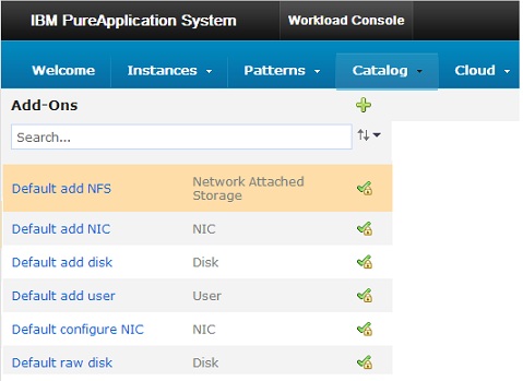
You can add the following types of add-ons to virtual system pattern parts:
| Disk | Adds a virtual disk to the virtual machine and optionally formats the file system and mounts the disk. A raw disk is a virtual disk that is added without partitions or formatting. The largest disk allocation that you can set for a virtual machine is 1.8 TB. |
| NIC | Adds a virtual network interface controller to the virtual machine. NIC add-ons are deployed with environment profiles. |
| User | Defines an additional user on the virtual machine. |
Default add-ons
- Default AIX add NIC
- Add a virtual NIC to the virtual machine, configures an IP address, and activate it.
- Default AIX add SAN disk
- Add a virtual disk from SAN storage to the virtual machine and then format and mount it.
This add-on can be added only to IBM Workload Deployer Standalone AIX images. You can deploy this add-on only to a Power Cloud that has a VMC at version 2.4.2 or later. The disk parameter MINIMUM_VMC_LEVEL is displayed as a locked parameter when you add this add-on to an IBM Workload Deployer Standalone AIX image. The cloud must have at least one SAN storage device. The disk parameter DISK_POOL_TYPE is displayed as a locked parameter when you add this add-on to an IBM Workload Deployer Standalone AIX image. Using this add-on, you cannot add two separate disks that are members of the same volume group, but have different mount points. You can, however, add two separate disks that are members of the same volume group, and have the same mount point. You can create a copy of this add-on and update the associated package file.
When you deploy a virtual system pattern that includes this add-on, if no suitable cloud is found, the following message is displayed:
-
No cloud groups can host parts of this pattern.
- Default AIX add disk
- Add a virtual disk to the virtual machine. Optionally format and mount the disk. You cannot add two separate disks that are members of the same volume group, but have different mount points. You can add two separate disks that are members of the same volume group, and have the same mount point. You can create a copy of this add-on and update the associated package file.
- Default add NIC
- Add a new virtual network interface controller (NIC) to the virtual machine, configure IP address information, and activate it. Use this add-on for virtual image parts that support communication using ssh to run scripts after initial activation of the VM.
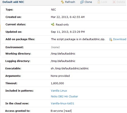
- Default add disk
- Add a virtual disk to the virtual machine. Optionally format and mount the disk.
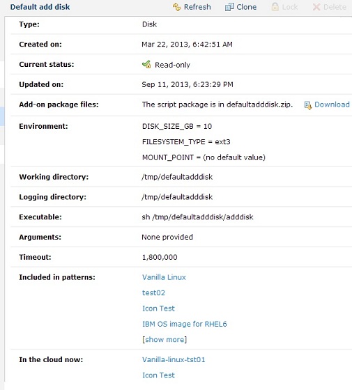
- Default add user
- Define an additional user on the virtual machine. The default add-on script runs a simple add user command. No additional account configuration is performed.

- Default raw disk
- Add a virtual disk to the virtual machine. The disk is added raw, without partitions or formatting. The Delete icon is disabled for this add-on, because deleting this default version from the catalog might affect virtual application deployments.
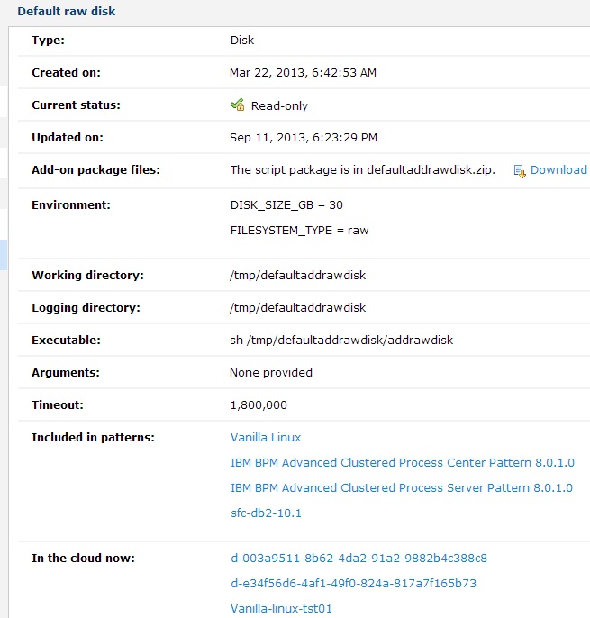
- Default configure NIC
- special add-on that does not have an executable script or any associated environment variables. Used internally in the system.

Create add-ons
Use the workload console to create an add-on and add it to the catalog.
You must have the Create new catalog content permission or the Workload resources administration with full permissions to complete this task. A basic set of add-ons is provided with the product and is available in the catalog. Before creating a new add-on, verify if any default add-ons or other previously created add-ons in the catalog already meet your needs. You might also be able to clone an existing add-on and modify it for your needs before creating a new one.
- Click...
-
Catalog | Add-Ons
- Click the New icon on the toolbar.
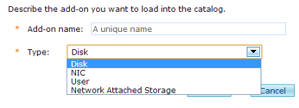
- Enter a unique name for the new add-on. This field is used as the identifier for the new add-on you are adding to the catalog.
- Select the type of add-on.
Disk Adds a virtual disk to the virtual machine and optionally formats the file system and mounts the disk. A raw disk is a virtual disk that is added without partitions or formatting. The largest disk allocation that you can set for a virtual machine is 1.8 TB. NIC Adds a virtual network interface controller to the virtual machine. NIC add-ons are deployed with environment profiles. User Defines an additional user on the virtual machine. - Click OK. The add-on is created and initially populated with default values. The name of the new add-on is displayed in the list of available add-ons, and the default information is displayed in the pane.
- Optional: In the Description field, add a text description to help identify the add-on.
- Optional: In the Add-on package files section, add the package file to the add-on using one of the following methods:
- Use the Browse field to navigate to the location of your customized add-on package file, select the file, and then click Upload
- Download and modify the default add-on implementation.
- Optional: Specify any environment variables in the Environment section.
- Optional: Specify the standard script package parameters for the following fields:
- Work directory
- Log directory
- Executable
- Arguments
- Optional: Set a timeout value (expressed in milliseconds) in the Timeout field. The default value is 60000000. A value of 0 indicates no timeout.
- Optional: Add or change the user permissions for this add-on in the Access granted to field.
You (or other users or groups with appropriate access) can associate the add-on with one or more virtual system patterns.
Clone add-ons
Use the workload console to create an add-on based on an existing add-on. If the default add-ons that are provided with the product or other add-ons already in the catalog do not meet your needs, you can clone an existing add-on and modify it based on your specifications. You must have the Create new catalog content permission or the Workload resources administration with full permissions to complete this task. When you clone an add-on, the cloned copy is initially populated with the configuration data from the original add-on.
- Click...
-
Catalog | Add-Ons
- Select an add-on and click the Clone icon on the toolbar.
- Enter a unique name for the new add-on and click OK. The cloned add-on is created and initially populated with value from the original add-on. The name of the cloned add-on is displayed in the list of available add-ons.
The type of add-on is the same as the original add-on. You cannot change the cloned add-on to a different type.
- Optional: In the Description field, add a text description to help identify the add-on.
- Optional: In the Add-on package files section, add the package file to the add-on using one of the following methods:
- Use the Browse field to navigate to the location of your customized add-on package file, select the file, and then click Upload
- Download and modify the default add-on implementation.
- Optional: Specify any environment variables in the Environment section.
- Optional: Specify the standard
script package parameters for the following fields:
- Work directory
- Log directory
- Executable
- Arguments
- Optional: Set a timeout value (expressed in milliseconds) in the Timeout field. The initial value is the value from the original add-on. A value of 0 indicates no timeout.
- Optional: Add or change the user permissions for this add-on in the Access granted to field.
You (or other users or groups with appropriate access) can associate the cloned add-on with one or more virtual system patterns.
Modify add-ons
You must be assigned the Create new catalog content or the Workload resources administration with full permissions to complete this task. You can modify any add-ons that are not read only and to which you have write access.
- Click...
-
Catalog | Add-Ons
- Select the add-on to be modified. Add-ons that have the locked symbol next to their name in the list are configured as read-only and cannot be modified.
- Modify the detailed information fields as needed.
You can optionally lock the add-on against future modification, and then you (or other users or groups with appropriate access) can associate the add-on with one or more virtual system patterns.
Make add-ons read-only
Use the workload console to configure add-ons as read-only, which prevents users from making any further modifications to the add-on. Making add-ons read-only provides consistent reuse in the cloud. You must have the Create new catalog content or the Workload resources administration with full permissions to complete this task.
- Click...
-
Catalog | Add-Ons
- Select the add-on to configure to read-only status.
- Click Lock in the toolbar.
- Click OK to confirm this setting. When the add-on is locked, it can still be cloned or deleted, but it cannot be modified.
The status of the add-on is changed to Read-only and the Draft icon next to the add-on name is replaced with the Read-only icon.
You (or other users or groups with appropriate access) can associate the add-on with one or more virtual system patterns.
Delete add-ons
Use the workload console to delete an add-on from the catalog and remove any associations with virtual system patterns. To complete this task, you must either have the Create new catalog content permission and be granted all access to the add-on you want to delete, or have the Workload resources administration with full permissions. Add-ons that are in use cannot be deleted. Before you delete an add-on, ensure that it is no longer needed by any virtual system pattern with which it is associated.
- Click...
-
Catalog | Add-Ons
- Verify the add-on can be deleted. An add-on cannot be deleted if it is included in any patterns. If it is included in any patterns, the delete icon is not available and the Included in patterns field displays the linked patterns in which the add-on is included. If the add-on is referenced by any patterns, you can click the pattern name link in the Included in patterns field to go to the Patterns pane for that pattern. From this pane, you can remove the add-on part from the part, or parts, on the pattern.
- Select the add-on and click the Delete icon on the toolbar.
- Click OK.
Fields on the Add-Ons pane
The Add-Ons selection list
The Add-Ons pane displays the list of add-ons currently available in the catalog, including the set of default add-ons provided with the product and any additional add-ons that you or other users have created. The following functions are available for you to work with the list of add-ons:
- Sort by name
- Sort by status
- Sort by created time
- Sort by type
| New icon | Create a new add-on. A dialog is opened where you can specify a name for the add-on and specify the type of add-on (Disk, NIC, or User) being created. |
| Search | Enter the name of an add-on in this field to search for it in the catalog. You can use the up and down arrow keys to sort through the listing of available add-ons. |
| Sort |
|
To work with an add-on, select it by clicking the name in the list. Details about the selected add-on are then displayed in the Add-Ons pane.
Icons in the toolbar

| Refresh | Refresh the status of the add-ons. Update the fields on the Add-Ons pane. |
| Clone | Create a copy of the add-on, even a locked (read-only) add-on, that can be edited. |
| Lock | Configure the add-on as read-only. Lock it to prevent further editing. |
| Delete | Remove the add-on from the catalog. |
Details on the selected add-on
Selecting an add-on displays the name of the add-on in the toolbar at the top of the pane and details about the add-on in the following fields:
| Description | A text description of the add-on. | ||||||||||||||
| Type | Disk, NIC, User. Select type of add-on when the add-on is first created. You cannot edit this selection later. | ||||||||||||||
| Created on | The date and time the add-on was created. Stored internally as the number of seconds since midnight January 1, 1970 UTC. Displayed as the equivalent date and time in the local timezone. | ||||||||||||||
| Current status |
| ||||||||||||||
| Updated on | The date and time the add-on was last updated. Stored internally as the number of seconds since midnight, January 1, 1970 UTC. The value is displayed as the equivalent date and time in the local timezone. | ||||||||||||||
| Add-on package files |
If you are creating a new add-on, you can upload a custom script package. Browse to the location of the package file to be uploaded then click Upload to load the add-on package to the catalog. | ||||||||||||||
| Environment | One or more add-on keys and their default values. Depending on the type of add-on you are displaying, this field manages the environment variables in different ways:
| ||||||||||||||
| Work directory | The directory, on the virtual machine, into which files for this add-on package are to be placed. The default value is /tmp. | ||||||||||||||
| Log directory | The directory, on the virtual machine, that is to contain the log files generated by the add-on. | ||||||||||||||
| Executable | The command to be run for this add-on package. You can specify any command on the virtual machine (for example, wsadmin, tar, ant, or another system command). You can also provide your own script to be run as part of the script package. | ||||||||||||||
| Arguments | One or more parameters that are passed to the executable command. You can optionally specify environment variables and other valid command-line syntax. You can also access the environment by using standard techniques (for example, shell or ant). | ||||||||||||||
| Timeout | The maximum amount of time to wait for the add-on to finish running on a virtual machine. Specify the timeout as the number of milliseconds to wait, or 0 to wait indefinitely for the add-on to complete. The default value is 60000000. | ||||||||||||||
| Included in patterns | Lists the patterns that are currently associated with the add-on. | ||||||||||||||
| In the cloud now | Lists the patterns that are currently associated with the add-on, and that are currently deployed in a cloud environment. | ||||||||||||||
| Access granted to | The access control list for this add-on. Users or groups who have access to this add-on are listed in this field as links. If you have permission, use the Add more entry field to provide access for more users or groups of users. For each user or group of users in this list, you can specify whether they have read, write or all access by clicking the link next to the user or group name. Click remove to remove the user or group from the access list. |
Manage virtual system patterns
Use the console to manage virtual system patterns in IBM PureApplication System W1500.
Review the predefined virtual system patterns provided withPureApplication System, and refer to the IBM PureSystems Centre for additional information about patterns that are available for use with PureApplication System. You can then determine whether an existing virtual system pattern is suitable to your environment, or if you need to create a new pattern, or create a clone of an existing pattern and customize it to meet your needs.
You can manage virtual system patterns in the Virtual System Patterns and Pattern Editor panes in the workload console. Virtual system patterns implement deployment topologies that are created using one or more virtual images and applications in the system catalog.
You can use the virtual system patterns provided by PureApplication System without modification and deploy them to the cloud. You can also create new patterns, or make a copy (clone) of an existing pattern, and use the Pattern Editor to modify the pattern to alter the topology and configuration of your environments.
In a single virtual system pattern, you can include parts from multiple images, as well as script packages and other add-ons in the virtual system pattern, and perform additional configuration tasks on these items as well.
Create virtual system patterns
Create a virtual system pattern when you need to create an environment that is not defined by existing virtual system patterns. Review the predefined virtual system patterns to see if any of the existing virtual system patterns can be used unchanged, or cloned and customized to meet your needs.
- Click Patterns > Virtual Systems.
- Click the New icon on the toolbar.
- Provide the following information about the new virtual system pattern:
- Name
- Enter a unique name for the virtual system pattern.
- Description
- (Optional) Enter a detailed description to identify the virtual system pattern.
- Click OK. When the new virtual system pattern is created, the name of the pattern is added to the list of available patterns, and details of the pattern are displayed in the Virtual System Patterns pane.
You can modify your new virtual system pattern...
- Add, modify, or remove parts.
- Add script packages to the parts or remove script packages from the parts.
- Add add-ons to the parts or remove add-ons from the parts.
- Configure properties for the parts and parameters for script packages as needed.
- Configure advanced options.
- Modify the order in which parts are started.
- Lock the virtual system pattern so it cannot be edited in the future, by making it read-only.
- Deploy the virtual system pattern to the cloud.
- Delete the virtual system pattern if it does not suit your needs.
Clone virtual system patterns
You can clone an existing virtual system pattern and then customize the copy for your environment. Select a virtual system pattern that most closely meets your needs.
Because virtual system patterns are associated with virtual images, you must accept the license agreement for the virtual image associated with the virtual system patterns. If you do not accept the license agreement, you cannot clone the virtual system patterns. To accept the license, click Catalog > Virtual Images and locate the image associated with the virtual system pattern.
You can accept a license and then change the image that the virtual system pattern is using when you define the cloned virtual system pattern. If you change the image but you do not use the image for which you accepted the license, you are not charged for that license.
- Click Patterns > Virtual Systems.
- Select a virtual system pattern.
- Click the Clone icon on the toolbar.
- Provide the following information about the new virtual system pattern:
- Name
- Enter a unique name for the virtual system pattern in the Name field.
- Description
- (Optional) Enter a detailed description to identify the virtual system pattern.
- Virtual image
- From the list, select a virtual image with which to associate the virtual system pattern.
You can edit the new virtual system pattern to associate individual parts with different virtual images.
Use this option if all the parts in the virtual system pattern you are cloning are from a single virtual image. This option switches all of the parts to a different virtual image in the new virtual system pattern.
If the original virtual system pattern contains parts from different virtual images, this option is disabled. In this case, the parts in the new virtual system pattern are associated with the same virtual images as the corresponding parts in the original virtual system pattern.
- Click OK. When the information is processed, the Virtual System Pattern pane displays. The virtual system pattern that you created is added to the list. It is selected so that the information about it is shown on the right.
- Edit the virtual system pattern. To change the virtual system pattern topology,
click the edit icon. You can perform the following actions with virtual system patterns:
- Add or remove parts.
- Edit parts.
- Add or remove script packages to the parts.
- Add or remove add-ons to the parts.
- Configure properties for the parts and parameters for the script packages that have parameters.
- Define advanced options.
- Modify the startup order of the parts.
The Pattern Editor window provides a list of parts.
- Edit the parts on the canvas.
- Configure advanced options.
- Click Done editing.
You can now customize the copy of the virtual system pattern that you created.
You can lock the virtual system pattern against future editing. You can also deploy the virtual system pattern to the cloud.
Delete virtual system patterns
You can delete any virtual system patterns that you own. You must be the owner of the virtual system pattern to delete. You can delete a custom virtual system pattern if the access control lists (ACLs) permit you to do so.
-
Patterns | Virtual Systems virtual system pattern | Delete icon | OK
Modify virtual system patterns
You can modify any virtual system pattern that is not read-only.
If a virtual system pattern can be modified, the edit icon is displayed next to it. If a virtual system pattern is locked and cannot be edited, the locked icon is displayed next to it.
To modify an existing virtual system pattern that is not read-only, you must be the creator of the virtual system pattern or have the correct user permission. The owner for each virtual system pattern is shown on the Patterns window for that virtual system pattern. If you do not have write access to the virtual system pattern to modify, you can request access from that owner.
- Click...
-
Patterns | Virtual Systems | virtual system pattern | Edit
- Modify the parts on the canvas by selecting a part from the list and dropping it onto the canvas. The canvas graphically shows the topology of the virtual system pattern.
- Optional: Configure advanced options.
- Optional: Configure the order in which the parts are to deploy.
- Click the Done editing icon.
You finished modifying this virtual system pattern and it is now ready to be deployed to the cloud.
You can lock the virtual system pattern against future modification. You can deploy the virtual system pattern to the cloud.
Make virtual system patterns read-only
You can deploy both draft and read-only virtual system patterns for testing or production. Making a virtual system pattern read-only prevents further edits to the topology definition and ensures consistent reuse in the cloud. You must have edit access to the virtual system pattern to make read-only. If the pattern is read-only already, you cannot change it. To make a virtual system pattern read-only, ensure that no one with the permission to edit the virtual system pattern intends to change it. You can make virtual system patterns read-only to prevent further editing of the virtual system pattern.
- Click...
-
Patterns | Virtual Systems | virtual system pattern
Virtual system patterns that have the read-only symbol cannot be edited. Virtual system patterns with the edit symbol beside them can be edited.
- To lock editing of the virtual system pattern, click the Lock icon in the toolbar of the Patterns window.
- When prompted, click OK to lock the virtual system pattern.
The virtual system pattern is now read-only.
You can deploy the virtual system pattern to the cloud.
Virtual system pattern views and parts
You can edit a virtual system pattern if it is not read-only and if you have permission to edit it. The topology for a virtual system pattern is graphically shown. Virtual image parts, add-ons, and script packages can be dropped onto an editing canvas to create or change relationships between the parts that define the topology.
The Virtual System Patterns pane
When you select a virtual system pattern to edit, information about the virtual system pattern, such as the topology, is displayed in the Virtual System Patterns pane.
The Pattern Editor pane
Click Edit on the toolbar of the Virtual System Patterns pane to open the Pattern Editor pane for the selected virtual system pattern. Use the Pattern Editor pane to select virtual image parts, add-ons, and script packages from the available lists.
Virtual image parts
Selecting Parts on the Pattern Editor displays a list of the parts that you can drop onto the virtual system pattern canvas. These parts are determined by the virtual images you are using.
Some virtual image parts represent multiple instances. These graphical parts on the editing canvas show the number of instances of the part. You can specify from 1-999 instances.
You can configure the parts either when you deploy the virtual system pattern or directly from the part before deployment. To configure the part before deploying it, click the edit properties icon for the part on the editing canvas.
Script packages
The Scripts option on the Pattern Editor displays a list of the script package parts that you can drop into the virtual image parts. This list can contain script packages associated with the virtual image and additional packages that you have defined for use with the system. Script packages can then be added to the virtual image parts.
Add-ons
The Add-ons option on the Pattern Editor displays a list of the add-on package parts that you can drop into the virtual image parts. Add-ons can then be added to the virtual image parts.
Customized versions of each of these add-on types can also be available if you clone or create new add-ons in the catalog. Add-ons are run before script packages.
Parts on the editing canvas
When you drop the parts onto the canvas in the Pattern window, they interact in specific and predictable ways. Though there are no columns visible and there are no column labels on the canvas, objects fall into general groups. The objects are placed in the following general locations on the canvas:
- Managers on the left
- The left side of the editing canvas contains parts that act as managers of other parts. For example, this column contains dmgrs and job managers. These managers manage the objects (nodes and connections) in the other two sections. You can add a manager, then add the nodes, and the nodes federate to the manager. Alternatively, you can add the nodes first and then add a single manager, and the nodes federate to the manager. You can have both a dmgr and a job manager in one virtual system pattern.
- Nodes in the center
- The center area contains managed nodes, for example custom nodes, administrative agents, or standalone nodes. The nodes are automatically federated into the managers in the left column. Administrative agents are registered with the job manager. Standalone servers can be federated to a dmgr if one is present.
- Connections on the right
- The right area contains connection parts. For example, the right of the editing canvas can contain IBM HTTP Server parts that route the traffic for the nodes. The right area can also contain an On demand routers part if you are editing a virtual system pattern from an IBM WAS Hypervisor Edition Intelligent Management Pack virtual image.
Interaction between virtual image parts
Virtual image parts can be defined to interact with other virtual image parts. When the interacting virtual image parts are included in the same virtual system pattern, the result is cross configuration. For example, when a custom node (or IBM HTTP Server) and a dmgr are placed in the same virtual system pattern, they are automatically cross configured. The result of this operation is that the custom node is federated to the dmgr. Similarly, administrative agents (or dmgrs) are registered with a job manager.
Virtual image parts can be cross configured if the virtual system pattern editor can determine a unique relationship. If it is unable to do so, no cross configuration occurs. For example, if a custom node is added to a virtual system pattern with two dmgrs, no federation takes place. However, if one of the dmgrs is later removed, cross configuration occurs because a unique relationship now exists.
If you have enabled the WAS 7.0.0.17 with Intelligent Management Pack or later image, an on demand router part is available to use in the virtual system patterns. If the on demand router part is used in a custom virtual system pattern, a dmgr part that is enabled with Intelligent Management Pack is also required. Without the dmgr part that is enabled for the Intelligent Management Pack, virtual system patterns with an on demand router part are not valid. However, if there is a dmgr part that is enabled with Intelligent Management Pack, a custom node part that is enabled with Intelligent Management Pack is not required.
You can use the version indicator on the parts to ensure that they are referencing the same version of the virtual image in the catalog. For example, the dmgr part and the on demand router part must reference a virtual image version that is enabled with Intelligent Management Pack. These two parts reference the same version of the virtual image in the catalog. If the version of a part is incorrect, you can change it when the part is on the editing canvas. Hovering over the part name opens a window with additional information about the virtual image.
Associate script packages with virtual system patterns
You can associate a script package with a virtual system pattern. You must create the script package before you can associate it with a virtual system pattern.
- Click...
-
Patterns | Virtual Systems | virtual system pattern
The virtual system pattern must be editable (not read-only).
- Click Edit on the toolbar to modify the virtual system pattern. The Pattern Editor pane is displayed.
- In the list of assets, expand the Scripts section to view the list of available script packages.
- Add a script package. Drag the script package to add onto the appropriate virtual image part on the canvas. The script package is associated with the part.
Certain virtual image parts might have restrictions on your ability to add scripts. For example, DataPower virtual images do not support access to the virtual machine using ssh. Because of this restriction, scripts cannot be added to this type of image. If you attempt to add a script to this type of image, the script is not added, and the following error message is displayed:
-
Neither script package nor add-ons can be added to this kind of image part.
If multiple script packages are included with a virtual system pattern, when the pattern is deployed the scripts are run in the same order in which they were added to that virtual system pattern. If a script runs on multiple IBM WAS virtual machines on the virtual system pattern, then the script runs on the virtual machines in the following order:
- Stand-alone Nodes
- Deployment Manager
- Job Manager (version 7.0.0.x and 8.x patterns only)
- Administrative Agent (version 7.0.0.x and 8.x patterns only)
- Custom Nodes
- IBM HTTP Server
- Optional: Configure properties defined in the script package as needed. Properties added to script packages can be configured when associating the script package with a part, or it can be defined during deployment. To view and configure script package properties, click the Parameters icon on the script package in the Pattern Editor canvas. You can also use a variable syntax to set the value for properties whose value is not yet known.
- Continue working with the virtual system pattern by adding and configuring additional parts, scripts, and add-ons as needed. When finished, click Done editing to close the Pattern Editor.
When the virtual system pattern is completed, you can deploy it to the cloud.
Associate add-ons with virtual system patterns
You can associate an add-on with a virtual system pattern. You must create the add-on or plan to select it from the list of available default add-ons before you can associate it with a virtual system pattern.
You can select add-ons in the catalog and add them to a virtual system topology pattern part when you manage the virtual system patterns. When you deploy the virtual system pattern, you provide the parameters for the add-ons to customize the hardware and operating system configuration.
As you associate add-ons with the virtual image parts, be aware of the following considerations:
- While all of the default add-ons provided with the product are shown in the catalog, not all of these default add-ons can be associated with all parts when you are creating virtual system patterns. Depending on the parts you select for your pattern, only those add-ons that are valid for the selected parts are displayed in the Pattern Editor pane.
- Certain virtual image parts might have restrictions on your ability to add add-ons. For example, DataPower
virtual images do not support access to the virtual machine using ssh. Because of this restriction, add-ons cannot be added to this type of image. If you attempt to add an add-on to this type of image, the add-on is not added, and the following error message is displayed:
-
Neither script package nor add-ons can be added to this kind of image part.
- At deployment time, all add-on operations are run before the custom script packages are run. The order in which add-ons are run at deployment cannot be specified in a virtual system pattern, unlike scripts and parts. Add-ons always run as the system is created. They are not initiated by users, and they do not run at deletion. Depending on the type of add-on, special processing is performed during deployment to add the additional hardware to the virtual machine as needed.
- Click...
-
Patterns | Virtual Systems | virtual system pattern
The virtual system pattern must be editable (not read-only).
- Click Edit on the toolbar to modify the virtual system pattern. The Pattern Editor pane is displayed.
- In the list of assets, expand the Add-ons section to view the list of available add-ons.
- Include an add-on in the virtual system pattern. Drag the selected add-on onto the appropriate virtual image part on the canvas. The add-on is associated with the part.
Certain virtual image parts might have restrictions on your ability to include add-ons. For example, DataPower virtual images do not support access to the virtual machine using ssh. Because of this restriction, most add-ons cannot be added to this type of image. If you attempt to include an add-on to this type of image, the add-on is not included, and the following error message is displayed:
-
Neither script package nor add-ons can be added to this kind of image part.
If multiple add-ons are included with a virtual system pattern, when the pattern is deployed the add-ons are run in the same order in which they were added to that virtual system pattern. If an add-on runs on multiple IBM WAS virtual machines on the virtual system pattern, then the add-on runs on the virtual machine in the following order:
- Stand-alone Nodes
- Deployment Manager
- Job Manager (version 7.0.0.x and 8.x patterns only)
- Administrative Agent (version 7.0.0.x and 8.x patterns only)
- Custom Nodes
- IBM HTTP Server
Add-ons are run before script packages.
- Optional: Configure properties defined in the add-on as needed. Properties can be configured when associating the add-on with a part, or it can be defined during deployment. To view and configure add-on properties, click the Parameters icon on the add-on in the Pattern Editor canvas. You can also use a variable syntax to set the value for properties whose value is not yet known.
- Continue working with the virtual system pattern by adding and configuring additional parts, scripts, and add-ons as needed. When finished, click Done editing to close the Pattern Editor.
When the virtual system pattern is completed, you can deploy it to the cloud.
Deploy virtual system patterns
You can deploy virtual system patterns to run in a cloud groups. Configure the virtual system pattern, including the advanced configuration, and ensure that it is ready to be deployed. You can deploy either draft or committed virtual system patterns for testing or production. The time that it takes to deploy a virtual system depends on several factors, such as the size of the virtual system pattern parts and the interdependencies of parts in the pattern definition, network usage, storage usage, and the provisioning speed of the virtual machine on the cloud infrastructure.
Connectivity issues with the DNS server can cause increased deployment times or failed deployments. The network administrator for the target network must check the routing tables of the DNS server to ensure that it can resolve the network address of the system.
- Click
-
Patterns | Virtual Systems | virtual system pattern
- Click the Deploy icon on the toolbar.
- Provide the necessary information to deploy the virtual system pattern. The parameters required differ depending on the defined configuration and any associated script packages.
- Virtual system instance name
- Enter the name of the virtual system instance in which to deploy this virtual system pattern.
- Choose Environment
- You can either deploy the virtual system pattern to a specific cloud group or you can deploy the virtual system pattern by using an environment profile. You can then specify a cloud group or groups for deployment. Make your selections from the following options:
- IP version
- Click one of the IP version options (IPv4 or IPv6).
- Choose profile
- Select this option to deploy the virtual system pattern by
using an environment profile. Then select the environment Type and a valid environment Profile from the lists. You can also set a Priority (High,
Medium, or Low).
If the Pattern deployer option was chosen, you cannot specify an IP address that is contained within the IP groups which are defined in the system.
- Schedule deployment
- Click this link to provide information about when the virtual system pattern is to be deployed and for how long. You can deploy the virtual system pattern immediately
after providing the information in the dialog or you can schedule
deployment by using the following options:
- Start now
- Deploys the virtual system pattern immediately after providing the required information in the dialog. Start now is the default option.
- Start later
- Provide the date and time to deploy this virtual system pattern at a later time.
- Run indefinitely
- Runs this virtual system pattern continuously. Run indefinitely is the default option.
- Run until
- Use this option to provide the end date and time for the virtual system pattern to stop running.
- Configure virtual parts
- For each virtual image part that requires information, click the link and provide the information for each configuration parameter shown. The set of parameters depends on the type of part. The parts that require information are different depending on the type of virtual image to be deployed and the type of hypervisors in the cloud. For example, parts for a WAS image would require different information than parts for a DB2 image.
Do not use the root user as the WebSphere administrative user name.
When specifying values for DB2 parameters, be aware that owner and user group names, as well as instance owner names, fenced user names, and DB2 administration server (DAS) user names can only have up to 8 characters.
If the information for each of the virtual image parts is complete, a green check mark is shown next to the virtual image part. If some information is missing, the check box does not contain a green check mark. If so, you must provide the required information.
If you are using an environment profile there might be additional fields to configure for the parts. If the environment profile specifies that the virtual system pattern deployer is to provide the IP address, the IP addresses must also be provided for the parts.
Specify the following part information:
- In cloud group
- Select the cloud group. If an alias was provided to define the cloud group in the environment profile, then the alias name is available to be selected in this field.
- IP Group
- Select an IP group. If an alias was provided to define the IP group in the environment profile, then the alias name is available to be selected in this field.
- Addresses
- Provide both the host name and the IP address. The host name and IP address must not exist in the selected IP group.
If you are deploying parts with add-ons, you can configure fields for those add-ons if they were not configured when the part was created and locked to editing during deployment.
- Deploy the virtual system pattern. When all of the information is provided correctly in the dialog, click OK to deploy the virtual system pattern.
The virtual system pattern is deployed to the cloud and runs in the selected virtual system instance.
On a topology deployment, some parts can reserve CPU, or memory, or both. These fields affect how the CPU and memory are configured on the underlying hypervisor.
The CPU and memory limits are set and reserved. This setting prevents the CPU from being overcommitted but reduces license usage.
To add nodes to the virtual system pattern, stop the virtual system in which the cloud is running.
9.1. Configure parts
Before deploying a virtual system pattern to run in a cloud group, you must configure the parts included in the virtual system pattern. You can configure the parts included in the virtual system pattern in two ways:
- You can configure the part when you deploy the virtual system pattern.
- You can configure the part properties from the editing canvas of the Pattern Editor window.
To configure parts for a virtual system pattern, the virtual system pattern must either be open, or in the process of being edited or deployed. When editing part properties from the virtual system pattern, you can lock the values so that they cannot be changed during deployment. The parts that require information are different depending on the type of virtual image to be deployed, and the types of hypervisors in the cloud. For example, parts for a WAS image require different configuration than parts for a DB2 image.
- Open the Properties pane for the part by using one of the following methods:
- Edit the virtual system pattern:
- Click
-
Patterns | Virtual Systems | virtual system pattern
- From the toolbar, click Edit.
- For each virtual image part on the canvas that requires configuration, click the Properties icon.
You can also configure any script packages or disk or user add-ons on the parts. NIC add-ons require an environment profile for configuration.
- Click
- Deploy the virtual system pattern:
- Click Patterns > Virtual Systems.
- From the Virtual System Patterns pane, click the Deploy icon on the toolbar.
- When deploying a virtual system pattern, you must describe the virtual system instance to deploy. To configure parts, click Configure virtual parts.
When the information for each of the virtual image parts in the virtual system pattern is provided, a green check mark is displayed next to the virtual image part. If information for one of these parts is missing, then the check box for the Configure virtual parts field does not contain a green check mark. In this case, click Configure virtual parts, and then click the link for the virtual image part that is missing information.
- Edit the virtual system pattern:
- Provide the necessary information. Part properties
vary, depending on the type of part you are editing, and the scripts and add-ons it includes. If the script packages have parameters, you can also edit these properties.
links.
You can edit the following properties for add-ons while editing the part or during the deployment process:
- Disk add-on
- Edit one of the following properties:
- DISK_SIZE_GB
- FILESYSTEM_TYPE
- MOUNT_POINT
- Raw disk add-on
- Edit one of the following properties:
- DISK_SIZE_GB
- FILESYSTEM_TYPE
The FILESYSTEM_TYPE property is read-only.
- User add-on
- Edit one of the following properties:
- USERNAME
- PASSWORD
- Verify password
NIC add-ons require an environment profile for configuration.
- Optional: Lock the properties. If you are editing part properties from the virtual system pattern, you can lock the values so that they cannot be changed during deployment. Use the unlocked or locked icon next to each field on the Properties window to change the status of the field. By default, the parts properties are not locked so you must lock them to prevent them from being changed during deployment.
The virtual image parts for the virtual system pattern are configured.
Deploy the virtual system pattern to the cloud.
9.2. Change the deployment order of parts
When you create a virtual system pattern, the parts, scripts, and add-ons run in a specific order at deployment. For example, add-ons always run before scripts. Use the workload console to set the deployment order of parts in a virtual system pattern. To modify the order of the parts deployed for an existing virtual system pattern that is not read-only, you must be the creator of the virtual system pattern or have the correct user access. The owner for each virtual system pattern is shown on the Patterns window for that virtual system pattern. If you do not have write access to the virtual system pattern you want to edit, you can request access from that owner.
The order of default parts cannot be edited when they are disabled. The ordering on these parts is the default order provided by a virtual system pattern template.
You can change the order of any scripts that run when the virtual machine is created.
You cannot change the order of the following items:
- Scripts that are run by a user
- Deletion script packages
- Click
-
Patterns | Virtual Systems | virtual system pattern | Edit | Ordering
- Order the parts to deploy by group. Groups of parts are numbered and labelled with the clock icon. Dragging the parts adds constraints. Parts can be moved between groups or to create new groups. Parts within a group do not necessarily deploy in the order in which they are shown within the group. The groups do deploy relative to the other groups above and below them. The text to the left of the part and script listing describes the order of deployment for each part.
- Click Topology to return to the initial view of the virtual system pattern.
- Click Done editing.
The virtual system pattern is ready to be deployed to the cloud.
Configure the advanced options or deploy the virtual system pattern to the cloud.
9.3. Processing virtual system patterns
When deploying a virtual system instance that is a collection of virtual machines, IBM PureApplication System W1500 virtual system pattern processing follows a specific startup sequence.
A virtual system pattern is one or more virtual images and applications from the PureApplication system catalog that implements a deployment topology.
When deploying a virtual system instance as a collection of virtual machines, it is helpful to understand the startup sequence that occurs during PureApplication System virtual system pattern processing. The processing occurs in the following sequence:
- Virtual machines (defined by the virtual image parts)
are started concurrently, where possible. Virtual image parts might have a dependency on other parts when cross configuration takes place as part of the virtual machine startup. In such cases,
the dependent virtual machines are started second.
For example, in a WAS virtual system pattern, the following sequence typically occurs:
- A dmgr is started before any custom nodes. The custom nodes can be started either sequentially or concurrently with each other, depending on the image.
- When the virtual machines are activated, custom nodes are federated in the topology. In addition, administrative agents and dmgrs are registered with a job manager if one is present in the topology.
- For each of the virtual machines, any defined add-ons are run.
- The advanced setting scripts that are provided by IBM to define the system configuration are run. For example, in a WAS virtual system pattern, this set of supplied scripts define settings such as HTTP session clustering properties, and security.
- For each of the virtual machines, script packages are run. If a virtual system pattern specifies multiple script packages for the same virtual machine, the script packages are run in the order they were added to the virtual system pattern.
For example, if you are deploying a WAS virtual system pattern with a dmgr and two custom nodes, the following processing occurs:
- The dmgr virtual machine and the dmgr profile are started.
- The first custom node virtual machine is started and the custom node profile is federated.
- The second custom node virtual machine is started and the custom node profile is federated.
Pattern deployment status is available from the user interface under Instances -> Virtual Systems.
Script execution and results
Script packages that are defined to run at deployment time and fail during a virtual system deployment will normally cause the virtual system to be placed in a failed state. There are a few scripts, however, that will not result in a failed deployment if they fail during deployment:
- Must Gather Logs
- Default Add User
- Default Add Nic
- Default AIX add NIC
- WAS Hypervisor scripts
Each script execution has an associated script status. After the script has completed execution, the script status will have one of the following values:
- RM01012 - COMPLETE
- Completed successfully with a return code of 0.
- RM01013 - FAILED
- Completed with a return code other than 0 or 2, or did not get any result back from the virtual machine,
- RM01014 - FAILED
- Script could not be transferred to the virtual machine.
- RM01015 - FAILED
- Script did not complete before the time out expired.
- RM01059 - WARNING
- Completed with a return code of 2.
10. Export virtual system patterns
Virtual system patterns are topology definitions for repeatable deployment that can be shared. You can export a command line script that reconstructs a virtual system pattern on a different system than the one on which it was created.
Use the artifacts that are generated by the exportPattern.py script, you can export virtual system patterns from one system and import them to another system. This command-line interface (CLI) script reconstructs the original virtual system pattern on another system by using the importPatterns.py script. The reconstructed virtual system pattern contains the same properties as the original script:
- Parts
- Property values and metadata
- Scripts
- Script environment variables
- Advanced options
- Add-ons
- Add-on parameter values
- Ordering
- Status (read-only)
Note that the script environment variables include the set of key/value pairs that are defined to the run time environment of the script, as specified in the Environment section of the Script Packages pane.
All script package configuration parameters, including executable commands and arguments (as specified in the Executable and Arguments sections, respectively, of the Script Packages pane), are included in the export and subsequent import of the virtual system pattern when using the command line interface. If script parameters are also included in a cbscript.json object file as part of the script package, the values exported from the user interface do not overwrite the values in the cbscript.json file.
Export a virtual system pattern
Use the samples/exportPattern.py script to export the virtual system pattern. Use the standard CLI parameters to specify the host name, user ID, and password to access the virtual system pattern, and the location of the exportPattern.py script. In addition, use the -a parameter, which you can also format as --acceptcert, so that SSL certificates from the system are automatically accepted. Specify both the file name and virtual system pattern, as shown in the following example:
pure -h <hostname.com> \
     -u <user> \
     -p <password> \
     --acceptcert \
     -f ../samples/exportPattern.py
     -p <pattern_name>
     -t <target_directory>
Options
Use the following options with the exportPattern.py script:
- -p <pattern_name> or --pattern <pattern_name>
- Name of the virtual system pattern to be exported. The name you specify must uniquely identify a virtual system pattern. If you do not specify the virtual system pattern, a list of virtual system patterns that are defined is displayed and you are prompted to select one.
- -t <target_directory> or --target <target_directory>
- Indicates that the exported artifacts will be written to the specified target folder or file name for the .tgz/.tar.gz file.
- --passwords
- Includes BASE64 encoded passwords in the pattern definition file. By default, password properties are not exported.
By default, only the archive files of script packages of the pattern are exported. To export the associated virtual images, script packages, and add-ons, you can specify the following options:
- --downloadAll
- Indicates that all associated artifacts are exported with the pattern, including the virtual images, script packages, and add-ons.
- -d|--download <filter_file>
- Indicates that only the artifacts that are listed in the filter file are downloaded. The filter is one JSON file formatted similar
to the following example:
{
    "add_ons":[
        {"name":"ADD_ON_NAME"},
        ...
    ],
    "script_packages":[
        {"name":"SCRIPT_PACKAGE_NAME"},
        ...
    ],
    "virtual_images":[
        {"name":"IMAGE_NAME","version":"IMAGE_VERSION","build":"REFID"},
        ...
    ]
}
The file directory structure for the exported virtual system pattern is similar to the following example:
    /
        patterns.json    //The JSON serialization format for the exported pattern         /images
            test_image.ova
        /script_packages
            test_script1.zip
            test_script1.zip
        /add_ons
            test_add_on.zip
The JSON serialization format for the virtual system pattern is similar to the following example:
[
   {
      "references":{
         "virtual_images":[
            {"name":"IMAGE_NAME","version":"IMAGE_VERSION","build":"REFID"},
            {"name":"IMAGE_NAME","version":"IMAGE_VERSION","build":"REFID","file":"OVA_FILE_FOR_IMPORT"},
                //"file" is the relative path for the OVA file when exporting the virtual image             ...
         ],
         "add_ons":[
            {"name":"ADD_ON_NAME","type":"ADD_ON_TYPE"},       //"type" is optional.
            {"name":"ADD_ON_NAME","type":"ADD_ON_TYPE","file":"ADD_ON_FILE"},
                //"file" is the relative file path when exporting the add-on.
            ...
         ],
         "script_packages":[
            {"name":"SCRIPT_PACKAGE_NAME"},
            {"name":"SCRIPT_PACKAGE_NAME","file":"SCRIPT_PACKAGE_FILE"},
               //"file" is the relative file path when exporting the script package.
            ...
         ],
   },
      "name":"PATTERN_NAME",
      "description":"PATTERN_DESCRIPTION",      //The existing description, if applicable.
      "parts":[
         {
            "virtual_image_ref":"IMAGE_INDEX,
                  //The index for the images in the reference section, beginning with 0.
            "part":PART_NAME",
            "count": COUNT,                     //The count for the image part. The default is 1.
            "properties":[
               {
                  "class":"PROPERTY_CLASS",
                  "key":"PROPERTY_KEY",
                  "value":"PROPERTY_VALUE",
                  "locked":true | false         //Optional. The default is false.
               },
               ...
            ],
            "script_packages":[
               {
                  "script_package_ref":"SCRIPT_PACKAGE_INDEX",
                        //The index for the script packages in the reference section.
                  "parameters":[
                     {
                        "key":"PARAM_KEY",
                        "value":"PARAM_VALUE",
                        "locked":true | false   //Optional. The default is false.
                     },
                     ...
                  ]
                  starts_after:[ {"part_ref":PART_INDEX_1,"script_ref":PART_SCRIPT_INDEX_1}, ...]
                        //Optional. Specifies the order in which the script parts are started.
               }
            ],
            "add-ons":[
               {
                  "add_on_ref":ADD_ON_INDEX,
                        //The index for the script packages in the reference section.
                  "parameters":[
                     {
                        "key":"PARAM_KEY",
                        "value":"PARAM_VALUE",
                        "locked":true | false   //Optional. The default is false.
                     }
                     ...
                  ],
               }
            ],
            "configurations":[         //Optional. For script packages that are shipped with the virtual image.
               {,
                  "name":"CONFIGURATION_NAME",
                  "parameters":[
                     {
                        "key":"PARAM_KEY",
                        "value":"PARAM_VALUE",
                        "locked":true | false   //Optional. The default is false.
                     },
                     ...
                  ],
               }
            ],
            starts_after:[PART_INDEX_1,PART_INDEX_2, ... ]
                 //Optional. Specifies the order in which the parts are started.
         }
      ],
      "advanced_options":[
         ...
      ]
      "read_only":true | false     //Optional. The default is false.
   },
   ...
}
Helpful tips
Export the virtual images can take an extended amount of time depending on the size of the images. You can reduce the download time and the amount of space required by not downloading virtual images that are already included in the target environment, for example WAS Hypervisor Edition virtual images.
You can export the virtual system pattern without first specifying the -d or --downloadAll options. You can then extract the reference part from the exported pattern definition to create your filter file.
References to images in the JSON file refer to exact image numbers. You might need to update these references when importing to another system if it has different versions of those images.
Import virtual system patterns
Virtual system patterns are topology definitions for repeatable deployment that can be shared. You can export a command line script that reconstructs a virtual system pattern on a different system than the one on which it was created.
Use the artifacts that are generated by the exportPattern.py script, you can export virtual system patterns from one system and import them to another system. This command-line interface (CLI) script reconstructs the original virtual system pattern on another system by using the importPatterns.py script. The reconstructed virtual system pattern contains the same properties as the original script:
- Parts
- Property values and metadata
- Scripts
- Script parameter values
- Advanced options
- Add-ons
- Add-on parameter values
- Ordering
- Status (read-only)
Import a virtual system pattern
Use the samples/importPatterns.py script to import the virtual system pattern. Use the standard CLI parameters to specify the host name, user ID, and password to access the virtual system pattern, and the location of the importPatterns.py script. In addition, use the -a parameter, which you can also format as --acceptcert, so that SSL certificates from the system are automatically accepted. Specify both the file name and virtual system pattern, as shown in the following example:
pure -h <hostname.com> \
     -u <user> \
     -p <password> \
     --acceptcert \
     -f ../samples/importPatterns.py \
     -s <target_source_directory>
Options
Use the following options with the importPatterns.py script:
- -s <target_source_directory> or --source <target_source_directory>
- Indicates that the patterns and the associated artifacts are uploaded from the specified source folder or file name for the .tgz/.tar.gz file.
Update the referenced virtual image
The script uses the values specified in the references definition of the JSON file to match the virtual image in the target environment.
"references": {
"virtual_images": [
{"name": "IMAGE NAME", "version": "IMAGE_VERSION", "build": "REFID"},  .
] ,
In some cases, you might need to update the references
definition for an exported pattern to match the target environment in which the pattern is imported.
CAUTION:
Ensure that the updated virtual image accepts the same set of configuration properties. Otherwise, an exception will occur during the import process.
In the following example, the virtual image of the exported pattern is at the WAS Hypervisor Edition v8.0.0.1 level.
- The original references definition:
"virtual_images": [
{"name": "IBM WAS Hypervisor Edition 8.0.0.1", "version": "8.0.0.1", "build": "34964.449"},  .
] ,
To match the target environment, the virtual image of the imported pattern is then updated to the v8.0.0.2 level.
- The updated references definition:
"virtual_images": [
{"name": "WAS 8.0.0.2", "version": "8.0.0.2", "build": "112022.490"},  .
] ,
Providing native language support
To provide native language support for the virtual system pattern name and description, you can add the messages.properties file of each locale in the locales directory. In the following example, the locales directory contains message files in English, French, and Simplified Chinese. The format of the messages.properties file follows Java internationalization specifications.
    /
        patterns.json
        .
        /locales
            messages.properties
            messages_en.properties
            messages_fr.properties
            messages_zh_CN.properties
Use a web server to host the virtual images referenced by the virtual system pattern
Because the size of the virtual image can be larger than several gigabytes, you can host the virtual image on a web server to import it in several different environments. Update the virtual image values in the references definition as shown in the following example:
"references": {
    "virtual_images": [
        {"name": "IMAGE NAME", "version": "IMAGE_VERSION",""build": "REFID", "url", "OVA_URL_FOR_IMPORT", "user": "USER", "password": "PASSWORD"}, .
    ] ,
The "url" value is the HTTP or HTTPS URL for the virtual images. The optional "user" and "password" values are used for basic authorization.
Virtual System Patterns pane reference
The Virtual System Patterns pane lists the virtual system patterns that are available in the catalog, and provides fields that you can view and modify to configure the topology. The Virtual System Patterns pane includes detailed information about the selected pattern and graphically shows the parts, scripts, and add-ons in the topology.
The Virtual System Patterns pane includes the following information:
- A list of the virtual system patterns available in the catalog. You can scroll through this list, search for a particular pattern, and sort the patterns by name, status, or by creation time.
- When you select a pattern from the list, detailed information about the pattern is displayed, including a view of the topology.
- A toolbar provides additional capabilities to manage your patterns. You can add new patterns to the catalog, delete patterns, modify the details about a selected pattern, lock a pattern to prevent further modification, clone and modify an existing pattern to create a new pattern, and deploy patterns.
The virtual system patterns list
The Virtual System Patterns pane provides a list of virtual system patterns that are available in the catalog. You can scroll through the list, search for a particular pattern, sort the list in several ways, or select a pattern in the list to view its details or manage its configuration.
Beside each pattern name in the list is one of two icons:
| Draft | You can modify the configuration for this pattern. |
| Read-only | The pattern is locked against future modification. You can, however, create a copy of the pattern that you can then modify and save to the catalog as a new pattern. |
Use the Search field at the top of the list to search for a particular pattern. For example, if you search on the phrase, cluster, the list is filtered to display only those patterns with the word cluster in the title. Clear the Search field to display the full list of available patterns.
Use the Sort icon to reorder the list of patterns in one of the following ways:
| Sort by name | Sort the patterns alphabetically by name. |
| Sort by status | Sort the patterns by Draft or Read-only status. |
| Sort by created time | Sort the patterns in order of the date and time value in the Created on field. |
Virtual system pattern details and topology
Select a virtual system pattern from the list of available patterns to display the basic properties for the pattern. The name of the selected virtual system pattern is displayed in a reserved area of the toolbar.
The following fields provide additional details about the selected virtual system pattern:
| Description | A text description of the virtual system pattern. This description can help identify the virtual system pattern to other users who have access to it. If the current status of the pattern is Draft, you can modify this description as needed. | ||||
| Created on | The date and time when the virtual system pattern was created. Stored internally as the number of seconds since midnight January 1, 1970 UTC. Displayed as the equivalent date and time in the local time zone. | ||||
| Current status | The status of the virtual system pattern, which can be one of the following values:
| ||||
| Updated on | The date and time when the pattern was last updated. Stored internally as the number of seconds since midnight January 1, 1970 UTC. Displayed as the equivalent date and time in the local time zone. | ||||
| In the cloud now | Lists the virtual system instances that were created from this virtual system pattern, and that are currently deployed in a cloud environment. If there are no running virtual system instances, the value displayed in this field is (none). | ||||
| Access granted to | The access control list for this virtual system pattern. Initially this field is set to the role of the owner of the virtual system pattern. Users or groups who have access to this pattern as listed in this field as links. If you have permission, use the Add more entry field to provide access for more users or groups of users. For each user or group of users in this list, you can specify whether they haveread, write, or all access by clicking the link next to the user or group name. Click remove to remove the user or group from the access list. | ||||
| Topology for this pattern | Displays any warnings or errors. This section identifies the types of hypervisors to which the virtual system pattern deploys, and provides a graphical representation of the topology.
| ||||
| Comments | Display any comments that have been added to the virtual system pattern. You can expand this section to display a free form space to add comments, and then click Add Comment to add the comment to the pattern. |
Functions in the toolbar
You can perform any of the following tasks by selecting an icon in the toolbar:
| New | Create a new virtual system pattern. |
| Refresh | Refresh the virtual system pattern display after any changes, such as modifying the configuration or deploying the pattern. |
| Deploy | Deploys the virtual system pattern . This icon is available when the virtual system pattern contains at least one virtual part. |
| Edit | Opens the virtual system pattern for editing. This option is available only if the current status of the virtual system pattern is Draft. |
| Clone | Makes a copy of the selected virtual system pattern. Use this option to create a new virtual system pattern that has the same configuration as the original pattern, and then modify the configuration as needed to create a new pattern. This function is also useful if the status of the original virtual system pattern is Read-only and cannot be edited. |
| Lock | Sets the status of the virtual system pattern to Read-only, preventing the pattern from further modification. |
| Delete | Deletes the virtual system pattern from PureApplication System. |
Pattern Editor pane reference
The Pattern Editor pane contains lists of parts, scripts, and add-ons to graphically work with the topology. You can use these parts, scripts, and add-ons to customize a virtual system pattern topology that you can then deploy into your cloud environment.
Parts, scripts, and add-ons
From the toolbar in the Virtual System Patterns pane, after creating or selecting a virtual system pattern, click edit to open the Pattern Editor. The Pattern Editor provides lists of available virtual image parts, scripts, and add-ons that you can select and drag onto the editing canvas to customize your selected virtual system pattern.
- Parts
- The Parts list displays the virtual image parts available to use in the virtual system pattern.
The parts that are available depend on the virtual images installed and the hardware type of any parts already in the virtual system pattern.
Only parts with the same hardware type as any parts already in the virtual system pattern are available. This list might include any number of the following common virtual image parts:
- Administrative agents
- Advanced Middleware Configuration
- Core OS
- Custom nodes
- DB2 servers
- Deployment managers
- HTTP servers
- Job managers
- On demand routers
- Standalone servers
Hover the cursor over a part label to display additional information about the part and its virtual image. The following actions can be performed:
- Drop parts onto the pane from the Parts list.
- Edit the properties for the parts on the pane by using the edit properties icon on the part.
- Drop scripts or add-ons onto the parts from the Scripts and Add-Ons lists.
- Edit parameters, if the script has parameters by using the edit properties icon on the part.
- Change the count for some types of parts.
- Lock the count.
- Delete a part.
- Change a part so that it comes from a different virtual image.
- Delete scripts or add-ons.
Some virtual image parts represent multiple instances. When you drag the part onto the canvas, you can configure a numerical indicator on the part, so that when the pattern is deployed, multiple instances of the part are generated.
You can configure the properties for the part either when you deploy the virtual system pattern or in the Pattern Editor. In the Pattern Editor canvas, click the Properties icon on the part to be configured and configure the properties as needed. Some properties can be locked from further modification by clicking the lock icon next to the property field.
- Scripts
- The Scripts list displays the script packages that you can drag onto the virtual image parts in the canvas. This list can contain any script packages that are associated with the virtual image and any that you provided for use with PureApplication System. You can add script packages to the parts on the editing canvas. Add scripts by dragging them onto the canvas and dropping them onto the part objects.
- Add-Ons
- The Add-Ons list displays the add-ons that you can add to the parts on the canvas. You can add add-ons to the parts in the canvas by dragging them onto the canvas and dropping them onto the part objects. the following default add-ons are provided with the product:
Default add disk Add a virtual disk to the virtual machine. Optionally format and mount the disk. Default add NIC Add one or more network interface controllers to a node for deployment on a virtual machine. Default add user Add an additional user on the virtual machine. Default raw disk Add a virtual disk to the virtual machine. Does not format or mount the disk. You can also create and customize additional add-ons to meet your needs and add them to the catalog.
Available views on the canvas
When a virtual system pattern is being edited in the Pattern Editor, the graphical topology view is displayed in an editing canvas. You can click either of the following links to view the parts of the virtual system pattern in the canvas:
- Ordering
- This link displays the view showing the order in which the parts are started when the virtual system pattern is deployed. If you are working with a copy of a provided virtual system pattern, there is a recommended order, and this order is the default setting. In this view, the parts are shown in the canvas and numbered in the order they are started. A text description is also displayed describing the order in which the parts are started, with any order constraints for parts and scripts that might have dependencies.
- Topology
- This link is available when you are in the Ordering view. Click it to switch back to the default topology view in which the relationship of the parts is shown.
Functions in the toolbar
From either the Topology or Ordering view, you can select from the following icons and links:
- Refresh
- Forces a refresh of the virtual system pattern to ensure that the diagram shows the current state of the virtual system pattern on the system. Refresh the virtual system pattern if, for example, the virtual system pattern was edited by another user since it was last retrieved by the web browser.
- Undo
- Undo the previous action. The virtual system pattern is saved during the editing process, so use this option to revert to the state of the virtual system pattern before the previous action.
- Undo all
- Undo all changes made in the current editing session for this virtual system pattern. The virtual system pattern is saved during the editing process, so use this option to revert to the state of the virtual system pattern before any modifications were made during the current editing session.
- Done editing
- Indicates that you are done editing and returns to the initial view of the virtual system pattern.
- Advanced options
- This link opens a configuration pane for the virtual system pattern you are editing. The configuration pane contains options that are available for this virtual system pattern.
Manage virtual system patterns
Use the console to manage virtual system patterns in IBM PureApplication System W1500.
Review the predefined virtual system patterns provided withPureApplication System, and refer to the IBM PureSystems Centre for additional information about patterns that are available for use with PureApplication System. You can then determine whether an existing virtual system pattern is suitable to your environment, or if you need to create a new pattern, or create a clone of an existing pattern and customize it to meet your needs. You can manage virtual system patterns in the Virtual System Patterns and Pattern Editor panes in the workload console. Virtual system patterns implement deployment topologies that are created using one or more virtual images and applications in the system catalog.
You can use the virtual system patterns provided by PureApplication System without modification and deploy them to the cloud. You can also create new patterns, or make a copy (clone) of an existing pattern, and use the Pattern Editor to modify the pattern to alter the topology and configuration of your environments.
In a single virtual system pattern, you can include parts from multiple images, as well as script packages and other add-ons in the virtual system pattern, and perform additional configuration tasks on these items as well.
Create virtual system patterns
Create a virtual system pattern when you need to create an environment that is not defined by existing virtual system patterns. Review the predefined virtual system patterns to see if any of the existing virtual system patterns can be used unchanged, or cloned and customized to meet your needs.
- Click...
-
Patterns | Virtual Systems | New icon
- Provide the following information about the new virtual system pattern:
- Name
- Enter a unique name for the virtual system pattern.
- Description
- (Optional) Enter a detailed description to identify the virtual system pattern.
- Click OK. When the new virtual system pattern is created, the name of the pattern is added to the list of available patterns, and details of the pattern are displayed in the Virtual System Patterns pane.
You can modify your new virtual system pattern...
- Add, modify, or remove parts.
- Add script packages to the parts or remove script packages from the parts.
- Add add-ons to the parts or remove add-ons from the parts.
- Configure properties for the parts and parameters for script packages as needed.
- Configure advanced options.
- Modify the order in which parts are started.
- Lock the virtual system pattern so it cannot be edited in the future, by making it read-only.
- Deploy the virtual system pattern to the cloud.
- Delete the virtual system pattern if it does not suit your needs.
Clone virtual system patterns
You can clone an existing virtual system pattern and then customize the copy for your environment.
Because virtual system patterns are associated with virtual images, you must accept the license agreement for the virtual image associated with the virtual system patterns. If you do not accept the license agreement, you cannot clone the virtual system patterns. To accept the license, click Catalog > Virtual Images and locate the image associated with the virtual system pattern.
You can accept a license and then change the image that the virtual system pattern is using when you define the cloned virtual system pattern. If you change the image but you do not use the image for which you accepted the license, you are not charged for that license.
- Click...
-
Patterns | Virtual Systems | virtual system pattern | Clone icon
- Provide the following information about the new virtual system pattern:
- Name
- Enter a unique name for the virtual system pattern in the Name field.
- Description
- (Optional) Enter a detailed description to identify the virtual system pattern.
- Virtual image
- From the list, select a virtual image with which to associate the virtual system pattern.
You can edit the new virtual system pattern to associate individual parts with different virtual images.
Use this option if all the parts in the virtual system pattern you are cloning are from a single virtual image. This option switches all of the parts to a different virtual image in the new virtual system pattern.
If the original virtual system pattern contains parts from different virtual images, this option is disabled. In this case, the parts in the new virtual system pattern are associated with the same virtual images as the corresponding parts in the original virtual system pattern.
- Click OK. When the information is processed, the Virtual System Pattern pane displays. The virtual system pattern that you created is added to the list. It is selected so that the information about it is shown on the right.
- Edit the virtual system pattern. To change the virtual system pattern topology,
click the edit icon. You can perform the following actions with virtual system patterns:
- Add or remove parts.
- Edit parts.
- Add or remove script packages to the parts.
- Add or remove add-ons to the parts.
- Configure properties for the parts and parameters for the script packages that have parameters.
- Define advanced options.
- Modify the startup order of the parts.
The Pattern Editor window provides a list of parts.
- Edit the parts on the canvas.
- Configure advanced options.
- Click Done editing.
You can now customize the copy of the virtual system pattern that you created.
You can lock the virtual system pattern against future editing. You can also deploy the virtual system pattern to the cloud.
Delete virtual system patterns
You can delete any virtual system patterns that you own. You must be the owner of the virtual system pattern to delete. You can delete a custom virtual system pattern if the access control lists (ACLs) permit you to do so.
-
Patterns | Virtual Systems | virtual system pattern | Delete icon
Modify virtual system patterns
You can modify any virtual system pattern that is not read-only.
If a virtual system pattern can be modified, the edit icon is displayed next to it. If a virtual system pattern is locked and cannot be edited, the locked icon is displayed next to it.
To modify an existing virtual system pattern that is not read-only, you must be the creator of the virtual system pattern or have the correct user permission. The owner for each virtual system pattern is shown on the Patterns window for that virtual system pattern. If you do not have write access to the virtual system pattern to modify, you can request access from that owner.
- Click...
-
Patterns | Virtual Systems | virtual system pattern | Edit
- Modify the parts on the canvas by selecting a part from the list and dropping it onto the canvas. The canvas graphically shows the topology of the virtual system pattern.
- Optional: Configure advanced options.
- Optional: Configure the order in which the parts are to deploy.
- Click the Done editing icon.
You finished modifying this virtual system pattern and it is now ready to be deployed to the cloud.
You can lock the virtual system pattern against future modification. You can deploy the virtual system pattern to the cloud.
Make virtual system patterns read-only
You can deploy both draft and read-only virtual system patterns for testing or production. Making a virtual system pattern read-only prevents further edits to the topology definition and ensures consistent reuse in the cloud. You must have edit access to the virtual system pattern to make read-only. If the pattern is read-only already, you cannot change it. To make a virtual system pattern read-only, ensure that no one with the permission to edit the virtual system pattern intends to change it. You can make virtual system patterns read-only to prevent further editing of the virtual system pattern.
- Click...
-
Patterns | Virtual Systems | virtual system pattern
Virtual system patterns that have the read-only symbol cannot be edited. Virtual system patterns with the edit symbol beside them can be edited.
- To lock editing of the virtual system pattern, click the Lock icon in the toolbar of the Patterns window.
- When prompted, click OK to lock the virtual system pattern.
The virtual system pattern is now read-only.
You can deploy the virtual system pattern to the cloud.
Virtual system pattern views and parts
You can edit a virtual system pattern if it is not read-only and if you have permission to edit it. The topology for a virtual system pattern is graphically shown. Virtual image parts, add-ons, and script packages can be dropped onto an editing canvas to create or change relationships between the parts that define the topology.
The Virtual System Patterns pane
When you select a virtual system pattern to edit, information about the virtual system pattern, such as the topology, is displayed in the Virtual System Patterns pane.
The Pattern Editor pane
Click Edit on the toolbar of the Virtual System Patterns pane to open the Pattern Editor pane for the selected virtual system pattern. Use the Pattern Editor pane to select virtual image parts, add-ons, and script packages from the available lists.
Virtual image parts
Selecting Parts on the Pattern Editor displays a list of the parts that you can drop onto the virtual system pattern canvas. These parts are determined by the virtual images you are using.
Some virtual image parts represent multiple instances. These graphical parts on the editing canvas show the number of instances of the part. You can specify from 1-999 instances.
You can configure the parts either when you deploy the virtual system pattern or directly from the part before deployment. To configure the part before deploying it, click the edit properties icon for the part on the editing canvas.
Script packages
The Scripts option on the Pattern Editor displays a list of the script package parts that you can drop into the virtual image parts. This list can contain script packages associated with the virtual image and additional packages that you have defined for use with the system. Script packages can then be added to the virtual image parts.
Add-ons
The Add-ons option on the Pattern Editor displays a list of the add-on package parts that you can drop into the virtual image parts. Add-ons can then be added to the virtual image parts.
Customized versions of each of these add-on types can also be available if you clone or create new add-ons in the catalog. Add-ons are run before script packages.
Parts on the editing canvas
When you drop the parts onto the canvas in the Pattern window, they interact in specific and predictable ways. Though there are no columns visible and there are no column labels on the canvas, objects fall into general groups. The objects are placed in the following general locations on the canvas:
- Managers on the left
- The left side of the editing canvas contains parts that act as managers of other parts. For example, this column contains dmgrs and job managers. These managers manage the objects (nodes and connections) in the other two sections. You can add a manager, then add the nodes, and the nodes federate to the manager. Alternatively, you can add the nodes first and then add a single manager, and the nodes federate to the manager. You can have both a dmgr and a job manager in one virtual system pattern.
- Nodes in the center
- The center area contains managed nodes, for example custom nodes, administrative agents, or standalone nodes. The nodes are automatically federated into the managers in the left column. Administrative agents are registered with the job manager. Standalone servers can be federated to a dmgr if one is present.
- Connections on the right
- The right area contains connection parts. For example, the right of the editing canvas can contain IBM HTTP Server parts that route the traffic for the nodes. The right area can also contain an On demand routers part if you are editing a virtual system pattern from an IBM WAS Hypervisor Edition Intelligent Management Pack virtual image.
Interaction between virtual image parts
Virtual image parts can be defined to interact with other virtual image parts. When the interacting virtual image parts are included in the same virtual system pattern, the result is cross configuration. For example, when a custom node (or IBM HTTP Server) and a dmgr are placed in the same virtual system pattern, they are automatically cross configured. The result of this operation is that the custom node is federated to the dmgr. Similarly, administrative agents (or dmgrs) are registered with a job manager.
Virtual image parts can be cross configured if the virtual system pattern editor can determine a unique relationship. If it is unable to do so, no cross configuration occurs. For example, if a custom node is added to a virtual system pattern with two dmgrs, no federation takes place. However, if one of the dmgrs is later removed, cross configuration occurs because a unique relationship now exists.
If you have enabled the WAS 7.0.0.17 with Intelligent Management Pack or later image, an on demand router part is available to use in the virtual system patterns. If the on demand router part is used in a custom virtual system pattern, a dmgr part that is enabled with Intelligent Management Pack is also required. Without the dmgr part that is enabled for the Intelligent Management Pack, virtual system patterns with an on demand router part are not valid. However, if there is a dmgr part that is enabled with Intelligent Management Pack, a custom node part that is enabled with Intelligent Management Pack is not required.
You can use the version indicator on the parts to ensure that they are referencing the same version of the virtual image in the catalog. For example, the dmgr part and the on demand router part must reference a virtual image version that is enabled with Intelligent Management Pack. These two parts reference the same version of the virtual image in the catalog. If the version of a part is incorrect, you can change it when the part is on the editing canvas. Hovering over the part name opens a window with additional information about the virtual image.
Associate script packages with virtual system patterns
You can associate a script package with a virtual system pattern. You must create the script package before you can associate it with a virtual system pattern.
- Click...
-
Patterns | Virtual Systems | virtual system pattern
The virtual system pattern must be editable (not read-only).
- Click Edit on the toolbar to modify the virtual system pattern. The Pattern Editor pane is displayed.
- In the list of assets, expand the Scripts section to view the list of available script packages.
- Add a script package. Drag the script package to add onto the appropriate virtual image part on the canvas. The script package is associated with the part.
Certain virtual image parts might have restrictions on your ability to add scripts. For example, DataPower virtual images do not support access to the virtual machine using ssh. Because of this restriction, scripts cannot be added to this type of image. If you attempt to add a script to this type of image, the script is not added, and the following error message is displayed:
-
Neither script package nor add-ons can be added to this kind of image part.
If multiple script packages are included with a virtual system pattern, when the pattern is deployed the scripts are run in the same order in which they were added to that virtual system pattern. If a script runs on multiple IBM WAS virtual machines on the virtual system pattern, then the script runs on the virtual machines in the following order:
- Stand-alone Nodes
- Deployment Manager
- Job Manager (version 7.0.0.x and 8.x patterns only)
- Administrative Agent (version 7.0.0.x and 8.x patterns only)
- Custom Nodes
- IBM HTTP Server
- Configure properties defined in the script package as needed. Properties added to script packages can be configured when associating the script package with a part, or it can be defined during deployment. To view and configure script package properties, click the Parameters icon on the script package in the Pattern Editor canvas. You can also use a variable syntax to set the value for properties whose value is not yet known.
- Continue working with the virtual system pattern by adding and configuring additional parts, scripts, and add-ons as needed. When finished, click Done editing to close the Pattern Editor.
When the virtual system pattern is completed, you can deploy it to the cloud.
Associate add-ons with virtual system patterns
You can associate an add-on with a virtual system pattern. You must create the add-on or plan to select it from the list of available default add-ons before you can associate it with a virtual system pattern.
You can select add-ons in the catalog and add them to a virtual system topology pattern part when you manage the virtual system patterns. When you deploy the virtual system pattern, you provide the parameters for the add-ons to customize the hardware and operating system configuration.
As you associate add-ons with the virtual image parts, be aware of the following considerations:
- While all of the default add-ons provided with the product are shown in the catalog, not all of these default add-ons can be associated with all parts when you are creating virtual system patterns. Depending on the parts you select for your pattern, only those add-ons that are valid for the selected parts are displayed in the Pattern Editor pane.
- Certain virtual image parts might have restrictions on your ability to add add-ons. For example, DataPower
virtual images do not support access to the virtual machine using ssh. Because of this restriction, add-ons cannot be added to this type of image. If you attempt to add an add-on to this type of image, the add-on is not added, and the following error message is displayed:
Neither script package nor add-ons can be added to this kind of image part.
- At deployment time, all add-on operations are run before the custom script packages are run. The order in which add-ons are run at deployment cannot be specified in a virtual system pattern, unlike scripts and parts. Add-ons always run as the system is created. They are not initiated by users, and they do not run at deletion. Depending on the type of add-on, special processing is performed during deployment to add the additional hardware to the virtual machine as needed.
- Click...
-
Patterns | Virtual Systems | virtual system pattern
The virtual system pattern must be editable (not read-only).
- Click Edit on the toolbar to modify the virtual system pattern. The Pattern Editor pane is displayed.
- In the list of assets, expand the Add-ons section to view the list of available add-ons.
- Include an add-on in the virtual system pattern.
Drag the selected add-on onto the appropriate virtual image part on the canvas. The add-on is associated with the part. Certain virtual image parts might have restrictions on your ability to include add-ons. For example, DataPower virtual images do not support access to the virtual machine using ssh. Because of this restriction, most add-ons cannot be added to this type of image. If you attempt to include an add-on to this type of image, the add-on is not included, and the following error message is displayed:
-
Neither script package nor add-ons can be added to this kind of image part.
If multiple add-ons are included with a virtual system pattern, when the pattern is deployed the add-ons are run in the same order in which they were added to that virtual system pattern. If an add-on runs on multiple IBM WAS virtual machines on the virtual system pattern, then the add-on runs on the virtual machines in the following order:
- Stand-alone Nodes
- Deployment Manager
- Job Manager (version 7.0.0.x and 8.x patterns only)
- Administrative Agent (version 7.0.0.x and 8.x patterns only)
- Custom Nodes
- IBM HTTP Server
Add-ons are run before script packages.
- Optional: Configure properties defined in the add-on as needed. Properties can be configured when associating the add-on with a part, or it can be defined during deployment. To view and configure add-on properties, click the Parameters icon on the add-on in the Pattern Editor canvas. You can also use a variable syntax to set the value for properties whose value is not yet known.
- Continue working with the virtual system pattern by adding and configuring additional parts, scripts, and add-ons as needed. When finished, click Done editing to close the Pattern Editor.
When the virtual system pattern is completed, you can deploy it to the cloud.
Deploy virtual system patterns
You can deploy virtual system patterns to run in a cloud group.
Configure the virtual system pattern, including the advanced configuration, and ensure that it is ready to be deployed.
You can deploy either draft or committed virtual system patterns for testing or production. The time that it takes to deploy a virtual system depends on several factors, such as the size of the virtual system pattern parts and the interdependencies of parts in the pattern definition, network usage, storage usage, and the provisioning speed of the virtual machine on the cloud infrastructure.
Connectivity issues with the DNS server can cause increased deployment times or failed deployments. The network administrator for the target network must check the routing tables of the DNS server to ensure that it can resolve the network address of the system.
- Click...
-
Patterns | Virtual Systems | virtual system pattern | Deploy icon
- Provide the necessary information to deploy the virtual system pattern. The parameters required differ depending on the defined configuration and any associated script packages.
- Virtual system instance name
- Enter the name of the virtual system instance in which to deploy this virtual system pattern.
- Choose Environment
- You can either deploy the virtual system pattern to a specific cloud group or you can deploy the virtual system pattern by using an environment profile. You can then specify a cloud group or groups for deployment. Make your selections from the following options:
- IP version
- Click one of the IP version options (IPv4 or IPv6).
- Choose profile
- Select this option to deploy the virtual system pattern by
using an environment profile. Then select the environment Type and a valid environment Profile from the lists. You can also set a Priority (High,
Medium, or Low).
If the Pattern deployer option was chosen, you cannot specify an IP address that is contained within the IP groups which are defined in the system.
- Schedule deployment
- Click this link to provide information about when the virtual system pattern is to be deployed and for how long. You can deploy the virtual system pattern immediately after providing the information in the dialog or you can schedule deployment by using the following options:
- Start now
- Deploys the virtual system pattern immediately after providing the required information in the dialog. Start now is the default option.
- Start later
- Provide the date and time to deploy this virtual system pattern at a later time.
- Run indefinitely
- Runs this virtual system pattern continuously. Run indefinitely is the default option.
- Run until
- Use this option to provide the end date and time for the virtual system pattern to stop running.
- Configure virtual parts
- For each virtual image part that requires information, click the link and provide the information for each configuration parameter shown. The set of parameters depends on the type of part. The parts that require information are different depending on the type of virtual image to be deployed and the type of hypervisors in the cloud. For example, parts for a WAS image would require different information than parts for a DB2 image.
Do not use the root user as the WebSphere administrative user name.
When specifying values for DB2 parameters, be aware that owner and user group names, as well as instance owner names, fenced user names, and DB2 administration server (DAS) user names can only have up to 8 characters.
If the information for each of the virtual image parts is complete, a green check mark is shown next to the virtual image part. If some information is missing, the check box does not contain a green check mark. If so, you must provide the required information.
If you are using an environment profile there might be additional fields to configure for the parts. If the environment profile specifies that the virtual system pattern deployer is to provide the IP address, the IP addresses must also be provided for the parts.
Specify the following part information:
- In cloud group
- Select the cloud group. If an alias was provided to define the cloud group in the environment profile, then the alias name is available to be selected in this field.
- IP Group
- Select an IP group. If an alias was provided to define the IP group in the environment profile, then the alias name is available to be selected in this field.
- Addresses
- Provide both the host name and the IP address. The host name and IP address must not exist in the selected IP group.
If you are deploying parts with add-ons, you can configure fields for those add-ons if they were not configured when the part was created and locked to editing during deployment.
- Deploy the virtual system pattern. When all of the information is provided correctly in the dialog, click OK to deploy the virtual system pattern.
The virtual system pattern is deployed to the cloud and runs in the selected virtual system instance.
On a topology deployment, some parts can reserve CPU, or memory, or both. These fields affect how the CPU and memory are configured on the underlying hypervisor.
The CPU and memory limits are set and reserved. This setting prevents the CPU from being overcommitted but reduces license usage.
To add nodes to the virtual system pattern, stop the virtual system in which the cloud is running.
9.1. Configure parts
Before deploying a virtual system pattern to run in a cloud group, you must configure the parts included in the virtual system pattern. You can configure the parts included in the virtual system pattern in two ways:
- You can configure the part when you deploy the virtual system pattern.
- You can configure the part properties from the editing canvas of the Pattern Editor window.
To configure parts for a virtual system pattern, the virtual system pattern must either be open, or in the process of being edited or deployed. When editing part properties from the virtual system pattern, you can lock the values so that they cannot be changed during deployment. The parts that require information are different depending on the type of virtual image to be deployed, and the types of hypervisors in the cloud. For example, parts for a WAS image require different configuration than parts for a DB2 image.
- Open the Properties pane for the part by using one of the following methods:
- Edit the virtual system pattern:
- Click...
-
Patterns | Virtual Systems | virtual system pattern | Edit
- For each virtual image part on the canvas that requires configuration, click the Properties icon.
You can also configure any script packages or disk or user add-ons on the parts. NIC add-ons require an environment profile for configuration.
- Click...
- Deploy the virtual system pattern:
- Click...
-
Patterns | Virtual Systems | Deploy icon
- When deploying a virtual system pattern, you must describe the virtual system instance to deploy. To configure parts, click Configure virtual parts.
When the information for each of the virtual image parts in the virtual system pattern is provided, a green check mark is displayed next to the virtual image part. If information for one of these parts is missing, then the check box for the Configure virtual parts field does not contain a green check mark. In this case, click Configure virtual parts, and then click the link for the virtual image part that is missing information.
- Click...
- Edit the virtual system pattern:
- Provide the necessary information. Part properties
vary, depending on the type of part you are editing, and the scripts and add-ons it includes. If the script packages have parameters, you can also edit these properties.
You can edit the following properties for add-ons while editing the part or during the deployment process:
- Disk add-on
- Edit one of the following properties:
- DISK_SIZE_GB
- FILESYSTEM_TYPE
- MOUNT_POINT
- Raw disk add-on
- Edit one of the following properties:
- DISK_SIZE_GB
- FILESYSTEM_TYPE
The FILESYSTEM_TYPE property is read-only.
- User add-on
- Edit one of the following properties:
- USERNAME
- PASSWORD
- Verify password
NIC add-ons require an environment profile for configuration.
- Optional: Lock the properties. If you are editing part properties from the virtual system pattern, you can lock the values so that they cannot be changed during deployment. Use the unlocked or locked icon next to each field on the Properties window to change the status of the field. By default, the parts properties are not locked so you must lock them to prevent them from being changed during deployment.
The virtual image parts for the virtual system pattern are configured.
Deploy the virtual system pattern to the cloud.
9.2. Change the deployment order of parts
When you create a virtual system pattern, the parts, scripts, and add-ons run in a specific order at deployment. For example, add-ons always run before scripts. Use the workload console to set the deployment order of parts in a virtual system pattern.
If you do not have write access to the virtual system pattern you want to edit, you can request access from that owner. The order of default parts cannot be edited when they are disabled. The ordering on these parts is the default order provided by a virtual system pattern template.
You can change the order of any scripts that run when the virtual machine is created.
You cannot change the order of the following items:
The virtual system pattern is ready to be deployed to the cloud.
Configure the advanced options or deploy the virtual system pattern to the cloud.
When deploying a virtual system instance that is a collection of virtual machines, IBM PureApplication System W1500 virtual system pattern processing
follows a specific startup sequence.
A virtual system pattern is one or more virtual images and applications from the PureApplication system catalog that implements a deployment topology.
When deploying a virtual system instance as a collection of virtual machines, it is helpful to understand the startup sequence that occurs during PureApplication System virtual system pattern processing.
The processing occurs in the following sequence:
For example, in a WAS virtual system pattern, the following sequence typically occurs:
For example, if you are deploying a WAS virtual system pattern with a dmgr and two custom nodes, the following processing
occurs:
Pattern deployment status is available from the user interface under Instances -> Virtual Systems.
Script packages that are defined to run at deployment time and fail during a virtual system deployment will normally cause the virtual system to be placed
in a failed state. There are a few scripts, however, that will not result in a failed deployment if they fail during deployment:
Each script execution has an associated script status.
After the script has completed execution, the script status will have one of the following values:
Virtual system patterns are topology definitions for repeatable
deployment that can be shared. You can export a command line script that reconstructs a virtual system pattern on a different system than the one on which it was created.
Use the artifacts that are generated
by the exportPattern.py script, you can export virtual system patterns from one system and import them to another system. This command-line interface (CLI)
script reconstructs the original virtual system pattern on another system by using the importPatterns.py script.
The reconstructed virtual system pattern contains the same properties as the original script:
Note that the script environment variables include the set of key/value pairs that are defined to the run time environment of the script, as specified in the Environment section of the Script Packages pane.
All script package configuration parameters, including executable commands and arguments (as specified in the Executable and Arguments sections,
respectively, of the Script Packages pane), are included in the export
and subsequent import of the virtual system pattern when using the command line interface. If script parameters are also included in a cbscript.json object file as part of the script package, the values exported from the user interface do not overwrite the values in the cbscript.json file.
Use the samples/exportPattern.py script to export
the virtual system pattern.
Use the standard CLI parameters to specify the host name, user ID,
and password to access the virtual system pattern, and the location of the exportPattern.py script. In addition, use the -a parameter,
which you can also format as --acceptcert, so
that SSL certificates from the system are automatically accepted. Specify both the file name and virtual system pattern, as shown in the following example:
Use the following options with the exportPattern.py script:
By default, only the archive files of script packages of the pattern are exported. To export the associated virtual images, script packages, and add-ons, you can specify the following options:
The file directory structure for the exported virtual system pattern is similar to the following example:
The JSON serialization format for the virtual system pattern is similar to the following example:
Export the virtual images
can take an extended amount of time depending on the size of the images.
You can reduce the download time and the amount of space required by not downloading virtual images that are already included in the target environment, for example WAS Hypervisor Edition virtual images.
You can export the virtual system pattern without first specifying the -d or --downloadAll options. You can then extract
the reference part from the exported pattern definition to create your filter file.
References to images in the JSON file refer to exact image numbers. You might need to update these references
when importing to another system if it has different versions of those images.
Virtual system patterns are topology definitions for repeatable
deployment that can be shared. You can export a command line script that reconstructs a virtual system pattern on a different system than
the one on which it was created.
Use the artifacts that are generated
by the exportPattern.py script, you can export virtual system patterns from one system and import them to another system. This command-line interface (CLI)
script reconstructs the original virtual system pattern on another system by
using the importPatterns.py script.
The reconstructed virtual system pattern contains the same properties as the original script:
Use the samples/importPatterns.py script to import the virtual system pattern.
Use the standard CLI parameters to specify the host name, user ID,
and password to access the virtual system pattern, and the location of the importPatterns.py script. In addition, use the -a parameter,
which you can also format as --acceptcert, so
that SSL certificates from the system are automatically accepted. Specify both the file name and virtual system pattern, as shown in the following example:
Use the following options with the importPatterns.py script:
The script uses the values specified in the references definition of the JSON file to match the virtual image in the target environment.
CAUTION:
Ensure that the updated virtual image accepts the same set of configuration properties.
Otherwise, an exception will occur during the import process.
In the following example, the virtual image of the exported pattern is at the WAS Hypervisor Edition v8.0.0.1
level.
To match the target environment, the virtual image of the imported
pattern is then updated to the v8.0.0.2 level.
To provide native language support for the virtual system pattern name and description, you can add the messages.properties file of each locale in the locales directory. In the following example, the locales directory contains message files in English, French, and Simplified Chinese. The format of the messages.properties file follows Java internationalization specifications.
Because the size of the virtual image can be larger than several gigabytes,
you can host the virtual image on a web server to import it in several different environments. Update the virtual image values in the references
definition as shown in the following example:
The "url" value is the HTTP or HTTPS URL for the virtual images. The optional "user" and "password" values are used for basic authorization.
The Virtual System Patterns pane lists the virtual system patterns that are available in the catalog, and provides fields that you can view and modify to configure the topology. The Virtual System Patterns pane includes detailed information about the selected pattern and graphically shows the parts, scripts, and add-ons
in the topology.
The Virtual System Patterns pane includes the following information:
The Virtual System Patterns pane provides a list of virtual system patterns that are available in the catalog. You can scroll through the list, search for a particular pattern, sort the list in several ways, or select a pattern in the list to view its details or manage its configuration.
Beside
each pattern name in the list is one of two icons:
Use the Search field at the top of the list to search for a particular pattern. For example, if you search on the phrase, cluster, the list is filtered
to display only those patterns with the word cluster in the title. Clear the Search field to display the full list of available patterns.
Use the Sort icon to reorder the list of patterns in one of the following ways:
Select a virtual system pattern from the list of available patterns to display the basic properties for the pattern. The name of the selected virtual system pattern is displayed in a reserved area of the toolbar.
The following fields provide additional details about the selected virtual system pattern:
If you have permission, use the Add more entry field to provide access for more users or groups of users. For each user or group of users in this list, you can specify whether they haveread, write, or all access by clicking the link next to the user or group name. Click remove to remove the user or group from the access list.
To see the virtual image and operating system information for parts, hover the cursor over the part to display the information.
You can perform any of the following tasks by selecting an icon in the toolbar:
The Pattern Editor pane contains lists of parts, scripts, and add-ons to graphically work with the topology. You can use these parts, scripts, and add-ons to customize a virtual system pattern topology that you can then deploy into your cloud environment.
From the toolbar
in the Virtual System Patterns pane, after creating or selecting a virtual system pattern, click edit to open the Pattern Editor.
The Pattern Editor provides lists of available virtual image parts, scripts, and add-ons that you can select and drag onto the editing canvas to customize your selected virtual system pattern.
Hover the cursor over a part label to display additional information about the part and its virtual image. The following actions can be performed:
Some virtual image parts represent multiple instances.
When you drag the part onto the canvas, you can configure a numerical
indicator on the part, so that when the pattern is deployed, multiple instances of the part are generated.
You can configure the properties
for the part either when you deploy the virtual system pattern or in the Pattern Editor. In the Pattern Editor canvas, click the Properties icon on the part to be configured and configure the properties as needed.
Some properties can be locked from further modification by clicking
the lock icon next to the property field.
You can also create and customize additional add-ons to meet your needs and add them to the catalog.
When a virtual system pattern is being edited in the Pattern Editor, the graphical topology view is displayed in an editing canvas. You can click either of the following links to view the parts of the virtual system pattern in the canvas:
From either the Topology or Ordering view, you can select from the following icons and links:
Patterns | Virtual Systems | virtual system pattern | Edit | Ordering
9.3. Processing virtual system patterns
Script execution and results
10. Export virtual system patterns
Export a virtual system pattern
pure -h <hostname.com> -u <user> -p <password> --acceptcert -f ../samples/exportPattern.py
-p <pattern_name> -t <target_directory>
Options
{
    "add_ons":[
        {"name":"ADD_ON_NAME"},
        ...
    ],
    "script_packages":[
        {"name":"SCRIPT_PACKAGE_NAME"},
        ...
    ],
    "virtual_images":[
        {"name":"IMAGE_NAME","version":"IMAGE_VERSION","build":"REFID"},
        ...
    ]
}
    /
        patterns.json    //The JSON serialization format for the exported pattern         /images
            test_image.ova
        /script_packages
            test_script1.zip
            test_script1.zip
        /add_ons
            test_add_on.zip
[
   {
      "references":{
         "virtual_images":[
            {"name":"IMAGE_NAME","version":"IMAGE_VERSION","build":"REFID"},
            {"name":"IMAGE_NAME","version":"IMAGE_VERSION","build":"REFID","file":"OVA_FILE_FOR_IMPORT"},
                //"file" is the relative path for the OVA file when exporting the virtual image             ...
         ],
         "add_ons":[
            {"name":"ADD_ON_NAME","type":"ADD_ON_TYPE"},       //"type" is optional.
            {"name":"ADD_ON_NAME","type":"ADD_ON_TYPE","file":"ADD_ON_FILE"},
                //"file" is the relative file path when exporting the add-on.
            ...
         ],
         "script_packages":[
            {"name":"SCRIPT_PACKAGE_NAME"},
            {"name":"SCRIPT_PACKAGE_NAME","file":"SCRIPT_PACKAGE_FILE"},
               //"file" is the relative file path when exporting the script package.
            ...
         ],
   },
      "name":"PATTERN_NAME",
      "description":"PATTERN_DESCRIPTION",      //The existing description, if applicable.
      "parts":[
         {
            "virtual_image_ref":"IMAGE_INDEX,
                  //The index for the images in the reference section, beginning with 0.
            "part":PART_NAME",
            "count": COUNT,                     //The count for the image part. The default is 1.
            "properties":[
               {
                  "class":"PROPERTY_CLASS",
                  "key":"PROPERTY_KEY",
                  "value":"PROPERTY_VALUE",
                  "locked":true | false         //Optional. The default is false.
               },
               ...
            ],
            "script_packages":[
               {
                  "script_package_ref":"SCRIPT_PACKAGE_INDEX",
                        //The index for the script packages in the reference section.
                  "parameters":[
                     {
                        "key":"PARAM_KEY",
                        "value":"PARAM_VALUE",
                        "locked":true | false   //Optional. The default is false.
                     },
                     ...
                  ]
                  starts_after:[ {"part_ref":PART_INDEX_1,"script_ref":PART_SCRIPT_INDEX_1}, ...]
                        //Optional. Specifies the order in which the script parts are started.
               }
            ],
            "add-ons":[
               {
                  "add_on_ref":ADD_ON_INDEX,
                        //The index for the script packages in the reference section.
                  "parameters":[
                     {
                        "key":"PARAM_KEY",
                        "value":"PARAM_VALUE",
                        "locked":true | false   //Optional. The default is false.
                     }
                     ...
                  ],
               }
            ],
            "configurations":[         //Optional. For script packages that are shipped with the virtual image.
               {,
                  "name":"CONFIGURATION_NAME",
                  "parameters":[
                     {
                        "key":"PARAM_KEY",
                        "value":"PARAM_VALUE",
                        "locked":true | false   //Optional. The default is false.
                     },
                     ...
                  ],
               }
            ],
            starts_after:[PART_INDEX_1,PART_INDEX_2, ... ]
                 //Optional. Specifies the order in which the parts are started.
         }
      ],
      "advanced_options":[
         ...
      ]
      "read_only":true | false     //Optional. The default is false.
   },
   ...
}
Helpful tips
Import virtual system patterns
Import a virtual system pattern
pure -h <hostname.com> -u <user> -p <password> --acceptcert -f ../samples/importPatterns.py -s <target_source_directory>
Options
The process to import the pattern uses the same JSON
serialization format used in the pattern export process. Likewise,
the associated artifacts are uploaded with the same file layout as shown in the preceding section.
Update the referenced virtual image
"references": {
    "virtual_images": [
        {"name": "IMAGE NAME", "version": "IMAGE_VERSION", "build": "REFID"},  .
    ] ,
In some cases, you might need to update the references
definition for an exported pattern to match the target environment in which the pattern is imported.
    "virtual_images": [
        {"name": "IBM WAS Hypervisor Edition 8.0.0.1", "version": "8.0.0.1", "build": "34964.449"},  .
    ] ,
    "virtual_images": [
        {"name": "WAS 8.0.0.2", "version": "8.0.0.2", "build": "112022.490"},  .
    ] ,
Providing native language support
    /
    patterns.json
    .
    /locales
      messages.properties
      messages_en.properties
      messages_fr.properties
      messages_zh_CN.properties
Use a web server to host the virtual images referenced
by the virtual system pattern
"references": {
    "virtual_images": [
    {"name": "IMAGE NAME",
     "version": "IMAGE_VERSION","
     "build": "REFID", "url", "OVA_URL_FOR_IMPORT",
     "user": "USER",
     "password": "PASSWORD"}, .
    ] ,
Virtual System Patterns pane reference
The virtual system patterns list
Virtual system pattern details and topology
Functions in the toolbar
Pattern Editor pane reference
Parts, scripts, and add-ons
Default add disk
Add a virtual disk to the virtual machine. Optionally format and mount the disk.
Default add NIC
Add one or more network interface controllers to a node for deployment on a virtual machine.
Default add user
Add an additional user on the virtual machine.
Default raw disk
Add a virtual disk to the virtual machine. Does not format or mount the disk.
Available views on the canvas
Functions in the toolbar