PureApplication Overview
- What's new
- Release notes
- Videos
- Product overview
- Planning information
- Site-readiness planning
- Site selection
- Transport and delivery
- Static electricity and floor resistance
- Space requirements
- Floor construction and floor loading
- Computer room layout
- Vibration and shock
- Acoustics
- Electromagnetic compatibility
- Computer room location
- Material and data storage protection
- General power information
- Environmental design criteria
- System specifications
- Configuration requirements
- Supported middleware
- Virtual system pattern requirements
- Virtual application pattern requirements
- Port numbers
- Site-readiness planning
Product overview and planning
IBM PureApplication System W1500 is an integrated, highly-scalable system that is based on IBM X-Architecture, providing an application-centric computing model in a cloud environment.
An application-centric system is an efficient way to manage complex applications and the tasks and processes that are invoked by the application. The entire system implements a diverse virtual computing environment, in which different resource configurations are automatically tailored to different application workloads. The application management capabilities of the PureApplication System platform make deployment of middleware and other application components quick, easy, and repeatable.
PureApplication System provides virtualized workloads and scalable infrastructure that is delivered in one integrated system:
- Virtualized system and application workloads, including:
- Integrated middleware like IBM WebSphere Application Server, web server, DB2, and hypervisor images.
- Elastic data.
- Application-centric workloads created using pattern types such as web application patterns, database application patterns, and topology patterns.
- Scalable infrastructure, including:
- Optimized hardware tuned for running workloads.
- Isolated networking for secure communications.
- Server resiliency to prevent overload or failures.
- Dynamic storage.
- Integrated delivery, including:
- Factory assembled and wired system.
- Tuned for maximum efficiency of data, storage, workload execution, and retrievability.
- Simple approach to managing all integrated components and monitoring health of the system.
- Single pane of glass management for administrator and application deployment.
What's new in this release
Each release offers new functionality and improvements to help you take more innovation to the cloud, whether you are new to the product or if you are upgrading from a prior release. Review this information for a high-level summary of the new features in each release.
New features in Version 1.0 Fix Pack 4
Version 1.0 Fix Pack 4 introduces the following new features:
Backup and restore enhancements
You can now configure nightly backups for specific days and times of the week.
Script package configuration parameters are now included in virtual system pattern export and import
All script package configuration parameters, including executable commands and arguments from the Script Packages pane, are included in the export and subsequent import of virtual system patterns, when you are using the command-line interface. The script parameters included in a cbscript.json object file, as part of the script package, are not affected.
Interim
fix policy
You can apply an interim fix policy to the virtual application to apply updates during deployment.
New attributes for metadata.json
Several new attributes are supported in metadata.json: builder, deployable, deprecated, and maxOccurs.
New features in Version 1.0 Fix Pack 3
Version 1.0 Fix Pack 3 introduces the following new features:
Liberty Profile support in Advanced Middleware Configuration
Configuration, installation, and deployment actions are now provided for WebSphere Application Server Version 8.5, Liberty Profile. This product is not supported as a framework server platform in the current release.
Liberty Profile differs from the full installation of WebSphere Application Server in several key ways:
- The only available scopes are profile and server. Liberty Profile does not use cells.
- You must specify Liberty Profile as a module when you create a new profile by using the Environment Generation wizard.
- When you use the rafw or rafwEnvBuild command in connection with a Liberty Profile profile, you must specify the -product option with a value of liberty.
A number of restrictions apply to Liberty Profile support.
Updated WebSphere target systems for Advanced Middleware Configuration
The following WebSphere products were updated:
- Configuration, installation, and deployment actions are now provided for WebSphere Application Server Version 8.5.
- IBM WebSphere Portal Version 8.0. configuration and deployment actions were added to the existing installation actions.
New features in Version 1.0 Fix Pack 2
Script execution results included in History section of Virtual System Instance page
You can view script execution results in the History section of the Virtual System Instance page. Use this feature to ensure that associated scripts completed successfully during deployment.
New features in Version 1.0 Fix Pack 1
Automatic backups of management settings
You can configure the console to perform automatic backups of management settings used by the PureSystems Manager. Access automatic backup settings by selecting System > System Settings > Backup and Restore.
Virtual application pattern
- storage.dir parameter
You can use a new storage.dir parameter when you package a pattern to specify a path on the local system where software images and other files are located. Previously, the only available way to point to software images was to use a file server URL. - Component changes
The generic target component in the Web Application Pattern has been renamed to Connect Out. A new component named Connect In has been added to enable you to create inbound TCP connections from a host so that an application component can be accessed.
Advanced Middleware Configuration
- Integration with Rational Team Concert for source control
Use the integration to place configuration environments, and their associated cell definitions, under source control in Rational Team Concert. Use automation scripts to check out and check in the environments. - Install Advanced Middleware Configuration as a non-root user
You can install the Advanced Middleware Configuration server on Linux or UNIX without needing root permissions. This process is also known as performing a user-mode installation rather than an admin (root) installation. - Behavior change for was_common_configure actions that start
or stop servers
The following actions fail if for any reason the specified server fails to start:- was_common_configure_start_dmgr
- was_common_configure_start_nodeagent
- was_common_configure_start_server
- was_common_configure_start_job_manager
- was_common_configure_start_admin_agent
Similarly, the following actions fail if for any reason the specified server fails to stop:
- was_common_configure_stop_nodeagent
- was_common_configure_stop_server
- was_common_configure_stop_job_manager
- was_common_configure_stop_admin_agent
The was_common_configure_stop_dmgr action previously failed if the server failed to stop, so its behavior remains unchanged.
If you do not want your automation plan to fail when one of the listed actions fails, edit the plan in the Web client. Select the Exit Code check box for any steps in the plan that call any of these actions. When the Exit Code check box is selected, the step is set to Continue on fail.
- New action to control whether applications start automatically
The was_common_deploy_update_auto_start action enables you to control whether an application is started automatically.
Release notes and additional product information
For a list of the release notes for each version of the product, see Release notes.
For links to IBM Redbooks publications, IBM developerWorks articles, white papers, and tutorials see the PureApplication System Library.
To search for the latest downloads, fixes, and other support information, see the PureSystems Centre.
Product videos
- What are PureApplication Systems, Part 1 (4:06)
- Watch part one of a quick overview on PureApplication System.
- What are PureApplication Systems, Part 2 (7:08)
- Watch part two of a quick overview on PureApplication System.
- IBM PureApplication Monitoring Demo (5:09)
- Learn how to use the PureApplication System Monitoring service to collect performance and availability data using the provided monitoring agents. You can use this information to troubleshoot your system and make business decisions regarding your hardware and service usage.
- More videos: PureApplication System playlist
- Watch selected product videos included in the PureApplication System playlist on YouTube.
- More videos: IBM PureSystems and Patterns of Expertise playlist
- Watch selected product videos included in the IBM PureSystems and Patterns of Expertise playlist on YouTube.
- More videos: IBM expert integrated systems channel
- Watch more product videos on the IBM expert integrated systems channel on YouTube.
IBM PureApplication System W1500 overview
IBM PureApplication System W1500 is a system to help you manage resources in a cloud-computing environment.
PureApplication System uses workload patterns to create consistent, validated, and repeatable virtual applications within the cloud environment. Workload patterns are solutions that enable the deployment of complex business applications in a cloud environment. When you use a workload pattern, you can focus on an application as opposed to the middleware infrastructure in which the application runs. For example, if an application consists of a WebSphere Application Server application, a database schema, and an LDAP program to manage users, you deploy these applications and PureApplication System installs and configures the required middleware and manages the application run time using policies that you define.
PureApplication System can be placed in a data center to dispense applications and topologies into a pool or cloud of virtualized hardware, and to manage these resources.
PureApplication System manages the people, places, and things in your cloud-computing environment. Cloud computing is a computing paradigm in which data and services are located in data centers. The data and services can then be accessed from any connected devices over the Internet. Applications can use the cloud for added value, such as storage, queuing, and hosted applications. The applications themselves can also be hosted on the cloud.
PureApplication System manages the following resources:
| People | The users of the system. |
| Places | The servers, network, and storage to run applications. |
| Things | Virtual images, virtual system patterns, virtual system instances, and virtual application instances. |
Using PureApplication System, you can access the resources in your cloud and you can manage multiple environments from a single system and remote interface.
Topology resources in the cloud
IBM PureApplication System W1500 provides the environment for managing topology resources in your cloud. You can deploy virtual system patterns, made up of these resources, in your private cloud.
To use PureApplication System, you must have enough Internet Protocol (IP) addresses to assign to virtual system instances.
Virtual applications, virtual systems, and virtual appliances run on PureApplication System. A virtual system instance is a collection of virtual machines. Each virtual machine in a virtual system instance represents a physical node in an application server environment. Virtual appliances are self-balancing applications built from a customer application. Virtual appliances are virtual machines that are using the hardware.
Use PureApplication System, you can work with the following topology resources in your cloud:
- Cloud groups
- Networks
- Storage
- IP groups
The following diagram shows how all components work together.


Deployment methods
- virtual application pattern (includes the database pattern)
- virtual system pattern
- virtual appliance

Virtual application pattern
A virtual application pattern is an application-centric model of a virtual application. You create the virtual application from the required components, define dependencies between them, and apply policies used to automatically manage behavior of the application when it is deployed.

Benefits...
- Encapsulate the installation, configuration, and integration of all components. Minimal knowledge is required.
- Optimize configurations for the solutions supported. Implementation is based on industry-recommended practices.
- Virtual infrastructure can automatically adjust to manage workloads based on policies.
- Use templates, or reusable groups of components (layers)
- Deploy multiple instances of the same application.
Because PureApplication System automatically handles installation and most of the configuration of the virtual application, fewer configuration options are available to application builders and deployers. If more control over the configuration is required, you can use one of the other deployment methods.
In some organizations, the deployment and lifecycle management of databases is handled by a separate team. PureApplication System allows you to manage database patterns independently. These database patterns can still be integrated into a virtual application pattern, but if you delete the virtual application pattern or a virtual application instance that uses a database instance, the database pattern and database instance are not affected.
Virtual system pattern
A virtual system pattern is a model that defines one or more virtual images to install, configure, and integrate together to implement a particular topology. The model can be as simple as a single product on a single machine, or it can include multiple products integrated across a multi-node topology.

Benefits include:
- Use script packages to customize applications after deployment
- Use add-on scripts to perform virtual machine configuration such as adding a virtual disk.
- IBM best practice virtual system patterns are included
- Use IBM Image Construction and Composition Tool to create your own virtual images
- Deploy multiple instances of the same topology.
After a topology is deployed, script packages automate customization of the environment. If you want to create a virtual system pattern for a WebSphere Application Server environment and the provided scripts do not meet your needs, you can use Advanced Middleware Configuration to capture the configuration of a WebSphere Application Server deployment so that it can be applied to new deployments.
Because virtual system patterns are infrastructure-based rather than application-based models, they require more knowledge of the middleware to configure deployments and perform ongoing administration of the middleware infrastructure. However, they are an option when you need the additional control over the deployment.
Choosing the type of pattern to use
For each deployment, you need to decide whether you favor the middleware-infrastructure-centric approach of virtual system patterns or the application-centric approach of virtual application patterns.
When you deploy software using virtual system patterns, you mostly manage the environment through administration consoles, but instead of focusing on changing the way you operate or manage the software, you focus on improving the software delivery.
With virtual application patterns, you fundamentally change everything about those environments. You are working with a highly optimized and automated solution with built-in feature to manage high availability and dynamically reacting to changing conditions based on your specified business level requirements.
You may need to support specific configurations that do not fit easily into an already available virtual application pattern type. You then might choose to create your own virtual application patterns type or use a virtual system pattern to create the exact topology that your application requires, perhaps replicating a previously implemented physical environment. In other cases, you may find that your application fits well into one of the virtual application pattern types that are already provided.
Try to leverage the optimization and convenience of a virtual application pattern as they should provide the lowest total cost of ownership and shortest time to value. However, you might have scenarios which require detailed configurations and controls that can only be found with virtual system patterns. Understanding all of your options and making an informed decision based on your use case and what you want your user experience to be.
Virtual appliance
In addition to virtual application patterns and virtual system patterns, you can add a virtual appliance that is packaged as an Open Virtualization Format (OVF) to the PureApplication system catalog so that it can be deployed into the cloud. You can deploy multiple virtual appliance instances from a single virtual appliance. This option is useful for deployment of customized environments, but it requires the most expertise and time to design and maintain.
Site-readiness planning
Thorough planning ensures that you have everything to meet all the prerequisites for the successful setup of the system.
Plan minimizes errors during installation and enables a quicker upgrade or installation. This planning information helps you place the system, plan power and environmental needs, and prepare for any unique configurations you need to handle.
Use the site-readiness planning when preparing scenarios for:
- A new installation
- A model upgrade
- Hardware modifications, including feature additions, removals, conversions, or relocations
- Software modifications, including additions, removals, updates, or other changes.
To ensure that planning is completed successfully, assign a planning project manager to provide a documented plan that includes the following items:
- A timeline for the activities
- Each major activity phase and the intended outcome
- A list of responsibilities and the person assigned
- A current system diagram and configuration listing. Include all hardware content, software content, cabling, and other pertinent configuration items, particularly if this is a modification to an existing system Give special attention to disk units, clustering, and logical partition (LPAR) system configurations.
- A key contacts list, including off-hours contact information for all key task or activities participants
- A plan for communicating appropriate elements of your plan with key personnel.
Completing a Technical Delivery Assessment (TDA) document is part of the purchasing process of a IBM PureData System for Transactions. This document centralizes all the information that is needed to quickly deploy your system. Contact the IBM representative for assistance with this document.
Site selection
The selection of a site for information technology equipment is the first consideration in planning and preparing for the installation. Determine whether a new site is to be constructed or alterations are to be performed on an existing site.
This section provides specific information on building location, structure, and space requirements for present and future needs.
Utilities
Power and communication facilities must be available in the quantities required for operation. If these are inadequate, contact the utility company to determine if additional services can be made available.
Exposure to hazards
Pollution, flooding, radio or radar interference, and hazards caused by nearby industries can cause problems to information technology equipment and recorded media. Any indication of exposure in these areas should be recognized and included in the planning of the installation.
Transport and delivery
Define an access route from the loading dock to the data processing area before the system is delivered.
A preliminary check of the building will show if adequate access for the normal delivery of supplies and systems exists. A small alley, a narrow door opening, or limited access to the delivery area can become inhibitive to installation. The loading dock, passageways, and elevators should be able to accommodate heavy, oversized data processing support equipment such as air conditioning equipment.
Access route
Define an access route from the loading dock to the data processing area. A small alley (cannot accommodate delivery truck), a narrow door opening <914 mm (<36 in), low height 2032 mm (<80 in), or limited access to the delivery area can become inconvenient during the delivery process. If the heights of the truck bed and the dock surface do not match, the ramp angle should be such that the machine frame does not bottom out while taking it from the truck bed to the dock surface.
Within the site, ramps from hallways to computer-room floors should conform to the American Disabilities Acts (ADA). The ADA requirement states that the ramp should have a 1:12 relationship. For each inch of vertical height of the raised floor, one foot of ramp length should be provided. As an example, if the raised floor height is 12 inches, then the ramp length should be 12 feet. The ramps should also be strong enough to support the weight of the system while it is being moved over the surface. The hallways and doors should be wide enough and high enough to allow passage of the system, and ensure adequate turning radius in the hallway. The overhead clearance to pipes and ducts must be sufficient to allow movement of computer equipment, air conditioners, and electrical equipment. Most standard passenger elevators are rated for 1134 kg (2500 lb). Selected information technology equipment, and some site infrastructure equipment such as air conditioning units might exceed 1134 kg (2500 lb). Access to a freight elevator with a minimum rating of 1587 kg (3500 lb) is recommended.
Review the access route from the loading dock to the computer room to prevent problems when moving the frames. Consider making a cardboard template to check the access route for height, width, and length interference. Employ qualified experts if special rigging is required to get the system from the loading dock to the computer room.
Because the dynamic loads of rolling frames are higher than the static loads of stationary frames, floor protection is required at delivery time. It is also important to consider the caster point loads. Some floors cannot withstand the force exerted by the casters of heavier systems. For example, caster point loads on some systems can be as high as 455 kg (1,000 lb). This can penetrate, or otherwise damage, the surface of some floors.
It is also important to protect the raised floor from damage when moving systems or relocating processors in the computer room. Ten mm (3/8 in.) plywood sheeting provides adequate protection. For some of the heavier high-end systems, it is recommended that you use tempered masonite or plyron. Plywood might be too soft for the heavier systems.
Delivery and subsequent transportation of the equipment
DANGER
Heavy equipment.personal injury or equipment damage might result if mishandled. (D006)
You must prepare the environment to accept the new product based on the installation planning information provided, with assistance from an IBM authorized service provider. In anticipation of the equipment delivery, you must prepare the final installation site in advance so that professional movers or riggers can transport the equipment to the final installation site within the computer room. If for some reason, this is not possible at the time of delivery, you must make arrangements to have professional movers or riggers return to finish the transportation at a later date. Only professional movers or riggers should transport the equipment. The IBM authorized service provider can only perform minimal frame repositioning within the computer room, as needed, to perform required service actions. You are also responsible for using professional movers or riggers when you relocate or dispose of equipment.
Static electricity and floor resistance
Use these guidelines to minimize static electricity buildup in the data center.
Floor covering material can contribute to buildup of high static electrical charges as a result of the motion of people, carts, and furniture in contact with the floor material. Abrupt discharge of the static charges causes discomfort to personnel and might cause malfunction of electronic equipment.
The following list explains how to minimize static buildup and discharge:
- Maintain the relative humidity of the room within the system operating limits. Choose a control point that normally keeps the humidity between 35 percent and 60 percent.
- Provide a conductive path to ground from a metallic raised floor structure including the metal panels.
- Ground the raised floor metallic support structure (stringer, pedestals) to building steel at several places within the room. The number of ground points is based on the size of the room. The larger the room, the more ground points are required.
- Ensure the maximum resistance for the flooring system is 2 x 10¹⁰ ohms, measured between the floor surface and the building (or an applicable ground reference). Flooring material with a lower resistance will further decrease static buildup and discharge. For safety, the floor covering and flooring system should provide a resistance of no less than 150 kilohms when measured between any two points on the floor space 1 m (3 ft) apart.
- Maintenance of antistatic floor coverings (carpet and tile) should be in agreement with the individual supplier's recommendations. Carpeted floor coverings must meet electrical conductivity requirements. Use only antistatic materials with low-propensity ratings.
- Use ESD-resistant furniture with conductive casters to prevent static buildup.
Measuring floor resistance
The following equipment is required for measuring floor resistance:
- A test instrument similar to an AEMC-1000 megohmmeter is required for measuring floor conductivity.
The following figure shows the typical test connection to measure floor conductivity.
Figure 1. Typical test connection to measure floor conductivity

Space requirements
The floor area required for the equipment is determined by the specific systems to be installed, the location of columns, the floor loading capacity, and the provisions for future expansion. When the amount of space is determined, allow more space for furniture, carts, and storage cabinets. Additional space, not necessarily in the computer area, is required for air conditioning, electrical, security systems, fire protection equipment, and storage of tapes, forms, and other supplies. Additional space might be needed to access the system, for example, rack-door-opening clearance. Plan to store all combustible materials in properly designed and protected storage areas.
A computer room or area should be separated from adjacent areas to allow air conditioning, fire protection, and security. The floor-to-ceiling height must be sufficient to allow system top covers to open for service and should be adequate to allow air circulation from the data processing machine. The recommended heights are 2.6 m to 2.9 m (8 ft 6 in. to 9 ft 6 in.) from the building floor or (if used) from the raised floor to the ceiling, but higher ceilings are acceptable. In new construction or remodeling, the computer room area should have a minimum door width of 914 mm (36 in.). Because many machine frames are close to 914 mm (36 in.) in width, the use of a 1067 mm (42 in.) door width would be preferable. The door height should be a minimum of 2032 mm (80 in.) of unobstructed height (no threshold plate).
Floor construction and floor loading
Use the following formulas to calculate the floor loads for the system.
A floor loading assessment is the evaluation of the concrete subfloor, not the raised floor. The weight of the raised floor is considered in the floor loading formula.
The building floor must support the weight of the equipment to be installed. Although older devices might impose 345 kg/m2 (75 lb/ft2) on the building floor, a typical system design imposes a load of no more than 340 kg/m2 (70 lb/ft2). The following pounds-per-square-foot (lb/ft2) formula is used to calculate floor loading. For assistance with floor load evaluation, contact a structural engineer.
Floor Loading is: ( machine weight + (15 lb/ft2 x 0.5 svc clear) + (10 lb/ft2 x total area))/ total area
- The floor loading should not exceed 240 kg/m2 (50 lb/ft2) with a partition allowance of 100 kg/m2 (20 lb/ft2) for a total floor load rating of 340 kg/m2 (70 lb/ft2).
- The raised-floor weight plus the cable weight adds 50 kg/m2 (10 lb/ft2) uniformly across the total area used in calculations and is included in the 340 kg/m2 (70 lb/ft2) floor loading. The total area is defined as: machine area + 0.5 service clearance.
- When the service clearance area is also used to distribute machine weight (weight distribution/service clearance), 75 kg/m2 (15 lb/ft2) is considered for personnel and equipment traffic. The distribution weight is applied over 0.5 of the clearance up to a maximum of 760 mm (30 in.) as measured from the machine frame.
Computer room layout
Effective computer room layout is dependent on several important factors.
Service clearance and floor loading
A minimum amount of space is needed around each piece of equipment that you plan to install. Keep this space clear in case service must be performed on that equipment. Beyond keeping a clear area around the equipment, it is advisable that traffic patterns for work flow do not fall in service clearance boundaries. Do not allow the service clearance areas to be used for temporary or permanent storage. Exact clearance dimensions are supplied with the individual product specifications.
Generally, floor loading areas fall inside the service clearance boundaries. Consult individual product planning documentation and your seller for specific information about the equipment that you are planning to install. If you have not yet done so, review floor loading, weight distribution, service clearance, and machine area.
Physical and logical priority
Some types of peripheral equipment might require physical or logical positioning in relation to the processor or other equipment that might dictate where that equipment must be placed on the floor. Consult individual product planning documentation and your seller to determine if equipment that you are planning to install must be specifically placed. Such equipment should be situated in your floor layout diagrams first, before other equipment that does not require precise positioning.
Restrictive cable lengths
As computing power increases, cable lengths might decrease to support improvements in processing speed. Consult product-specific planning documentation and your seller to determine where cable lengths will enable you to place each piece of equipment on your floor. Review cabling and connectivity, especially if you are using Integrated Cluster Bus (ICB) cables.
Practical work space and safety
Ensure that there is enough room around equipment for normal movement of work flow. Consider the placement of equipment in relation to entrances and exits, windows, columns, wall-mounted equipment, such as circuit breaker boxes and electrical outlets, safety equipment, fire extinguishers, storage areas, and furniture. Be especially careful to allow easy access to things like the emergency power-off controls, smoke detectors, sprinkler systems, and under-floor or in-ceiling fire extinguishing systems.
If possible, make plans now to allow for future additional equipment. Plan cable routing and system locations to make it easy for additional units to be added.
Other equipment
In addition to the information technology equipment that you are installing, ensure that there is enough space for office furniture and equipment, power and air conditioning, storage for operating supplies, and miscellaneous considerations, such as a meeting area, vending machine location, or water fountains.
Prepare scale drawings of your proposed layout and have them reviewed by both your seller and all service providers to ensure that your floor layout is physically capable and practically useful. The following chart explains standard symbols used to create floor layouts.
Standard symbols to create floor layouts

Sample plan view

Vibration and shock
Use this information to plan for possible vibration and shock in the data center.
It might be necessary to install the information technology equipment in an area subject to minor vibration. The following information supplies vibration and shock limits for your equipment and some basic definitions concerning vibration. The vibration levels normally present in computer-room and industrial installations are well within the indicated levels.
However, mounting the equipment in racks, stackers, or similar equipment might increase the risks of vibration-related problems. It is important to consult the manufacturer of such equipment to ensure that vibration factors will not exceed the specifications provided in the following tables.
Some useful definitions of vibration follow:
- Normally used to measure floor vibration at low frequencies
- If the frequency is also known, it can be converted to displacement g for a sine wave. Many measuring instruments can convert displacement to g for either sinusoidal or complex wave shapes.
| Acceleration | Normally measured in g multiples of the acceleration because of the force of gravity. If the frequency is also known for a sine wave, acceleration can be calculated from displacement. (g: The unit of acceleration caused by the force of gravity.) |
| Continuous | The presence of vibration over an extended period and cause a sustained resonant response in the equipment. |
| Displacement | Magnitude of the wave shape; normally given in peak-to-peak displacement in English or metric units:
|
| Peak | The maximum value of a sinusoidal or random vibration. This can be expressed as peak-to-peak in cases of sinusoidal vibration displacement. |
| Random | A complex vibration wave form varying in amplitude and frequency content. |
| rms (root mean square) | The long-term average of the acceleration or amplitude values. Normally used as a measure of overall vibration for random vibration. |
| Shock | Intermittent inputs that occur and then decay to zero prior to a recurrence of the event. Typical examples are foot traffic, fork lifts in aisles, and external events such as railroad, highway traffic, or construction activities (including blasting). |
| Sinusoidal | Vibration with the characteristic shape of the classical sine wave (for example, 60-Hz AC power). |
| Transient | Vibration that are intermittent and do not cause a sustained resonant response in the equipment. |
To make any calculations or require information regarding the previous definitions, consult a mechanical engineer, a vibration consulting engineer, or your seller.
The three classes of a vibration environment are shown in the following table.
| Class | Vibration environment |
|---|---|
| V1 | Floor-mounted machines in an office environment |
| V2 | Table-top and wall-mounted machines |
| V3 | Heavy industrial and mobile equipment |
A summary of the vibration limits for each of the three classes is shown in the following table. Vibration levels at any discrete frequency should not exceed a level of 1/2 the g rms values for the class listed in the following table.
| Class | g rms | g peak | Mils | Shock |
|---|---|---|---|---|
| V1 L | 0.10 | 0.30 | 3.4 | 3 g at 3 ms |
| V1 H | 0.05 | 0.15 | 1.7 | 3 g at 3 ms |
| V2 | 0.10 | 0.30 | 3.4 | 3 g at 3 ms |
| V3 | 0.27 | 0.80 | 9.4 | application dependent |
| L | Light with weight less than 600 kg |
| H | Heavy with weight equal to or greater than 600 kg |
| g rms | Overall average g level over the 5 to 500 Hz frequency range |
| g peak | Maximum real-time instantaneous peak value of the vibration time history wave form (excluding events defined as shocks). |
| Mils | Peak-to-peak displacement of a discrete frequency in the 5 to 17 Hz range. One mil equals 0.001 inch |
| Shock | Amplitude and pulse width of a classical 1/2 sine shock pulse |
The values given in the Operational vibration and shock limits table are based on worst-case field data measured at customer installations for current and previously released products. The vibration and shock environment will not exceed these values except for abnormal cases involving earthquakes or direct impacts. Your seller can contact the IBM Standards Authority for Vibration and Shock in case of specific technical questions.
Earthquakes
Special frame-strengthening features might be required in earthquake prone areas. Local codes might require the information technology equipment to be tied down to the concrete floor. If sufficient information on equipment tie down is not provided in the product's physical planning documentation, consult with your seller.
Acoustics
Acoustic noise emission data enables you to assess noise levels for your data processing equipment.
Acoustic noise emission data on IBM products is provided for the benefit of installation planners and consultants to help predict acoustical noise levels in data centers and other installations of information technology and telecommunications equipment. Such noise declarations also enable you to compare noise levels of one product to another and to compare the levels to any applicable specifications. The format of the data provided conforms to ISO 9296: Acoustics - Declared Noise Emission Values of Computer and Business Equipment. The measurement procedures used to acquire the data conform to International Standard ISO 7779 and its American National Standard equivalent ANSI S12.10. In addition to the individual product noise declarations that appear in the IBM product-specific documents, an index of links to most of IBM product noise declarations is available online at Acoustical Noise Declarations for Selected IBM Products.
The following terms are used to present acoustical data.
- LWAd is the declared (upper limit) A-weighted sound power level for a random sample of machines.
- LpAm is the mean value of the A-weighted sound pressure levels either at the operator position or at the bystander (1-meter) positions for a random sample of machines.
- <LpA>m is the mean value of the space-averaged sound-pressure-emission levels at the one-meter positions for a random sample of machines.
Acoustical treatment of data centers or other rooms, in which the equipment is installed, is recommended to achieve lower noise levels. Lower noise levels tend to enhance employee productivity and avoid mental fatigue, improve communications, reduce employee complaints, and generally improve employee comfort. Proper room design, including the use of acoustical treatment, might require the services of a specialist in acoustics.
The total noise level of an installation with information technology and telecommunications equipment is an accumulation of all the noise sources in the room. This level is affected by the physical arrangement of the products on the floor, the sound reflective (or absorptive) characteristics of the room surfaces, and the noise from other data center support equipment such as air conditioning units and backup power equipment. Noise levels might be reduced with proper spacing and orientation of the various noise-emitting equipment. Provide sufficient space around such machines. The farther apart they can be placed, the lower the overall room noise will be.
In smaller installations, such as small offices and general business areas, pay additional attention to the location of equipment relative to the work areas of the employees. At work areas, consider locating computers next to the desk rather than on top of it. Small systems should be located as far away from personnel as possible. Locate nearby work areas away from the exhaust of computer equipment.
The use of absorptive materials can reduce the overall noise level in most installations. Effective and economical sound reduction can be achieved by using a sound-absorptive ceiling. The use of acoustically absorbing free-standing barriers can reduce the direct noise, increase room absorption and provide privacy. The use of absorptive material, such as carpeting on the floor, results in further reduction of the sound level in the room. Any carpeting used in a computer room must meet the electrical continuity requirements stated in Static electricity and floor resistance. To prevent computer room noise from reaching adjacent office areas, walls should be constructed from the structural floor to the structural ceiling. Also, ensure that doors and walls are properly sealed. Acoustical treatment of overhead ducts might further reduce noise transmitted to or from other rooms.
Many IBM large system products are offered with optional acoustical front and rear doors to help attenuate the noise of the product itself. If noise exposure is a concern for the installation planners or employees, inquiries should be made to IBM on the availability of such product options.
Electromagnetic compatibility
Use this information to plan for system installation in an environment that has a high electomagnetic-radiated field.
Information technology equipment installation might occasionally be planned in an area that has a high electromagnetic-radiated field environment. This condition results when the information technology equipment is near a radio frequency source such as a radio-transmitting antenna (AM, FM, TV, or two-core radio), civilian and military radar, and certain industrial machines (rf induction heaters, rf arc welders, and insulation testers). If any of these sources are near the proposed site, a planning review might be appropriate to assess the environment and determine whether any special installation or product considerations are advisable to reduce interference. Consult your seller. Workstations located near devices like transformers or buried electrical conduits can experience jitter on the workstation display in the presence of strong magnetic fields.
Most products can tolerate low-frequency to very-high-frequency rf levels of 3 volts per meter. Field strengths greater than 3 volts per meter might cause operational or serviceability problems. Products have different tolerance levels to electromagnetic-radiated fields in different frequency ranges. Radar (frequency of 1300 MHz, and 2800 MHz) signals with field strengths of a maximum of 5 volts per meter are acceptable. If problems occur, reorientation of the system or selective shielding might be required.
Two-core radio or cellular telephone usage should be properly controlled in the computer room. To reduce the likelihood of a problem, the following recommendations should be considered when operating such equipment:
- Keep hand-held transmitters (for example, walkie-talkies, radio paging, and cellular telephones) a minimum of 1.5 m (5 ft) from information technology equipment.
- Use only an operator-controlled transmitting device (no automatic transmissions). Develop specific rules, such as do not transmit within 1.5 m (5 ft) of a fully covered operating system. If covers are open, do not transmit.
- Choose the minimum output power that will accomplish your communication needs.
Extremely low frequency (ELF) fields
With the exception of some video display cathode ray tubes (CRT), most information technology equipment is tolerant of extremely low frequency (ELF) electromagnetic fields. The video displays that use cathode ray tubes are more sensitive because they use electromagnetic fields to position the electron beam in normal operation. The extremely low frequency range covers frequencies between 0 and 300 Hz. It is also referred to as electrical power frequency because most world electrical power is generated at either 50 or 60 Hz.
Many products tolerate ELF electromagnetic fields in the following ranges:
- Cathode ray tube video display: 15-20 milligauss
- Liquid crystal display (LCD) : 10 Gauss
- Magnetic tape equipment: 20 Gauss
- Disk drive equipment : 20 Gauss
- Processors or systems : 20 Gauss
Typical information technology centers exhibit an ambient electromagnetic field of 3 - 8 milligauss. Some equipment within a center might, under normal operation, produce fields in excess of 100 milligauss. Examples of equipment that produces large magnetic fields include: power distribution units, electric motors, electrical transformers, laser printers and uninterruptible power systems. However, magnetic field density decreases rapidly with distance. If a CRT display is located near equipment that produces large electromagnetic fields, the display might exhibit distortion such as poor focus, change in image shape or slight motion in static display images. Moving the CRT away from the equipment might remedy the problem.
Computer room location
Computer room location is affected by several factors, such as considerations for safety and fire prevention.
Before selecting a location for the computer, give attention to these guidelines:
- The computer room should be in a noncombustible or fire-resistant building or room.
- The computer room should not be above, below, or adjacent to areas where hazardous materials or gases are stored, manufactured, or processed. If the computer must be located near such an area, take extra precautions to safeguard the area.
- If the computer room is below ground level, provide adequate drainage.
Safety consideration and fire prevention
Safety is a vital factor when planning computer installation. This consideration is reflected in the choice of the computer location, building materials used, fire prevention equipment, air conditioning and electrical systems, and personnel training.
If an inconsistency occurs between IBM recommendations and any local or national regulation, the more stringent of the recommendations or regulations should take precedence. The National Fire Protection Association standard, NFPA 75, provides guidelines for protection of information technology equipment. The customer is responsible for adherence to governmental regulations.
- Computer room walls should have a minimum of a 1-hour-fire-resistance rating and extend from the structural floor to the structural ceiling (slab-to-slab).
- In rooms used for critical operations, it is preferable to install processors in 1-hour-fire-rated rooms separate from the main computer room.
- If the computer room has one or more outside walls adjacent to a building that is susceptible to fire, consider taking the following precautionary actions:
- Install shatterproof windows in the computer room to improve the safety of personnel and equipment from flying debris and water damage. Usually, windows in the computer room are undesirable because of security concerns, and the negative effect they have on temperature control. They can cause excessive heating in the summer, and excessive cooling in the winter.
- Install sprinklers outside the windows to protect them with a blanket of water if a fire occurs in the adjacent area.
- Sealing the windows with masonry.
- Where a false (or hung) ceiling or insulating material is to be added, ensure that it is noncombustible or fire-resistant material. All duct work should be noncombustible. If combustible material is used in the space between the structural ceiling and the false ceiling, appropriate protection should be provided.
- A raised floor that is installed over the structural floor should be constructed of noncombustible or fire-retardant materials. If the structural floor is of combustible material, it should be protected by water sprinklers on the ceiling of the room below.
Note: Before the equipment is installed, the space between the raised and the structural floors should be cleared of debris. This space should also be checked periodically after installation to keep it free of accumulated dust, possible debris, and unused cables.
- The roof, ceiling, and floor above the computer room and the storage area for recorded media should be watertight. Liquid piping, roof drains, and other potential sources of liquid damage should be rerouted around the area.
- The space under the raised floor in the computer room should be provided with drainage to protect against flooding or trapped water.
- Waste material containers should be constructed of metal with a frame-suppressant lid.
Fire prevention equipment in a computer room
Fire prevention equipment in the computer room should be installed as an added safety measure. A fire suppression system is the responsibility of the customer. Your insurance underwriter, local fire marshall, and local building inspector are all parties that should be consulted in selecting a fire suppression system that provides the correct level of coverage and protection. IBM designs and manufactures equipment to internal and external standards that require certain environments for reliable operation. Because IBM does not test any equipment for compatibility with fire suppression systems, IBM does not make compatibility claims of any kind nor does IBM provide recommendations on fire suppression systems.
- An early-warning fire detection system should be installed to protect the computer room and storage areas for recorded media. This system should activate both an audible and a visual alarm in the rooms and at a monitored central station.
- Portable carbon dioxide fire extinguishers, of suitable size and number, should be provided in the computer room for use on electrical equipment. Dry chemical extinguishers should not be used in the data center.
- Portable, pressurized-water extinguishers should be provided for combustible material such as paper.
- Extinguishers should be readily accessible to individuals in the area, and extinguisher locations should be marked so they are visible.
- Automatic sprinkler systems and gaseous total flooding systems are acceptable forms of fixed protection. For information on environmentally friendly gases for total flooding systems, consult NFPA 2001 titled Standard on Clean Agent Fire Extinguishing Systems.
- Special consideration should be used if you prefer a gaseous total flooding system. If a gaseous total flooding system is installed, include a time delay feature that allows investigation and evacuation from the covered area of the gaseous total flooding system. A cross-zoned detection system is suggested.
- The protected area must be evacuated whenever the gaseous total flooding system or its controls are being serviced. Additionally, a master Disarm switch, available for use by the system service personnel, is required. With the switch set in the off position, the detonators used to release the gaseous total flooding system must be made inoperative, even if the circuit fails elsewhere in the system. This switch must be placed in the off (manual) position before servicing begins to prevent possible accidental discharge of the gaseous total flooding system.
- Alternatives to ordinary wet pipe sprinkler systems might include dry pipe systems or preaction systems. Water flows into preaction systems only if triggered by smoke or heat detectors. The detection systems should be independent of gaseous total flooding system detection systems. The On-Off type of sprinkler head is not recommended because it is more prone to leakage.
To determine the proper fire protection required for the computer room, consult with your insurance underwriter and your local code authority.
Material and data storage protection
Special safety considerations are required when storing data or other material.
Consider the following factors:
- Any data or material stored in the computer room, whether in the form of magnetic tapes, paper tapes, cards, or paper forms, should be limited to the minimum needed for safe, efficient operation and should be enclosed in metal cabinets or fire-resistant containers when not in use.
- For security purposes, and protection against fire, a separate room for material storage is strongly recommended. This room should be constructed of fire-resistant material (minimum 2-hour-fire-resistance rating). An approved fixed extinguishing system is recommended. Fixed extinguishing systems include automatic sprinklers and approved total flooding gaseous systems.
If continuity of operation is critical, plan a remote storage location for vital records if a disaster occurs. Key considerations in the choice of an off-site location for data storage are that the area is:
- Not subject to the same risk that might occur in the computer room.
- Suitable for long-term storage of hardcopy records and magnetic media files.
Air conditioning systems
In most installations, the computer area is controlled by a separate air conditioning system. Therefore, emergency power-off switches for the equipment and air conditioning should be placed in convenient locations, preferably near the console operator and next to the main exit doors. See the National Fire Protection Association standard, NFPA 70 article 645, for information.
- When the regular building air conditioning system is used, with supplemental units in the computer area, the supplemental units would then be handled as previously stated. The regular building air conditioning system should have an audible alarm to alert maintenance personnel of an emergency.
- Fire dampers should be located in all air ducts at fire walls.
- The air filters in the air conditioning system should contain noncombustible or self-extinguishing material.
Electrical systems
Provide a mainline disconnect control for the computer equipment at a remote location. The remote controls should be in a convenient location, preferably near the console operator and next to the main exit doors. They should be next to the power-off switch for the air conditioning system and should be properly marked. A light should be installed to indicate when power is on. The National Electric Code (NFPA 70) article 645 states that a single disconnecting means to control both the electronic equipment and the HVAC system is permitted.
- If continuity of operation is essential, a standby power source should be installed.
- It is advisable to install an automatic battery-operated lighting unit to illuminate an area if a power or lighting circuit failure occurs. This unit is wired to and controlled by the lighting circuit.
- Watertight connectors are recommended under raised floors because of the moisture exposures (water pipe leaks, high humidity levels) under raised floors.
General power information
Reliable electrical power is required for the proper functioning of your data processing equipment.
IBM information technology equipment requires a reliable electrical power source that is free from interference or disturbance. Electrical power companies generally supply power of sufficient quality. The Power quality, Voltage and frequency limits, Power load, and Power source topics provide the guidance and specifications needed to meet the requirements of the equipment. Qualified personnel must ensure that electrical power distribution system is safe and meets local and national codes. They must also ensure that the voltage measured at the power receptacle is within the specified tolerance for the equipment. In addition, a separate power feeder is required for items such as lighting and air conditioning. A properly installed electrical power system will help to provide for reliable operation of the IBM equipment.
Other factors to consider when planning and installing the electrical system include a means of providing a low impedance conducting path to ground (path to earth) and lightning protection. Depending on the geographical location, special considerations may be required for lightning protection. Your electrical contractor should meet all local and national electrical code requirements. Building electrical power is normally derived from a three-phase power distribution system. General office areas are normally provided with single-phase power outlets, and data processing rooms are provided with three-phase power.
Some IBM IT equipment and devices may require standard three-phase power; others may require single-phase power. The power requirements for each device are specified in the individual system specifications for that system. Nominal voltage, plugs, receptacles, and in some cases, conduit and back boxes are listed in the specific system specifications. Refer to the respective system specifications to determine the power requirements. Ensure that existing branch circuit outlets are the correct type and are properly grounded.
Power quality
The quality of electrical power significantly impacts the performance of sensitive electronic equipment. These guidelines ensure that quality electrical power is provided to your data center.
IBM equipment can tolerate some power disturbances or transients. However, large disturbances can cause equipment power failures or errors. Transients can come into the site on the power utility company lines but are often caused by electrical equipment installed in the building. For example, transients can be produced by welders, cranes, motors, induction heaters, elevators, copy machines, and other office equipment. The best way to prevent problems caused by power disturbances is to have transient-producing equipment on a separate power service than the one that supplies power to your information technology equipment.
Ground or earth
When used in reference to electrical power systems, Ground is a conducting connection between an electrical circuit and the earth or some conducting body that serves in place of the earth. The term ground is the most common name used, however it is also referred to as earth or terra in several international geographies. In this topic, these terms and other local language equivalents are interchangeable.
Ground is a critical component of an electrical power distribution system. A properly installed ground system allows for safe operation of equipment that is connected to the electrical power source under normal and electrical or equipment fault conditions. The life safety function of ground and grounding methods is addressed by the appropriate local and national electrical wiring codes. In the United States, this code is known as the National Electric Code or publication 70 of the National Fire Protection Association. Many countries have adopted the National Electric Code or have developed an equivalent code.
The National Electric Code and its equivalents have a primary objective to provide safe operation of electrical power distribution systems and electrical equipment installations. Compliance with these codes does not guarantee efficient operation of equipment connected to the power distribution systems. When sensitive electronic equipment is connected, there are often times when additional ground connections may be required. Typically, additional ground connections are recommended when there is a concern for high frequency or radio frequency (RF) interference, which may impact electronic circuits. These additional ground requirements will be found with the installation documentation for specific equipment. Additional ground requirements may also be recommendations from engineering or data center evaluations, reviews or surveys. Local or national codes allow for these additional grounds to be installed.
Grounding
IBM equipment, unless double insulated, has power cords containing an insulated grounding conductor (color-coded green or green with yellow stripe) that connects the frame of the equipment to the ground terminal at the power receptacle. The power receptacles for IBM equipment are identified in the equipment documentation and should match the equipment power plug. In some cases, there may be options for different manufacturer equivalent receptacles. IBM equipment plugs should not be changed or altered to match existing connectors or receptacles. To do so may create a safety hazard and void product warranty. The connectors or receptacles for IBM equipment should be installed to a branch circuit with an equipment grounding conductor, connected to the grounding bus bar in the branch-circuit distribution panel. The grounding bus bar in the panel should then be connected back to the service entrance or suitable building ground by an equipment grounding conductor.
Information technology equipment must be properly grounded. It is recommended that an insulated green wire ground, the same size as the phase wire, be installed between the branch circuit panel and the receptacle.
For personnel safety, the ground must have sufficiently low impedance to limit the voltage to ground and to facilitate the operation of protective devices in the circuit. For example, the ground path shall not exceed 1 ohm for 120-volt, 20-ampere branch circuit devices.
The ground path impedance limit is 0.5 ohms for 120 volt branch circuits protected by 30 ampere circuit breakers. The limit is 0.1 ohms for 120 volt 60 to 100 ampere circuits.
All grounds entering the room should be interconnected somewhere within the building to provide a common ground potential. This includes any separate power sources, lighting and convenience outlets, and other grounded objects, such as building steel, plumbing, and duct work.
The equipment grounding conductor must be electrically attached to both the enclosure of the computer power center and the connector grounding terminal. Conduit must not be used as the only grounding means, and it must be connected in parallel with any grounding conductors it contains.
Transient grounding plate

Transient grounding
To minimize the effects of high-frequency electrical noise, the branch circuit power panel servicing the equipment should be mounted in contact with bare building steel or connected to it by a short length of cable. If this is not possible, a metal area of at least 1 m2 (10 ft2) in contact with masonry can be used. The plate should be connected to the green-conductor common.
Transient grounding plate
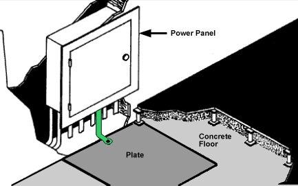
The preferred connection is with a braided strap. If a braided strap is not available, the connection should consist of no. 12 AWG (3.3 mm or 0.0051 in.) or larger conductor and should not be more than 1.5 m (5 ft) long. To minimize this length, the preferred connection of this braided strap or conductor is to the nearest portion of the enclosure on the panel, if the enclosure is electrically continuous from the green-conductor common point to this point of connection.
The raised-floor-supporting substructure can be used as a substitute for the transient plate if the structure has a consistently low-impedance path. If the raised floor has stringers or other subframing that makes electrical connection between the pedestals, the floor itself can be used for the signal reference plane. Some raised floors are stringerless and the floor tiles lock into isolated pedestals by gravity alone. If there is no reliable electrical connection between the pedestals, a signal reference grid can be constructed by connecting the pedestals together with conductors. A minimal grid would interconnect every other pedestal in the immediate area of the power panel and extend at least 3 m (10 ft) in all directions.
Transient grounding using the raised floor support structure

Figure 4. Signal reference grid

Stranded bare or insulated conductor of at least no. 8 AWG (8 mm or 0.0124 in.) copper is required. This conductor provides a low-impedance path and is strong enough to make physical damage unlikely. Any connection method is acceptable as long as it provides a reliable electrical and mechanical connection.
A customer's self-contained, separately derived power system (computer power centers, transformers, motor generators), installed on a raised floor, has the same requirements.
Voltage and frequency limits
Voltage and frequency limits must be maintained to ensure proper functioning of your system.
The phase-to-phase steady-state voltage must be maintained within plus six percent to minus 10 percent of the normal rated voltage, measured at the receptacle when the system is operating. A voltage surge or sag condition must not exceed plus 15 percent or minus 18 percent of the nominal voltage and must return to within a steady-state tolerance of plus 6 percent or minus 10 percent of normal rated voltage within 0.5 second.
Some systems might require special considerations and might have more or less restrictive specifications. See the individual system specifications for actual requirements. Because of the possibility of brownouts (planned voltage reduction by the utility company) or other marginal voltage conditions, installing a voltage monitor might be advisable.
The phase frequency must be maintained at 50 or 60 Hz + 0.5 Hz.
The value of any of the three phase-to-phase equipment voltages in the three-phase system must not differ by more than 2.5 percent from the arithmetic average of the three voltages. All three line-to-line voltages must be within the limits previously specified.
The maximum total harmonic content of the power system voltage waveforms on the equipment feeder must not exceed 5 percent with the equipment operating.
Power load
A preliminary sizing for total power load can be obtained by adding the total power requirements for all devices to be connected.
For a more precise analysis of power distribution system requirements, you can request an IBM System Power Profile Program printout from your seller. The System Power Profile Program, controlled and operated by the service office installation planning representative, provides a vector analysis rather than an arithmetic summation of total power. The vector analysis takes into consideration power factor and phase relationships. In addition, it considers waveform distortions caused by the load and inrush requirements. Additional capacity should be planned for future expansion. Contact your service office installation planning representative for information on how to obtain a System Power Profile.
Primary power problem areas
Your system is designed to operate on the normal power supplied by most electrical utility companies. However, possible computer malfunctions can be caused by outside (radiated or conducted) transient electrical noise signals being superimposed on the power line to the computer. To guard against this interference, power distribution design should comply with the specifications discussed in this topic.
Failures caused by the power source are basically of three types:
- Power line disturbances, such as, short duration dips in voltage as well as prolonged outages. If the frequency of such power failures is not acceptable for your operation, installing standby or buffered power might be necessary.
- Transient electrical noise superimposed on power lines might be caused by a variety of industrial, medical, communication, or other equipment:
- Within the computing facilities
- Adjacent to the computing facilities
- In the vicinity of the power company's distribution lines
Switching large electrical loads can cause problems, even though the source is on a different branch circuit. If you suspect such a condition, it might be advisable to provide a separate, dedicated feeder or transformer for your system directly from your power source.
If the transient-producing devices have been eliminated from the feeder and the computer room power panel and power line disturbances are still present, it might be necessary for you to install isolation equipment (for example, transformers, motor generators, or other power conditioning equipment).
Lightning protection
Install lightning protection devices is recommended on the computer power source when:
- The primary power is supplied by an overhead power service.
- The utility company installs lightning protectors on the primary power source.
- The area is subject to electrical storms or an equivalent type of power surge.
Lightning protection for communication wiring
Be sure to install lightning protection devices to protect communication wiring and equipment from surges and transients induced into the communication wiring. In any area subject to lightning, surge suppressors should be installed at each end of every outdoor cable installation, whether installed above the ground (aerial) or buried below the ground.
Information about lightning surge suppressors for communication wiring systems and recommended installation methods for outdoor communication cables can be found in the manuals for the specific type of data processing system that is being considered.
Power source
These guidelines help to ensure that your data center has a quality power source.
The primary power source is normally a wye-type or delta-type, three-phase service coming from a service entrance or a separately derived source with appropriate overcurrent protection and suitable ground (service entrance or building ground). A three-phase, five-wire power distribution system should be provided for flexibility in your data processing installation. However, depending on the type of equipment installed, a single-phase distribution system might be sufficient. The five wire system enables you to provide power for three-phase line-to-line, single phase line-to-line, and single phase line-to-neutral. The five wires consist of three phase conductors, one neutral conductor, and one insulated equipment grounding conductor (green, or green with yellow trace).
Conduit must not be used as the only grounding means.
Power panel feeders
Ensure that the feeder wires to the branch-circuit distribution panel are large enough to handle the total system power load. For optimal results, ensure that these feeders service no other loads.
Branch circuits
The computer branch circuit panel should be in an unobstructed, well-lighted area in the computer room.
The individual branch circuits on the panel should be protected by suitable circuit breakers properly rated according to manufacturer specifications and applicable codes. Each circuit breaker should be labeled to identify the branch circuit it is controlling. The receptacle should also be labeled.
Where a branch circuit and receptacle are installed to service your system, it is recommended that the grounding conductor of the branch circuit be insulated and equal in size to the phase conductors. The grounding conductor is an insulated, dedicated-equipment-grounding conductor, not the neutral.
Branch circuit receptacles installed under a raised floor should be within 0.9 m (3 ft) of the system that they supply power to. If the branch circuits are contained in a metallic conduit, either rigid or nonrigid, the conduit system should be grounded. This is accomplished by bonding the conduit to the power distribution panel, which in turn, is tied to the building or transformer ground.
Power cords are supplied in 4.3 m (14 ft) lengths unless otherwise noted in the system specifications. The length is measured from the exit symbol on the plan views. Some power plugs furnished by your seller are watertight, and should be located under the computer room raised floor.
Phase rotation
The three-phase power receptacles for some equipment, such as printers, must be wired for correct phase rotation. When looking at the face of the receptacle and counting clockwise from the ground pin, the sequence is phase 1, phase 2, and phase 3.
Emergency power control
A disconnecting means should be provided to disconnect the power from all electronic equipment in the computer room. This disconnecting means should be controlled from locations readily accessible to the operator at the principal exit doors. A similar disconnecting means to disconnect the air conditioning system serving this area should be available. Consult the local and national codes to determine the requirements for your installation. National Electric Code (NFPA 70) article 645 provides the requirements for this room EPO.
Convenience outlets
A suitable number of convenience outlets should be installed in the computer room and the Service Representative area for use by building maintenance personnel and service representatives. Convenience outlets should be on the lighting or other building circuits, not on the computer power panel or feeder. Under no circumstances are the service convenience outlets on your systems to be used for any purpose other than normal servicing.
Dual-power installation configurations
These dual-power installation configurations allow you to leverage the fully-redundant power features of your system.
Some models are designed with a fully redundant power system. The possible power installation configurations are listed as follows.
Dual-power installation: Redundant distribution panel and switch
This configuration requires that the system receives power from two separate power distribution panels. Each distribution panel receives power from a separate piece of building switch gear. This level of redundancy is not available in most facilities.
Figure 1. Dual power installation - Redundant distribution panel and switch

Dual-power installation: Redundant distribution panel
This configuration requires that the system receives power from two separate power distribution panels. The two distribution panels receive power from the same piece of building switch gear. Most facilities should be able to achieve this level of redundancy.
Figure 2. Dual power installation - Redundant distribution panel

Single distribution panel: Dual circuit breakers
This configuration requires that the system receives power from two separate circuit breakers in a single power panel. This configuration does not make full use of the redundancy provided by the processor. It is, however, acceptable if a second power distribution panel is not available.
Figure 3. Single distribution panel - Dual circuit breakers

>Air conditioning determination
The air conditioning system must provide year-round temperature and humidity control as a result of the heat dissipated during equipment operation.
Heat dissipation ratings are given in the server specifications for each server. Air conditioning units should not be powered from the computer power panel because of the high starting current drawn by their compressor units. The feeder line for the air conditioning system and the computer room power should not be in the same conduit.
Consider the following factors when determining the air conditioning capacity necessary for installation:
- Information technology equipment heat dissipation
- Number of personnel
- Lighting requirements
- Amount of fresh air introduced
- Possible reheating of circulated air
- Heat conduction through outer walls and windows
- Ceiling height
- Area of floors
- Number and placement of door openings
- Number and height of partitions
Most servers are air-cooled by internal blowers. A separate air conditioning system is recommended for data processing installation. A separate system might be required for small systems or individual servers intended for operation when the building air conditioning system is not adequate or is not operational. Server heat dissipation loads are given on the server specifications for each server. See the environmental requirements in the server specifications for your server.
General guidelines for data centers
Use these general guidelines to set up your data center.
Refer to the latest ASHRAE publication, "Thermal Guidelines for Data Processing Environments", dated 2011. This document can be purchased online at ashrae.org. A dedicated section outlines a detailed procedure for assessing the overall cooling health of the data center and optimizing for maximum cooling.
System and storage considerations
Most systems and storage products are designed to pull chilled air through the front of the system and exhaust hot air out of the back. The most important requirement is to ensure that the inlet air temperature to the front of the equipment does not exceed IBM environmental specifications. See the environmental requirements in the system specifications or hardware specification sheets. Make sure that the air inlet and exit areas are not blocked by paper, cables, or other obstructions. When upgrading or repairing your system, be sure not to exceed, if specified, the maximum allowed time for having the cover removed with the unit running. After your work is completed, be sure to reinstall all fans, heat sinks, air baffles, and other devices according to the documentation.
Manufacturers, including IBM, are reporting heat loads in a format suggested by the ASHRAE publication, "Thermal Guidelines for Data Processing Environments", dated 2011. Although this data is meant to be used to for heat load balancing, care is required when using the data to balance cooling supply and demand as many applications are transient and do not dissipate constant rates of heat. A thorough understanding of how the equipment and application behave with regard to heat load, including considerations for future growth, is required.
Room considerations
Data centers designed and built in the last 10 years are typically capable of cooling up to 3KW of heat load per cabinet. These designs often involve raised floor air distribution plenums 18 to 24 inches in height, room ceiling heights of 8 to 9 feet, and Computer Room Air Conditioning (CRAC) units distributed around the perimeter of the room. IT equipment occupies roughly 30-35% of the total data center space. The remaining space is white space (for example, access aisles, service clearances), power distribution units (PDUs), and CRAC units. Until recently, little attention has been given to heat load assessments, equipment layout and air delivery paths, heat load distribution, and floor tile placement and openings.
Assessing the total heat load of your installation
A total heat load assessment should be conducted to determine your overall environment balance point. The purpose of the assessment is to see if you have enough sensible cooling, including redundancy, to handle the heat load that you plan to install or have installed. There are several ways to perform this assessment, but the most common is to review the heat load and cooling in logical sections defined by I-beams, airflow blockages, or CRAC unit locations.
Equipment layout and air delivery paths
The hot-aisle, cold-aisle arrangement that is explained in the ASHRAE publication, "Thermal Guidelines for Data Processing Environments", dated 2011, should be used. In the following figure, racks within the data center are arranged such that there are cold aisles and hot aisles. The cold aisle consists of perforated floor tiles separating two rows of racks. The chilled air from the perforated floor tiles is exhausted from the tiles and is drawn into the fronts of the racks. The inlets of each rack (front of each rack) face the cold aisle. This arrangement allows the hot air exhausting the rear of the racks to return to the CRAC units; thus, minimizing hot exhaust air from the rack circulating back into the inlets of the racks. CRAC units are placed at the end of the hot aisles to facilitate the return of the hot air to the CRAC unit and maximize static pressure to the cold aisle.
The key to heat load management of the data center is to provide inlet air temperatures to the rack that meet the manufacturer's specifications. Because the chilled air exhausting from the perforated tiles in the cold aisle may not satisfy the total chilled airflow required by the rack, additional flow will be drawn from other areas of the raised floor and may not be chilled.
In many cases, the airflow drawn into the top of the rack, after the bottom of the rack has been satisfied, will be a mixture of hot air from the rear of the system and air from other areas. For those racks that are at the ends of a row, the hot airflow that exhausts from the rear of the rack and migrate to the front around the sides of the rack. These flow patterns have been observed in actual data centers and in flow modeling.

For a data center that may not have the best chilled-air-flow distribution, the following figure gives guidance in providing adequate chilled airflow given a specific heat load. The chart takes into account worst-case locations in a data center and are the requirements to meet the maximum temperature specifications required by most IBM high-end equipment. Altitude corrections are noted in the lower portion of the chart.

Heat load distribution
Increased performance capabilities and the accompanying heat load demands have caused data centers to have hot spots in the vicinity of heat loads that exceed 3KW. Facility owners are discovering that it is becoming increasingly difficult to plan cooling schemes for large-scale deployments of high-heat-load equipment. Essentially, two different approaches can be undertaken for a large-scale, high-end system or storage deployment:
- Provide ample cooling for maximum heat load requirements across the entire data center.
- Provide an average amount of cooling across the data center with the capability to increase cooling in limited, local areas.
Option 1 is very expensive and more conducive to new construction. For option 2, a number of things can be done to optimize cooling in existing data centers and possibly raise the cooling capability in limited sections.
One recommendation is to place floor tiles with high percent-open and flow ratings in front of the high-end racks. Another recommendation is to provide special means for removing hot exhaust air from the backs of the high-end racks immediately, before it has a chance to migrate back to the air intakes on racks in other parts of the room. This could be accomplished by installing special baffling or direct ducting back to the air returns on the CRAC units. Careful engineering is required to ensure that any recommendation does not have an adverse effect on the dynamics of the underfloor static pressure and airflow distribution.
In centers where floor space is not an issue, it would be most practical to design the entire raised floor to a constant level of cooling and depopulate racks or observe a greater distance between racks in order to meet the per-cabinet capability of the floor.
Floor tile placement and openings
Perforated tiles should be placed exclusively in the cold aisles, aligned with the intakes of the equipment. No perforated tiles should be placed in the hot aisles, no matter how uncomfortably hot. Hot aisles are, by design, supposed to be hot. Placement of open tiles in the hot aisle artificially decreases the return air temperature to the CRAC units, thereby reducing their efficiency and available capacity. This phenomenon contributes to hot spot problems in the data center. Perforated tiles should not be placed in too close proximity to the CRAC units. In areas under the raised floor where air velocities exceed about 530 feet-per-minute, usually within about six tiles of the unit discharges, a Venturi effect may be created where room air will be sucked downward into the raised floor, opposite of the desired result of upward chilled air delivery.
The volumetric flow capabilities of floor tiles with various percent-open ratings are shown in the following figure.
Volumetric flow capabilities of various raised floor tiles

Floor tiles in typical data centers deliver between 100 and 300 cfm. By optimizing the flow characteristics it might be possible to realize flows as high as 500 cfm. Flow rates as high as 700-800 cfm per tile are possible with tiles with the highest percent-open rating. Floor tiles must be aligned in the cold aisles with the intake locations on the equipment.
Openings in the raised-floor that are not there for the purpose of delivering chilled air directly to the equipment in the data center space should be completely sealed with brush assemblies or other cable opening material (for example, foam sheeting, fire pillows). Other openings that must be sealed are holes in data center perimeter walls, underfloor, and ceiling. Sealing all openings will help maximize under-floor static pressure, ensure optimal airflow to the cold aisles where it is needed, and eliminate short-circuiting of unused air to the CRAC unit returns.
Environmental design criteria
Use these environmental design criteria to ensure that your data center environment provides optimal conditions for your server operation.
The following environmental specifications are based on an altitude 1800 m (5906 ft above sea level). Some systems have more restrictive requirements on temperature, moisture, and altitude.
Airborne particulates (including metal flakes or particles) and reactive gases acting alone or in combination with other environmental factors, such as humidity or temperature, might pose a risk to the server. Risks that are posed by the presence of excessive particulate levels or concentrations of harmful gases include damage that might cause the server to malfunction or cease functioning altogether. The environmental specifications set forth limits for particulates and gases that are intended to avoid such damage. The limits must not be viewed or used as definitive limits because numerous other factors, such as temperature or moisture content of the air, can influence the impact of particulates or environmental corrosives and gaseous contaminant transfer. In the absence of specific limits that are set forth in the environmental specifications, you must implement practices that maintain particulate or gas levels that are consistent with the protection of human health and safety. If IBM determines that the levels of particulates or gases in your environment have caused damage to the server, IBM might limit or restrict the provision of repair or replacement of servers or parts on the implementation of appropriate remedial measures to mitigate such environmental contamination. Implementation of such remedial measures is a customer responsibility.
| Environment | Value |
|---|---|
| Temperature | 18°C (64.4°F) . 27°C (80.6°F)4 |
| Low-end moisture | 5.5°C (41.9°F) dew point |
| High-end moisture | 60% relative humidity or 15°C (59°F) dew point |
| Gaseous contamination | Severity level G1 as per ANSI/ISA 71.04-19852, which states that the reactivity rate of copper coupons shall be less than 300 Angstroms per month (Åmonth, . 0.0039 .g/cm2-hour weight gain).6 In addition, the reactivity rate of silver coupons shall be less than 300Åmonth (. 0.0035 .g/cm2-hour weight gain).7 The reactive monitoring of gaseous corrosivity must be conducted approximately 5 cm (2 in.) in front of the rack on the air inlet side at one-quarter and three-quarter frame height off the floor or where the air velocity is much higher. |
| Particulate contamination | Data centers must meet the cleanliness level
of ISO 14644-1 class 8. For data centers without airside economizer,
the ISO 14644-1 class 8 cleanliness might be met by choosing one of the following filtration methods:
For data centers with airside economizers, the choice of filters to achieve ISO class 8 cleanliness depends on the specific conditions present at that data center. The deliquescent relative humidity of the particulate contamination should be more than 60% RH.3 Data centers must be free of zinc whiskers.8 |
The class 1 and class 2 temperature and moisture limits, measured at the IT equipment air inlet, are from ASHRAE Thermal Guidelines for Data Processing Environments, second edition (2009). Maximum recommended ambient temperature reduces 1°C (1.8°F) for every 300 m (984 ft) over 1800 m (5906 ft). The ASHRAE class 1 allowable ranges are 15°C . 32°C, 20% . 80% relative humidity, and the class 2 allowable ranges are 10°C . 35°C, 20% . 80% relative humidity. For extended periods of time, IT manufacturers recommend that data center operators maintain the recommended environment for maximum reliability. The allowable environment is where IT manufacturers test their equipment operation to verify that the equipment operates. This is not a statement of reliability, but one of functional IT equipment.
ANSI/ISA-S71.04. 1985. Environmental conditions for process measurement and control systems: Airborne contaminants, Instrument Society of America, Research Triangle Park, NC, 1985.
The deliquescent relative humidity of particulate contamination is the relative humidity at which the dust absorbs enough water to become wet and promote ionic conduction.
For ambient temperatures exceeding 25°C (77°F), the acoustical noise levels of the system might increase as the speed of the air-moving devices increases.
The IT equipment acclimation period is 1 hour per 20°C (68°F) of temperature change from the shipping environment to the operating environment.
The derivation of the equivalence between the rate of copper corrosion growth in the thickness of the corrosion product in month and the rate of weight gain assumes that Cu2S and Cu2O grow in equal proportions.
tape on a metal stub. If examination of the sticky tape in a scanning electron microscope reveals no zinc whiskers, the data center is considered free of zinc whiskers.
Nonoperating environment2
| Environment | Value |
|---|---|
| Temperature | 5°C (41°F) . 45°C (113°F) |
| Relative humidity | 8% . 80% |
| Dew point | Less than 27°C (81°F) |
| Gaseous contamination | Severity level G1 as per ANSI/ISA 71.04-19851, which states that the reactivity rate of copper coupons shall be less than 300 Angstroms per month (Åmonth, . 0.0039 .g/cm2-hour weight gain).3 In addition, the reactivity rate of silver coupons shall be less than 300Åmonth (. 0.0035 .g/cm2-hour weight gain).4 The reactive monitoring of gaseous corrosivity should be conducted approximately 2 in. (5 cm) in front of the rack on the air inlet side at one-quarter and three-quarter frame height off the floor or where the air velocity is much higher. |
Notes:
- ANSI/ISA-S71.04. 1985. Environmental conditions for process measurement and control systems: Airborne contaminants, Instrument Society of America, Research Triangle Park, NC, 1985.
- The IT equipment acclimation period is 1 hour per 20°C (68°F) of temperature change from the shipping environment to the operating environment.
- The derivation of the equivalence between the rate of copper corrosion growth in the thickness of the corrosion product in Åmonth and the rate of weight gain assumes that Cu2S and Cu2O grow in equal proportions.
- The derivation of the equivalence between the rate of silver corrosion growth in the thickness of the corrosion product in Åmonth and the rate of weight gain assumes that Ag2S is the only corrosion product.
| Environment | Value |
|---|---|
| Temperature | -40°C (-40°F) . 60°C (140°F) |
| Relative humidity | 5% . 100% (no condensation) |
| Wet bulb | Less than 29°C (84.2°F) |
| Shipping package | IBM-approved vapor barrier bag with desiccant |
| Environment | Value |
|---|---|
| Temperature | 1 degree C (33.8°F) . 60°C (140°F) |
| Relative humidity | 5% . 80% (no condensation) |
| Wet bulb | Less than 29°C (84.2°F) |
| Shipping package | IBM-approved vapor barrier bag with desiccant |
Air quality
Many systems are installed in environments other than the typical data center, business office, or clean industrial location. These environments might exhibit various temperatures, relative humidity, and levels of airborne particles or corrosive gases. IBM systems are designed to work within the environmental specifications shown in the previous tables unless otherwise noted on an individual system specification.
An environment is considered unacceptable when the temperature, relative humidity, corrosive gases, or solid particles in the air exceed specific limits set by IBM. Equipment that operates in environments classified as unacceptable might be subject to degraded performance and permanent damage if the equipment is not designed for such environments.
Contaminants
Systems are being installed in increasingly diversified industries. Some of these industries, as a by-product of their processes, cause the atmosphere to contain measurable quantities of gases and solid particles that are potentially harmful to electronic equipment. Urban areas that are highly industrialized might have levels of gases and solid particles that cause an unacceptable environment exposure to exist throughout an entire area.
IBM is concerned with two classes of atmospheric contaminants: solid particles and gases. Solid particles in the air are referred to as particulates. Water vapor can combine with these tiny, solid particles and form compounds. Such matter is said to be hygroscopic. It can be harmful, depending on the particulate composition. Gases can form harmful acids or bases when combined with water. Because of the ability to absorb moisture, the relative humidity and temperature are significant factors in an unacceptable environment.
High concentrations of gases, such as sulfur dioxide, nitrogen dioxide, ozone, and acidic gaseous chlorine, which are associated with industrial processes, are known to cause corrosion and failure of electronic components. In addition to gases, some industrial processes produce particulate contamination. These particles can settle (in the form of dust) in surrounding areas even though the process producing the particles might be some distance away.
Industries engaged in processing petroleum, chemicals, primary metals, food, mining, and paper have a higher probability of encountering an unacceptable environment. However, contamination can be a result of construction, cleaning, or other activities that can occur anywhere.
A visual inspection is the first step in determining the likelihood of contamination. Some indicators of an unacceptable environment might include corrosion of metal, such as door handles and hinges. Often, the presence of contaminants can be determined by odor as in the case of chlorine or sulfur, which have a distinctive smell. Observe whether a heavy layer of dust settles on surfaces, especially in the primary metals industry. This dust is often conductive and can create electrical arcing or short circuits if drawn into electronic equipment.
To determine adherence to IBM requirements for gases and particulates, laboratory techniques are necessary. Testing for gases and particulates involves special equipment and procedures. Contact the IBM installation planning representative for guidance.
If the environment is contaminated, IBM can also provide guidance on remediation, prevention, and control. Recommended solutions might include, but are not limited to, room pressurization, tighter relative humidity control, filtration, maintenance, and monitoring.
System specifications
System specifications provide detailed information for your system, including dimensions, electrical, power, temperature, environmental requirements, and noise emissions.
Model 8283-12X system specifications
System specifications provide detailed information for IBM 8283-12X systems including dimensions, electrical data, power, temperature, environmental requirements, and noise emissions.
Dimensions
| Width | Depth | Height | Weight | EIA units |
|---|---|---|---|---|
| 610 mm (24 in) | 1000 mm (39.4 in) | 1240 mm (49 in) | 365.6 kg (815 lb) | 25 |
Electrical
| Electrical characteristics | Properties |
|---|---|
| Maximum kVA | 5.79 kVA |
| Voltage1 | 200 - 240 (nominal) V ac |
| Frequency | 50 Hz or 60 Hz |
| Maximum thermal output | 18.2 kBTU/hr |
| Maximum power consumption2 | 5.5 kW |
| Phase | 1 |
|
1 All drawers mounted in the system are rated 200 - 240 V ac. The power supplies automatically accept any voltage within the rated voltage range. With dual power supplies installed and operating, the power supplies draw approximately equal current from the utility (mains) and provide approximately equal current to the load. 2 When planning the electrical system, it is important to use maximum values to account for internal or environmental conditions that result in power consumption increasing beyond typical values. However, when planning for heat load, you can use the typical value of 4.68 kW. | |
Environment requirements
| Environment | Recommended operating | Allowable operating | Non-operating |
|---|---|---|---|
| ASHRAE class | | A2 | |
| Airflow direction1 | | Front-to-back | |
| Temperature2 | 18°C - 27°C (64°F - 80°F) | 5°C - 40°C (41°F - 104°F) | 5°C - 45°C (41°F - 113°F) |
| Humidity range | 5.5°C (42°F) dew point (DP) to 60% relative humidity (RH) and 15°C (59°F) dew point | -12.0°C (10.4°F) DP and 8% - 85% RH | 8% - 85% RH |
| Maximum dew point | | 24°C (75°F) | 27°C (80°F) |
| Maximum operating altitude | | 3050 m (10000 ft) | |
| Shipping temperature | | | -40°C - 60°C (-40°F - 140°F) |
| Shipping relative humidity | | | 5% - 100% |
|
1Nominal cubic feet per minute (CFM) is approximately 1110. Maximum CFM is approximately 2105. 2Derate maximum allowable dry-bulb temperature 1°C/175 m above 950 m. | |||
Electromagnetic compatibility compliance
The electromagnetic compatibility compliance is: FCC 47 CFR Part 15, ICES-003, EN 55022, EN 55024, CISPR-22, AS/NZS CISPR-22, CNS 13438, VCCI, GB 9254.
Product safety compliance
The product safety compliance is: IEC 60950-1; UL 60950-1; CSA 60950-1.
Delivery and subsequent transportation of the equipment
You must prepare your environment, with assistance from an authorized service provider, to accept the new product based on the installation planning information provided. In anticipation of the equipment delivery, prepare the final installation site in advance so that professional movers or riggers can transport the equipment to the final installation site within the computer room. If, for some reason, this is not possible at the time of delivery, you must make arrangements to have professional movers or riggers return to finish the transportation at a later date. Only professional movers or riggers should transport the equipment. The authorized service provider can only perform minimal frame repositioning within the computer room, as needed, to perform required service actions. You are also responsible for using professional movers or riggers when you relocate or dispose of equipment.
System specifications provide detailed information for IBM 8283-14X systems including dimensions, electrical data, power, temperature, environmental requirements, and noise emissions.
Dimensions
| Width | Depth | Height | Weight | EIA units |
|---|---|---|---|---|
| 610 mm (24 in) | 1000 mm (39.4 in) | 1240 mm (49 in) | 385.6 kg (850 lb) | 25 |
Electrical
| Electrical characteristics | Properties |
|---|---|
| Maximum kVA | 6.84 kVA |
| Voltage1 | 200 - 240 V ac |
| Frequency | 50 Hz or 60 Hz |
| Maximum thermal output | 21.45 kBTU/hr |
| Maximum power consumption2 | 6.5 kW |
| Phase | 1 |
|
1 All drawers mounted in the system are rated 200 - 240 V ac. The power supplies automatically accept any voltage within the rated voltage range. With dual power supplies installed and operating, the power supplies draw approximately equal current from the utility (mains) and provide approximately equal current to the load. 2 When planning the electrical system, it is important to use maximum values to account for internal or environmental conditions that result in power consumption increasing beyond typical values. However, when planning for heat load, you can use the typical value of 5.52 kW. | |
Environment requirements
| Environment | Recommended operating | Allowable operating | Nonoperating |
|---|---|---|---|
| ASHRAE class | | A2 | |
| Airflow direction1 | | Front-to-back | |
| Temperature2 | 18°C - 27°C (64°F - 80°F) | 5°C - 40°C (41°F - 104°F) | 5°C - 45°C (41°F - 113°F) |
| Humidity range | 5.5°C (42°F) dew point (DP) to 60% relative humidity (RH) and 15°C (59°F) dew point | -12.0°C (10.4°F) DP and 8% - 85% RH | 8% - 85% RH |
| Maximum dew point | | 24°C (75°F) | 27°C (80°F) |
| Maximum operating altitude | | 3050 m (10000 ft) | |
| Shipping temperature | | | -40°C - 60°C (-40°F - 140°F) |
| Shipping relative humidity | | | 5% - 100% |
|
1Nominal cubic feet per minute (CFM) is approximately 1110. Maximum CFM is approximately 2105. 2Derate maximum allowable dry-bulb temperature 1°C/175 m above 950 m. | |||
Electromagnetic compatibility compliance
The electromagnetic compatibility compliance is: FCC 47 CFR Part 15, ICES-003, EN 55022, EN 55024, CISPR-22, AS/NZS CISPR-22, CNS 13438, VCCI, GB 9254.
Product safety compliance
The product safety compliance is: IEC 60950-1; UL 60950-1; CSA 60950-1.
Delivery and subsequent transportation of the equipment
You must prepare your environment, with assistance from an authorized service provider, to accept the new product based on the installation planning information provided. In anticipation of the equipment delivery, prepare the final installation site in advance so that professional movers or riggers can transport the equipment to the final installation site within the computer room. If, for some reason, this is not possible at the time of delivery, you must make arrangements to have professional movers or riggers return to finish the transportation at a later date. Only professional movers or riggers should transport the equipment. The authorized service provider can only perform minimal frame repositioning within the computer room, as needed, to perform required service actions. You are also responsible for using professional movers or riggers when you relocate or dispose of equipment.
Model 8283-3C2 system specifications
System specifications provide detailed information for IBM 8283-3C2 systems including dimensions, electrical data, power, temperature, environmental requirements, and noise emissions.
Dimensions
| Width | Depth | Height | Weight | EIA units |
|---|---|---|---|---|
| 0.644 m (25.4 in) | 1.098 m (43.3 in) | 2.015 m (79.3 in) | 936 Kg (2027 lb) | 42 EIA units |
| 1 The system is equivalent to a 7014-T42 system with PureApplication System doors. For more information on the 7014 system, see Model 7014-T42, 7014-B42, and 0553. | ||||
Electrical
| Electrical characteristics | Properties |
|---|---|
| Maximum kVA | 14.173 kVA |
| Voltage1,2 | 200 - 208 and 380 - 415 V ac |
| Frequency | 47 - 63 Hz |
| Maximum thermal output | 47692 BTU/hr |
| Maximum power consumption3 | 7.9 kW |
| Phase | 3 |
|
1 The input voltage is based on the power distribution unit (PDU) and associated line cord. In countries that support line-to-line 200 - 208 V ac, the PDU input voltage matches the PDU output voltage. In countries that support line-to-line 380 - 415 V ac, the PDU output voltage is in the range of 220 - 240 V ac.
2 All drawers mounted in the system are rated 200 - 240 V ac. The power supplies automatically accept any voltage within the rated voltage range. With dual power supplies installed and operating, the power supplies draw approximately equal current from the utility (mains) and provide approximately equal current to the load. 3 When planning the electrical system, it is important to use maximum values to account for internal or environmental conditions that result in power consumption increasing beyond typical values. However, when planning for heat load, you can use the typical value of 5.9 kW. | |
Environment requirements
| Environment | Recommended operating | Allowable operating | Nonoperating |
|---|---|---|---|
| ASHRAE class | | A2 | |
| Airflow direction1 | | Front-to-back | |
| Temperature2 | 18°C - 27°C (64°F - 80°F) | 5°C - 40°C (41°F - 104°F) | 5°C - 45°C (41°F - 113°F) |
| Humidity range | 5.5°C (42°F) dew point (DP) to 60% relative humidity (RH) and 15°C (59°F) dew point | -12.0°C (10.4°F) DP and 8% - 85% RH | 8% - 85% RH |
| Maximum dew point | | 24°C (75°F) | 27°C (80°F) |
| Maximum operating altitude | | 3050 m (10000 ft) | |
| Shipping temperature | | | -40°C - 60°C (-40°F - 140°F) |
| Shipping relative humidity | | | 5% - 100% |
|
1Nominal cubic feet per minute (CFM) is approximately 1110. Maximum CFM is approximately 2105. 2Derate maximum allowable dry-bulb temperature 1°C/175 m above 950 m. | |||
Electromagnetic compatibility compliance
The electromagnetic compatibility compliance is: FCC 47 CFR Part 15, ICES-003, EN 55022, EN 55024, CISPR-22, AS/NZS CISPR-22, CNS 13438, VCCI, GB 9254.
Product safety compliance
The product safety compliance is: IEC 60950-1; UL 60950-1; CSA 60950-1.
Delivery and subsequent transportation of the equipment
You must prepare your environment, with assistance from an authorized service provider, to accept the new product based on the installation planning information provided. In anticipation of the equipment delivery, prepare the final installation site in advance so that professional movers or riggers can transport the equipment to the final installation site within the computer room. If, for some reason, this is not possible at the time of delivery, you must make arrangements to have professional movers or riggers return to finish the transportation at a later date. Only professional movers or riggers should transport the equipment. The authorized service provider can only perform minimal frame repositioning within the computer room, as needed, to perform required service actions. You are also responsible for using professional movers or riggers when you relocate or dispose of equipment.
Model 8283-3F2 system specifications
System specifications provide detailed information for IBM 8283-3F2 systems, including dimensions, electrical data, power, temperature, environmental requirements, and noise emissions.
Dimensions
| Width | Depth | Height | Weight | EIA units |
|---|---|---|---|---|
| 0.644 m (25.4 in) | 1.098 m (43.3 in) | 2.015 m (79.3 in) | 953 Kg (2095 lb) | 42 EIA units |
| 1 The system is equivalent to a 7014-T42 system with PureApplication System doors. For more information on the 7014 system, see Model 7014-T42, 7014-B42, and 0553. | ||||
Electrical
| Electrical characteristics | Properties |
|---|---|
| Maximum kVA | 18.324 kVA |
| Voltage1,2 | 200 - 208 and 380 - 415 V ac |
| Frequency | 47 - 63 Hz |
| Maximum thermal output | 59399 BTU/hr |
| Maximum power consumption3 | 10.4 kW |
| Phase | 3 |
|
1 The input voltage is based on the power distribution unit (PDU) and associated line cord. In countries that support line-to-line 200 - 208 V ac, the PDU input voltage matches the PDU output voltage. In countries that support line-to-line 380 - 415 V ac, the PDU output voltage is in the range of 220 - 240 V ac.
2 All drawers mounted in the system are rated 200 - 240 V ac. The power supplies automatically accept any voltage within the rated voltage range. With dual power supplies installed and operating, the power supplies draw approximately equal current from the utility (mains) and provide approximately equal current to the load. 3 When planning the electrical system, it is important to use maximum values to account for internal or environmental conditions that result in power consumption increasing beyond typical values. However, when planning for heat load, you can use the typical value of 7.8 kW. | |
Environment requirements
| Environment | Recommended operating | Allowable operating | Nonoperating |
|---|---|---|---|
| ASHRAE class | | A2 | |
| Airflow direction1 | | Front-to-back | |
| Temperature2 | 18°C - 27°C (64°F - 80°F) | 5°C - 40°C (41°F - 104°F) | 5°C - 45°C (41°F - 113°F) |
| Humidity range | 5.5°C (42°F) dew point (DP) to 60% relative humidity (RH) and 15°C (59°F) dew point | -12.0°C (10.4°F) DP and 8% - 85% RH | 8% - 85% RH |
| Maximum dew point | | 24°C (75°F) | 27°C (80°F) |
| Maximum operating altitude | | 3050 m (10000 ft) | |
| Shipping temperature | | | -40°C - 60°C (-40°F - 140°F) |
| Shipping relative humidity | | | 5% - 100% |
|
1Nominal cubic feet per minute (CFM) is approximately 1280. Maximum CFM is approximately 2465. 2Derate maximum allowable dry-bulb temperature 1°C/175 m above 950 m. | |||
Electromagnetic compatibility compliance
The electromagnetic compatibility compliance is: FCC 47 CFR Part 15, ICES-003, EN 55022, EN 55024, CISPR-22, AS/NZS CISPR-22, CNS 13438, VCCI, GB 9254.
Product safety compliance
The product safety compliance is: IEC 60950-1; UL 60950-1; CSA 60950-1.
Delivery and subsequent transportation of the equipment
You must prepare your environment, with assistance from an authorized service provider, to accept the new product based on the installation planning information provided. In anticipation of the equipment delivery, prepare the final installation site in advance so that professional movers or riggers can transport the equipment to the final installation site within the computer room. If, for some reason, this is not possible at the time of delivery, you must make arrangements to have professional movers or riggers return to finish the transportation at a later date. Only professional movers or riggers should transport the equipment. The authorized service provider can only perform minimal frame repositioning within the computer room, as needed, to perform required service actions. You are also responsible for using professional movers or riggers when you relocate or dispose of equipment.
Model 8283-3L2 system specifications
System specifications provide detailed information for IBM 8283-3L2 systems, including dimensions, electrical data, power, temperature, environmental requirements, and noise emissions.
Dimensions
| Width | Depth | Height | Weight | EIA units |
|---|---|---|---|---|
| 0.644 m (25.4 in) | 1.098 m (43.3 in) | 2.015 m (79.3 in) | 1016 Kg (2232 lb) | 42 EIA units |
| 1 The system is equivalent to a 7014-T42 system with PureApplication System doors. For more information on the 7014 system, see Model 7014-T42, 7014-B42, and 0553. | ||||
Electrical
| Electrical characteristics | Properties |
|---|---|
| Maximum kVA | 25.547 kVA |
| Voltage1,2 | 200 - 208 and 380 - 415 V ac |
| Frequency | 47 - 63 Hz |
| Maximum thermal output | 82811 BTU/hr |
| Maximum power consumption3 | 15.4 kW |
| Phase | 3 |
|
1 The input voltage is based on the power distribution unit (PDU) and associated line cord. In countries that support line-to-line 200 - 208 V ac, the PDU input voltage matches the PDU output voltage. In countries that support line-to-line 380 - 415 V ac, the PDU output voltage is in the range of 220 - 240 V ac. 2 All drawers mounted in the system are rated 200 - 240 V ac. The power supplies automatically accept any voltage within the rated voltage range. With dual power supplies installed and operating, the power supplies draw approximately equal current from the utility (mains) and provide approximately equal current to the load. 3 When planning the electrical system, it is important to use maximum values to account for internal or environmental conditions that result in power consumption increasing beyond typical values. However, when planning for heat load, you can use the typical value of 11.6 kW. | |
Environment requirements
| Environment | Recommended operating | Allowable operating | Nonoperating |
|---|---|---|---|
| ASHRAE class | | A2 | |
| Airflow direction1 | | Front-to-back | |
| Temperature2 | 18°C - 27°C (64°F - 80°F) | 5°C - 40°C (41°F - 104°F) | 5°C - 45°C (41°F - 113°F) |
| Humidity range | 5.5°C (42°F) dew point (DP) to 60% relative humidity (RH) and 15°C (59°F) dew point | -12.0°C (10.4°F) DP and 8% - 85% RH | 8% - 85% RH |
| Maximum dew point | | 24°C (75°F) | 27°C (80°F) |
| Maximum operating altitude | | 3050 m (10000 ft) | |
| Shipping temperature | | | -40°C - 60°C (-40°F - 140°F) |
| Shipping relative humidity | | | 5% - 100% |
|
1Nominal cubic feet per minute (CFM) is approximately 1625. Maximum CFM is approximately 3185. 2Derate maximum allowable dry-bulb temperature 1°C/175 m above 950 m. | |||
Electromagnetic compatibility compliance
The electromagnetic compatibility compliance is: FCC 47 CFR Part 15, ICES-003, EN 55022, EN 55024, CISPR-22, AS/NZS CISPR-22, CNS 13438, VCCI, GB 9254.
Product safety compliance
The product safety compliance is: IEC 60950-1; UL 60950-1; CSA 60950-1.
Delivery and subsequent transportation of the equipment
You must prepare your environment, with assistance from an authorized service provider, to accept the new product based on the installation planning information provided. In anticipation of the equipment delivery, prepare the final installation site in advance so that professional movers or riggers can transport the equipment to the final installation site within the computer room. If, for some reason, this is not possible at the time of delivery, you must make arrangements to have professional movers or riggers return to finish the transportation at a later date. Only professional movers or riggers should transport the equipment. The authorized service provider can only perform minimal frame repositioning within the computer room, as needed, to perform required service actions. You are also responsible for using professional movers or riggers when you relocate or dispose of equipment.
Model 8283-3S2 system specifications
System specifications provide detailed information for IBM 8283-3S2 systems, including dimensions, electrical data, power, temperature, environmental requirements, and noise emissions.
Dimensions
| Width | Depth | Height | Weight | EIA units |
|---|---|---|---|---|
| 0.644 m (25.4 in) | 1.098 m (43.3 in) | 2.015 m (79.3 in) | 1088 Kg (2391 lb) | 42 EIA units |
| 1 The system is equivalent to a 7014-T42 system with PureApplication System doors. For more information on the 7014 system, see Model 7014-T42, 7014-B42, and 0553. | ||||
Electrical
| Electrical characteristics | Properties |
|---|---|
| Maximum kVA | 32.770 kVA |
| Voltage1,2 | 200 - 208 and 380 - 415 V ac |
| Frequency | 47 - 63 Hz |
| Maximum thermal output | 106225 BTU/hr |
| Maximum power consumption3 | 21.2 kW |
| Phase | 3 |
|
1 The input voltage is based on the power distribution unit (PDU) and associated line cord. In countries that support line-to-line 200 - 208 V ac, the PDU input voltage matches the PDU output voltage. In countries that support line-to-line 380 - 415 V ac, the PDU output voltage is in the range of 220 - 240 V ac. 2 All drawers mounted in the system are rated 200 - 240 V ac. The power supplies automatically accept any voltage within the rated voltage range. With dual power supplies installed and operating, the power supplies draw approximately equal current from the utility (mains) and provide approximately equal current to the load. 3 When planning the electrical system, it is important to use maximum values to account for internal or environmental conditions that result in power consumption increasing beyond typical values. However, when planning for heat load, you can use the typical value of 15.9 kW. | |
Environment requirements
| Environment | Recommended operating | Allowable operating | Nonoperating |
|---|---|---|---|
| ASHRAE class | | A2 | |
| Airflow direction1 | | Front-to-back | |
| Temperature2 | 18°C - 27°C (64°F - 80°F) | 5°C - 40°C (41°F - 104°F) | 5°C - 45°C (41°F - 113°F) |
| Humidity range | 5.5°C (42°F) dew point (DP) to 60% relative humidity (RH) and 15°C (59°F) dew point | -12.0°C (10.4°F) DP and 8% - 85% RH | 8% - 85% RH |
| Maximum dew point | | 24°C (75°F) | 27°C (80°F) |
| Maximum operating altitude | | 3050 m (10000 ft) | |
| Shipping temperature | | | -40°C - 60°C (-40°F - 140°F) |
| Shipping relative humidity | | | 5% - 100% |
|
1Nominal cubic feet per minute (CFM) is approximately 2030. Maximum CFM is approximately 4025. 2Derate maximum allowable dry-bulb temperature 1°C/175 m above 950 m. | |||
Electromagnetic compatibility compliance
The electromagnetic compatibility compliance is: FCC 47 CFR Part 15, ICES-003, EN 55022, EN 55024, CISPR-22, AS/NZS CISPR-22, CNS 13438, VCCI, GB 9254.
Product safety compliance
The product safety compliance is: IEC 60950-1; UL 60950-1; CSA 60950-1.
Delivery and subsequent transportation of the equipment
You must prepare your environment, with assistance from an authorized service provider, to accept the new product based on the installation planning information provided. In anticipation of the equipment delivery, prepare the final installation site in advance so that professional movers or riggers can transport the equipment to the final installation site within the computer room. If, for some reason, this is not possible at the time of delivery, you must make arrangements to have professional movers or riggers return to finish the transportation at a later date. Only professional movers or riggers should transport the equipment. The authorized service provider can only perform minimal frame repositioning within the computer room, as needed, to perform required service actions. You are also responsible for using professional movers or riggers when you relocate or dispose of equipment.
Power distribution unit and power cable specifications
Learn about the power distribution unit (PDU) and power cable specifications and configurations for the system.
Power distribution unit
Each system ships with four PDUs, which are either 7189 or 7196. The PDU model is determined according to the power standards of the geography in which the system is installed.
| Electrical characteristics | Properties | ||||
|---|---|---|---|---|---|
| Voltage | 100 - 240 V ac | 200 - 240 V ac | 200 - 240 V ac | 200 - 208 V ac | 380 - 415 V ac |
| Amps | 12 | 24 | 48 | 48 | 32 |
| kVA | 1.2 | 4.8 | 9.6 | 16.6 | 21.1 |
| Frequency | 50/60 Hz | 50/60 Hz | 50/60 Hz | 50/60 Hz | 50/60 Hz |
| Phase | 1 | 1 | 1 | 3 | 3 |
Power distribution unit and power cable configurations
- The PDU feature code 7196 comes with an attached power cable and 460P9W receptacle.
- The PDU feature code 7189 comes with one of the following power
cable and receptacle configurations:
- Line cord 6667 and 56P532 receptacle (Australia / New Zealand)
- Line cord 6489 and 532P6W receptacle
See the following table for power connectors and receptacles suitable for each plug:
Requisite power connectors and receptacles
Use the following summary to confirm plug and receptacle configurations:
IEC 309 pin & sleeve plug decode summary

Related information
See the IBM Flex System Enterprise Chassis Power Requirements Guide
Configuration requirements
Configure and administering IBM PureApplication System W1500 requires specific hardware, software, and personnel skills.
Cloud requirements
Your cloud configuration requires the following resources:
- Servers with a hypervisor installed
- Local or storage area network (SAN) storage
- A pool of available IP addresses that can be assigned to virtual systems
- IP address ranges to support the number of concurrent virtual machines to be deployed
- Credentials for the VMware ESX hypervisors to be used in the cloud
All hypervisors must be started before they are available to run in PureApplication System.
For Linux images, PureApplication System supports second extended (ext2), third extended (ext3), and fourth extended (ext 4) file system types, without encryption.
Skills required
To set up and administer the system, you need network administration skills. You also need technical familiarity with the hypervisors that you are using and any managers that are managing them.
Information required
Collect the following data to define your base configuration:
- The IP address and subnet mask for the Ethernet interface for system management access.
- The IP address of the default gateways that support the subnets for the Ethernet interfaces.
- The IP address of the Domain Name System (DNS) server. Ensure that the DNS server is configured for both forward and reverse look ups.
- Communication parameters for the serial interface: 9600 baud, 8 data bits, no parity bits, and 1 stop bit. (9600.8.n.1)
- Mail server information (SMTP) to set up email notifications.
- Network Time Protocol (NTP) server information for WAS cells to function.
- (Optional) The IP addresses and subnet mask for Ethernet interfaces for system service access, for example ETH0, ETH1, and ETH2.
Best Practice: For all network-wide and system-wide management functions, use the MGMT Ethernet interface on a dedicated subnet. The dedicated subnet handles network traffic for web management, using the web GUI, functions.
To handle data traffic to and from the various hypervisors, use the remaining Ethernet interfaces.
Administrative client requirements
You can administer PureApplication System with one of the following administrative clients:
| Command-line interface | Download the command-line interface. |
| Web user interface |
Microsoft Internet Explorer V8, V9, and V10.
Mozilla Firefox Extended Support Release (ESR) V17. Mozilla Firefox V22. Apple Safari V5.1 and later. |
Restriction: All other browsers are not supported and do not work with PureApplication System.
When using the Microsoft Internet Explorer browser on a Microsoft Windows Server, an error might occur when trying to open the system console. The Internet Explorer Enhanced Security Configuration is flagging the page as an untrusted web site and is blocking access. You can either add the website to the list of trusted sites or turn off Internet Explorer Enhanced Security Configuration. See the instructions provided by your version of Windows Server for details.
Supported middleware
IBM PureApplication System 1.0
The following middleware is supported:
- WebSphere Application Server 7.0.0.21 and later.
- WebSphere Application Server 8.0.0.3 and later.
IBM PureApplication System 1.0 is installed with the monitoring agent for WebSphere Application Server 1.0.
IBM PureApplication System 1.0.0.2
The following middleware is supported:
- WebSphere Application Server 7.0.0.21 and later.
- WebSphere Application Server 8.0.0.3 and later.
IBM PureApplication System 1.0.0.2 is installed with the monitoring agent for WebSphere Application Server 1.0.
IBM PureApplication System 1.0.0.4
The following middleware is supported:
- WebSphere Application Server 7.0.0.21 and later.
- WebSphere Application Server 8.0.0.3 and later.
- WebSphere Application Server 8.5.0.1 and later.
IBM PureApplication System 1.0.0.4 is installed with the monitoring agent for WebSphere Application Server 1.1.
Virtual system pattern requirements
Software requirements
IBM Foundation Pattern or later (includes shared services). This pattern type is included with the product.
In addition to these general pattern requirements, there might be additional pattern-specific requirements. For information about hardware and software requirements for virtual system patterns that are not covered in this topic, see the documentation for the specific pattern that you are using.
NTP and DNS servers
A configured NTP server, accessible by the virtual machines, is required to successfully deploy a virtual application pattern or virtual system pattern. When virtual application patterns or virtual system patterns are deployed, the NTP server is used to establish the system time for the virtual machines. Without a synchronized date and time, problems can occur resulting in incomplete deployments or failure to start virtual application instances or virtual system instances. If an NTP server is not used, the system clocks for the IBM PureApplication System W1500 system and the hypervisors must be synchronized manually.
A Domain Name System (DNS) server is required for IBM PureApplication System W1500 to function correctly, as DNS lookup services are used for communication. You are required to specify the DNS server during the system initialization.
Virtual application pattern requirements
Hardware requirements
IBM PureApplication System W1500 V1.0
Software requirements
IBM Foundation Pattern V2.0.0.3 or later (includes shared services). This pattern type is included with the product. Some features might require specific version of the pattern type.
In addition to these general pattern requirements, your environment must meet specific requirements for the patterns types that you are using.
System configuration
A configured NTP server accessible by the virtual machines is required to successfully deploy a virtual application pattern or virtual system pattern. When virtual application patterns or virtual system patterns are deployed, the NTP server is used to establish the system time for the virtual machines. Without a synchronized date and time, problems can occur resulting in incomplete deployments or failure to start virtual application instances or virtual system instances. If an NTP server is not used, the system clocks for the IBM PureApplication System W1500 system and the hypervisors must be synchronized manually. A DNS server must also be configured in the system.
Port numbers
Shared services port numbers
| Port | Direction |
|---|---|
| 80 | Inbound |
| 443 | Inbound |
IBM Image Construction and Composition Tool port numbers
| Port | Direction |
|---|---|
| TCP 22, 80, 443 | Inbound and outbound |
Web Application Pattern port numbers
| Port | Direction |
|---|---|
| TCP 1972, 7777, 9080, 9443, 12100, 35535 | Inbound |
TCP 1972 is used if monitoring is enabled. TCP 7777 is used if debugging is enabled.
Log port numbers
| Port | Direction |
|---|---|
| TCP 22, 873 | Outbound |
Monitor port numbers
| Port | Direction |
|---|---|
| TCP 22, 25, 162, 50000, 55000 | Inbound and outbound |
| TCP 443, 10001, 11080, 11081, 11086, 11087, 15001, 15200, 15211 | Inbound |
Virtual machine port numbers
| Port | Source | Destination |
|---|---|---|
| TCP 80, 9443, 9444 | Any client that accesses PureApplication System | PureApplication System |
| TCP 22, 8887, 8888, 9999, 20000, UPD 1000 | Virtual machine to virtual machine communication. The virtual machines communicate with each other from within the cloud. | Provisioned virtual machine (any type) |
| TCP 9443, 9444 | Provisioned virtual machine (any type) | PureApplication System |
| TCP 9080, 9443 | Any client accessing a Web application running on IBM WebSphere Application Server. | Provisioned virtual machine (IBM WebSphere Application Server) |
| TCP 50000 | IBM WebSphere Application Server virtual machine | Provisioned virtual machine (DB2) |
| TCP 4553, 50010 | Any Optim software client that is accessing DB2 for debugging. | Provisioned virtual machine (DB2) |
| TCP 4554, 4555, 50010 | DB2 virtual machine connecting to an Optim software client for debugging. | Provisioned virtual machine (DB2) |
| TCP 12100 (Tivoli Directory Server administrative port) | Any client accessing Tivoli Directory Server administrator | Provisioned virtual machine (Tivoli Directory Server) |
| TCP 25 | Database Performance Monitor sending email alert notifications | Email clients |
| TCP 55000, 55001 | Any client accessing Database Performance Monitor | Database Performance Monitor Web server |
Application Pattern Type for Java port numbers
| Port | Direction |
|---|---|
| TCP 1972, 35535, 7777 and any ports used by your Java applications. TCP 1972 and 35535 are used if Health Center monitoring is enabled. TCP 7777 is used if debugging is enabled. | Inbound |
Network configuration port numbers
| Port | Source | Destination |
|---|---|---|
| 22 | SSH | Inbound connection to the system |
| 25 | SMTP | Outbound traffic from system |
| 80 | HTTP | Inbound connection to the system |
| 443 | HTTPS | Inbound connection to the system |
| 53 | DNS | Outbound traffic from the system |
| 123 | NTP | Outbound traffic from the system |
| 514 | System log | Outbound traffic from the system |
| The SNMP port depends on the configuration specified on the trap destination pane. | SNMP | Outbound traffic from the system |
Ports must be aggregated with at least one port from each switch. Link aggregation provides better aggregation throughput and redundancy.
DB2 virtual system patterns port numbers
| Port | Source | Destination |
|---|---|---|
| TCP 22, 55001, 55002 | Virtual machine to virtual machinecommunication. This is required for DB2 high availability deployments. | Provisioned virtual machine (DB2) |
| TCP 5801 | Any client accessing VNC remote desktop. | Provisioned virtual machine (any type) |
| TCP 523, 50000 | Any client accessing a DB2 database. You can customize port 50000 at provisioning time. | Provisioned virtual machine (DB2) |
| TCP 55000 | Any client accessing the full text search feature in DB2 | Provisioned virtual machine (DB2) |
| TCP 56000, 56001 | Reserved for future use by DB2 pureScale Feature | Provisioned virtual machine (DB2) |
| TCP 60000, 60001, 60002, 60003 | Reserved for future use by DB2 Database Partitioning feature | Provisioned virtual machine (DB2) |
WAS Hypervisor Edition virtual system patterns port numbers
Advanced Middleware Configuration port numbers
| Port | Value | Description |
|---|---|---|
| SSH | 22 | Used to connect to UNIX/Linux or z/OS existing systems to onboard applications. You may use a port other than 22 for SSH. |
| Apache Web Server HTTP | 80 | Advanced Middleware Configuration web client, non-secure |
| Apache Web Server HTTPS | 443 | Advanced Middleware Configuration web client |
| NT LAN Manager | 445, 137, 139 | Used to connect to Windows existing systems to onboard applications |
| RAF Server listener | 3966 | Automation engine services, non-secure |
| Apache Tomcat HTTP | 8080 | Advanced Middleware Configuration services, non-secure |
| Apache Tomcat SSL | 8443 | Advanced Middleware Configuration services, secure |
| RAF Server secure listener | 49150 | Automation engine services, secure |