Administration - PureApplication System W1500
- Console overview
- Administer users
- Administer hardware resources
- View the hardware infrastructure
- Administer cloud resources
- Manage instances
- Manage virtual application instances
- Deploy virtual applications from the Instances pane
- Administer virtual application instances
- Apply a fix to virtual application base image or plug-in
- Secure web applications with SSL
- Troubleshoot virtual applications
- Delete virtual machines
- Delete a virtual application instance
- Monitor virtual application instances
- View logs
- Manage virtual system instances
- Create snapshot images
- Restore virtual system instances from a snapshot image
- Delete snapshot images
- Start virtual system instances
- Access virtual machines
- View virtual machine details
- Stop and store virtual system instances
- Delete virtual system instances
- Virtual System Instances pane reference
- Selected virtual machine details reference
- Manage virtual machine instances
- Administer shared service instances
- Administer database instances
- Manage virtual application instances
- Manage the catalog
- Manage reusable components
- Manage virtual application templates
- Create virtual application templates
- Create virtual applications from templates
- Import and export virtual application templates
- Modify virtual application templates
- Delete virtual application templates
- Deploy virtual application templates
- Clone virtual application templates
- Preinstalled virtual application templates
- Administer virtual images
- Configure the system
- Manage auditing
- Back up the system
- Restart systems that are running Version 1.0.0.4 or later
- Console icons
Console overview
The system console is a unified interface that provides system management and administration for products that are integrated in IBM PureApplication System W1500.
If you are using Mozilla Firefox as the browser to log in to PureApplication System, you are asked to confirm the use of cookies. You must allow cookies, otherwise misleading messages are displayed when you log in to the system.
The console Notification Center is in the upper right of each console page. The notification center is represented by a warning and error message icon. The number of warnings or error events are displayed on the icon. Click the icons to see a list of the warning events or error events from the last 24 hours.
The console provides a number of common scenarios and tools that you can work with. The scenarios and tools that are available to you depend on your user role and permissions.
- Set up your private cloud
- Work with virtual machines
- Onboarding existing applications
- Problem determination and monitoring
From the Welcome page of the system console, you can download the command-line tool and access the IBM PureSystems Centre. IBM PureSystems Centre provides a complete list of solutions and patterns from IBM and IBM Business Partners to extend the value of PureApplication System.
From the Welcome page of the workload console, you can download...
- The command-line tool
- IBM Workload Plug-in Development Kit
- IBM Image Construction and Composition Tool
- IBM PureApplication System Monitoring Agent
Administer users and groups
Manage users in IBM PureApplication System W1500 involves more than creating user credentials. To manage the level of access that each user has in the PureApplication System environment, you can assign special permissions to users. You can even distribute users into groups that have different permission assignments.
Security overview
IBM PureApplication System W1500 is designed with key features that establish and manage trust across the cloud system.
The key security features of the PureApplication System management subsystem include:
- The root key for the disk-based encryption is tied to the system, private, and protected
- There is limited access to the operating system through a Secure Shell
- No user-provided logic can be run on the system
The root key for the disk-based encryption is tied to the system, private, and protected
A key is used to encrypt the contents of the flash drive and the hard disks. The key is specific to each system and cannot be modified. All the local file systems, such as the flash drive and the hard disks, are encrypted. By encrypting the file systems, the information is tied to the specific system and is unreadable even if it is physically compromised.
The flash drive contains:
- The operating system
- The system software
- Root passwords of the deployed virtual machines
- Hypervisor management endpoint passwords
- Secure access keys
To protect this sensitive information, there is no user access to the flash drive.
The hard disks are in user serviceable trays that can be removed. However, encryption ensures that any malicious person who might gain physical access to the system to remove these drives cannot access the data.
There is no access to the operating system through a shell
There is no command shell in the operating system of the system. By design, no command interpreters are included on the system to reduce the attack surface. There is only one operating system user ID on the system. You cannot externally log on to the system with a user ID, because there is no shell available.
Sealed system execution environment
The system does not provide any capability for users to upload executable code or scripts. The only exception is a system firmware update which requires an administration authority role. System updates are also digitally signed by the firmware manufacturer as a precaution. The virtual images and other content used for deployment to a virtual machine are run in the virtual machine on a hypervisor, not on the system. No user-provided untrusted software can be run on the system.
User roles for IBM PureApplication System W1500
Protect the cloud environment by assigning security roles to users and user groups. Roles set the types of resources such as cloud groups a user can access, and the tasks that they can perform. Role-based authorization is based on both the separation of duty security principle and the least privileged security principle. Access control can be...
- security role-based
- resource instance-based
Access control areas include...
- Workload
- Create new patterns
- Create new environment profiles
- Create new catalog content
- IBM License Metric Tool (ILMT)
- Cloud groups
- Hardware
- Audit
- Security
- View list of users
Users and groups granted the Workload administrative writer role are automatically granted all Workload administrative sub-roles. Users and groups responsible for creating deployment patterns can be granted the role Create new patterns, and not the full-permission Workload administrative writer role. Security administration has a reader role which allows a user to view a list of users and groups.
Console panel visibility
| Security role | Instances | Patterns | Catalog | Reports | Cloud | System | Audit |
|---|---|---|---|---|---|---|---|
| Create new patterns | Yes except Shared Services | Yes | Yes | No | Environmental Profiles only | No | No |
| Create new environment profiles | Yes except Shared Services | Yes | Yes | No | Environmental Profiles only | No | No |
| Create new catalog content | Yes except Shared Services | Yes | Yes | No | Environmental Profiles only | No | No |
| ILMT | Yes except Shared Services | Yes | Yes | No | Environmental Profiles only | No | No |
| Workload resources administration, View all workload resources (read-only) | Yes | Yes | Yes | Yes | Yes | No | No |
| Workload resources administration, Manage workload resources (full permission) | Yes | Yes | Yes | Yes | Yes | No | No |
| Cloud group administration, View all cloud groups (read-only) | Yes | Yes | Yes | Yes | Yes | Environmental Profiles only | No |
| Cloud group administration, Manage all cloud groups (full permissions) | Yes | Yes | Yes | Yes | Yes | No | No |
| Hardware administration, View all hardware resources (read-only) | Yes except Shared Services | Yes | Yes | No | Environmental Profiles only | Yes | No |
| Hardware administration, Manage hardware resources (full permission) | Yes | Yes | Yes | Yes | Yes | Yes | No |
| Audit, View all auditing reports (read-only) | Yes except Shared Services | Yes | Yes | No | Environmental Profiles only | Yes except Disaster Recovery | Yes |
| Audit, Manage auditing (full permission) | Yes except Shared Services | Yes | Yes | No | Environmental Profiles only | Yes except Disaster Recovery | Yes |
| Security administration, View users/groups (read-only) | Yes except Shared Services | Yes | Yes | No | Environmental Profiles only | Yes except Disaster Recovery | No |
| Security administration, View all security resources (read-only) | Yes except Shared Services) | Yes | Yes | No | Environmental Profiles only | Yes except Disaster Recovery) | No |
| Security administration, Manage security (full permission) | Yes except Shared Services | Yes | Yes | No | Environmental Profiles only | Yes except Disaster Recovery | No |
A user is automatically granted the security role to deploy workloads. This security role assignment cannot be revoked. This security role assignment is not displayed on the system console.
The "admin" user ID of the individual who initializes the PureApplication System is automatically granted the following administration roles as well as permissions for delegation:
- Workload resources administration, Manage workload resources (Full permission)
- Cloud group administration, Manage all cloud groups (Full permission)
- Hardware administration, Manage hardware resources (Full permission)
- Security administration, Manage security (Full permission)
- Audit, Manage auditing (Full permission)
Security role details
The following list describes each security role. As indicated in the list, the authority to access a type of object might not equate with the authority to access all instances of that object. In some cases, users can access an object instance only if they are granted authority by the creator of that instance. This implementation of resource instance-based access control is explained in more detail at the end of this topic.
- Deploy patterns in the cloud
- This security role is automatically granted to all users by the PureApplication System, and cannot be revoked. With this basic security role, users can view the virtual system instances, patterns, and catalog content to which they are granted access. They can deploy virtual system patterns and virtual application patterns, but cannot add, delete, or modify any of those items unless they are granted access permission to a particular resource instance. This security role assignment is not displayed on the system console because every user has this fixed role assignment.
- Create new patterns
- Only a workload administrator with full permissions can assign this permission to users. Pattern creators can create both virtual system patterns and virtual application patterns. These users can also modify or delete any patterns that they create, or to which they have access. While users can view the list of catalog images, this permission does not authorize users to accept the licenses for the catalog images.
- Create new environment profiles
- Only a workload administrator with full permissions can make this assignment. With this permission, users create environment profiles to group related cloud topology settings for easy deployment of virtual system patterns. Environment profile creators can also modify or delete any profile that they create, or to which they have access.
- Create new catalog content
- Only a workload administrator with full permissions can make this assignment. With this permission, users can add objects to the PureApplication system catalog. They can also modify or delete any catalog content that they create, or to which they have access. While users can view the list of catalog images, this permission does not authorize users to accept the licenses for the catalog images.
- Use IBM License Metric Tool (ILMT)
- Only a workload administrator with full permissions can make this assignment. IBM License Metric Tool users do not gain any additional access in PureApplication System to create patterns, profiles, and so on. Instead, they can start tool-related REST API calls to manage product licensing. (Use the license tracking permission to designate users to run licensing scripts or agents while limiting those users' ability to perform administrative tasks on the system.)
- Allow delegation when full permission is selected
- Only users and groups who have at least one full permission administrative role and the delegation security role can grant and revoke security roles to and from other users and groups. Moreover, full permission administrators with delegation authorization can only grant and revoke security roles that they have but not any security roles that they do not have.
For example, a user who has roles...
-
Workload administrative full-permission
Allow delegation when full permission is selected...can grant either role...
-
Workload resources administration, Manage workload resources, (Full-permission)
Workload resources administration, View all workload resources (Read-only)...to another user. In another example, user A has roles...
-
Workload resources administration, Manage workload resources, (Full-permission)
Allow delegation when full permission is selectedUser A can then grant role...
-
Hardware administration, View all hardware resources (Read-only)
...to another user if user A has either role...
-
Hardware administration, Manage hardware resources (Full permission)
Hardware administration, View all hardware resources (Read-only) role. - Workload resources administration
-
- View all workload resources (Read-only)
Users with this administrative option can view all workload management-related configuration and status on the workload console such as view deployed virtual application, deployed virtual systems, and deployed shared services.
- Manage workload resources (Full permission)
Users who are assigned this option can manage all workload-related operations and resources such as deployment patterns, environment profiles, system plug-ins and shared services, plus all the functions previously mentioned in read-only view. Users are also granted administration privileges on database configuration management and performance monitoring operations.
- View all workload resources (Read-only)
- Cloud group administration
-
- View all cloud groups (Read-only)
Users with this administrative option can view virtual cloud resources configuration such as cloud groups, IP groups, disk volumes, and virtual machines.
- Manage all cloud groups (Full permission)
Users who are assigned this option can manage the above virtual resources.
- View all cloud groups (Read-only)
- Hardware administration
-
- View all hardware resources (Read-only)
View configuration and status of hardware components such as computer node, networks, memory, and disk storage, and also reports, events, and job queues.
- Manage hardware resources (Full permission)
Hardware administrators with full permissions can manage hardware components, reports, events, and job queues.
- View all hardware resources (Read-only)
- Auditing
-
- View all auditing reports (Read-only)
Users who are assigned this option can only view auditing settings and download audit data.
- Manage auditing (Full permission)
Auditors with full permissions can modify auditing settings. They can also set up external storage server connection data and credential data so as to automatically archive auditing event logs to external servers for long term storage to meet security compliance requirements.
- View all auditing reports (Read-only)
- Security Administration
-
- View users/groups (Read-only)
Security administrators who are assigned this option can only view users and groups.
- View all security resources (Read-only)
Security administrators who are assigned this option can only view security resources.
- Manage security (Full permission)
Security administrators with full permissions can manage security resources. Moreover, users with the security administrator full permission role and the delegation security role can grant and revoke access rights of four system console managed resource types: cloud groups, IP groups, virtual machines, and virtual appliances.
- View users/groups (Read-only)
Access control with user security roles
All users are not authorized to grant or revoke security roles. To grant or revoke security roles, a user must have at least one full-permission administrative writer role from one of the five responsibility areas. Moreover, a user or group who has a full-permission administrative role further needs the delegation security role to allow delegation when full permission is selected. Again, this is based on separation of duty and least-privileged security principles, that not all administrative users need to be granted delegation authority. When full-permission administrative users are granted the delegation security role, such users can grant and revoke security roles from themselves and from other users and groups. Those users, however, can only grant or revoke security roles that they have but not any security roles that they do not have. In other words, administrators can only delegate or revoke their own authorization to and from others but cannot garner any new authorization that they do not originally begin with. A user can only gain more privileges if administrators grant their own privileges to the user.
Resource instance-based access control in PureApplication System
The product implements a resource instance-based access control framework for some resource types. Users must have the required security role to create instances of those resources. A user who creates a new resource instance is automatically granted full resource instance access permission to the newly-created resource instance. Users need specific resource access permissions to view, or perform tasks with, instances of those resources.
Users with permission...
-
Deploy patterns in the cloud
...can only deploy a particular pattern if they have been granted access to that pattern. Even pattern creators cannot modify a particular pattern unless they created that pattern, or have been granted access to that pattern by the creator.
Resource instance access applies to the following types of instances:
- Virtual system
- Shared services
- Patterns
- Virtual Images
- Script Packages
- Emergency Fixes
- Cloud groups
- Environment profile
Workload resources access rights delegation
In general, users can grant resource access permissions that they themselves have, such as read, remove, and all (or full). Users cannot grant permissions that they themselves do not have.
System console resource access rights delegation
The following four types of resources are managed on the system console support access rights permissions:
Granting or revoking resource access rights on the system console requires the roles...
-
Security administration, Manage security (Full permission)
Allow delegation when full permission is selected
Access rights definition
| Access level definition | Description |
|---|---|
| Read | You can see the resource listed in the system console panels and are able to view the details for this resource. |
| Write | You can see the resource listed in the system console panels and are able to view, modify or delete the details for this resource. |
| All (Full) or owner | You can see the resource listed in the system console panels and are able to view, modify or delete details for this resource. Applies to both the creator of the resource instance and the administrator role of the corresponding responsibility area. This administrator role has full permissions and complete access to every instance of every resource belonging to that area of responsibility that is created in the product. |
| None | If you are not assigned access to the resource, you cannot see the resource listed in the system console panels. You cannot perform any action associated with the resource. |
The following list summarizes the user security roles or access rights required by different types of resources and resource instances.
- DB2 fix packs, workload standards, shared services, and shared service instances
- You must be assigned the role...
-
Workload resources administration, Manage workload resources, (Full-permission)
- Database instances
- You must be the owner or be assigned the role...
-
Workload resources administration, Manage workload resources, (Full-permission)
- Virtual Application Instances
-
These resources can be created by any user.
- Have Read access or be assigned the role...
-
Workload resources administration, Manage workload resources, (Full-permission)
- Have Write access or be assigned the role...
-
Workload resources administration, Manage workload resources, (Full-permission)
- Have All access or be assigned the role...
-
Workload resources administration, Manage workload resources, (Full-permission)
- Have Read access or be assigned the role...
- Virtual Application Patterns and Database Patterns
-
- Have Create new patterns permission or be assigned the role...
-
Workload resources administration, Manage workload resources, (Full-permission)
- Have Read access or be assigned the role...
-
Workload resources administration, Manage workload resources, (Full-permission)
- Have Write access or be assigned the role...
-
Workload resources administration, Manage workload resources, (Full-permission)
- Have All access or be assigned the role...
-
Workload resources administration, Manage workload resources, (Full-permission)
- Have Create new patterns permission or be assigned the role...
- Reusable Components and Virtual Application Templates
-
- Have Create new catalog content permission or be assigned the role...
-
Workload resources administration, Manage workload resources, (Full-permission)
- Have Read access or be assigned the role...
-
Workload resources administration, Manage workload resources, (Full-permission)
- Have Write access or be assigned the role...
-
Workload resources administration, Manage workload resources, (Full-permission)
- Have All access or be assigned the role...
-
Workload resources administration, Manage workload resources, (Full-permission)
- Have Create new catalog content permission or be assigned the role...
- Virtual System Instances
-
These resources can be created by any user.
- Have Read access or be assigned either role...
-
Workload resources administration, Manage workload resources, (Full-permission)
Workload resources administration, View all workload resources (Read-only) - Have Write access or be assigned the role...
-
Workload resources administration, Manage workload resources, (Full-permission)
- Have All access or be assigned the role...
-
Workload resources administration, Manage workload resources, (Full-permission)
- Have Read access or be assigned either role...
- Virtual System Patterns
-
- Have Create new patterns permission or be assigned the role...
-
Workload resources administration, Manage workload resources, (Full-permission)
- Have Read access or be assigned either role...
-
Workload resources administration, Manage workload resources, (Full-permission)
Workload resources administration, View all workload resources (Read-only) - Have Write access or be assigned the role...
-
Workload resources administration, Manage workload resources, (Full-permission)
- Have All access or be assigned the role...
-
Workload resources administration, Manage workload resources, (Full-permission)
- Have Create new patterns permission or be assigned the role...
- Add-ons, Virtual Images, Emergency Fixes, and Script Packages
-
- Have Create new catalog content permission or be assigned the role...
-
Workload resources administration, Manage workload resources, (Full-permission)
- Have Read access or be assigned either role...
-
Workload resources administration, Manage workload resources, (Full-permission)
Workload resources administration, View all workload resources (Read-only) - Have Write access or be assigned the role...
-
Workload resources administration, Manage workload resources, (Full-permission)
- Have All access or be assigned the role...
-
Workload resources administration, Manage workload resources, (Full-permission)
- Have Create new catalog content permission or be assigned the role...
- Environment profiles
-
- Have Create new environment profiles permission or be assigned the role...
-
Workload resources administration, Manage workload resources, (Full-permission)
- Have Read access or be assigned either role...
-
Workload resources administration, Manage workload resources, (Full-permission)
Workload resources administration, View all workload resources (Read-only) - Have Write access or be assigned the role...
-
Workload resources administration, Manage workload resources, (Full-permission)
- Have All access or be assigned the role...
-
Workload resources administration, Manage workload resources, (Full-permission)
- Have Create new environment profiles permission or be assigned the role...
- Virtual machines, virtual appliances, cloud groups, and IP groups
-
- Have Read access or be assigned the role...
-
Cloud group administration, View all cloud groups (Read-only)
- Have Write access or be assigned the role...
-
Cloud group administration, Manage all cloud groups (Full permission)
- Have Create access or be assigned the role...
-
Cloud group administration, Manage all cloud groups (Full permission)
- Have Delete access or be assigned the role...
-
Cloud group administration, Manage all cloud groups (Full permission)
- Have Read access or be assigned the role...
User management for compliance and cloud security
When you create users in PureApplication System, they automatically receive the default permission to deploy objects, such as virtual system patterns, into the cloud. You must manually assign additional permissions to users. When making these additional permission assignments, consider the following best practice.
Separation of duties in PureApplication System
To prevent abuse of user power in your environment, try to minimize assignment of multiple management responsibility to users or user groups. Most importantly, use the separation of duties (SoD) strategy to protect the integrity of the auditor role. Isolate the assignment of auditing permissions to one or more users who do not have other powerful administrative capabilities, such as the system or cloud administration permissions.
Remember that auditors are responsible for monitoring activities in the system, both normal and abnormal activities. Administrators are responsible for administering resources in the system. These different responsibilities must be assigned to different individuals.
In addition to offering discrete permissions for separating user duties, PureApplication System implements two other SoD-oriented policies to help you control user activity in the cloud. These policies limit the authority to assign user permissions:
- Only users with the following roles can make permission assignments:
- Workload resources administration, Manage workload resources (Full permission)
- Cloud group administration, Manage all cloud groups (Full permission)
- Hardware administration, Manage hardware resources (Full permission)
- Security administration, Manage security (Full permission)
- Audit, Manage auditing (Full permission)
- Users must have at least one of the five full permission administrator roles and the delegation security role to be able to delegate their security roles to other users.
Thus you can create a sound SoD implementation in which no single user can perform any action that is not recorded. All of these measures protect the integrity of your environment.
Manage system users
Security permissions are set at the user level.
Add users
To perform these steps you must be assigned the role...
-
Security administration
...with permission to...
- Manage security (Full permission)
- Allow delegation when full permission is selected
To add a user...
-
System | Users | New icon
Enter a unique login name in the User name field. The value for this field can be up to 64 characters in length and cannot be blank. This field cannot be modified after you have created the user. All alphanumeric characters can be used. The following special characters can also be used: @%^*-=.
Enter the name of the user in the Full name field. This field is used for display purposes. This field cannot be modified after you have created the user.
Enter a valid email address for the user in the Email address field. This field specifies the email address used to provide a new password if a user forgets a password. This email address is also used for additional notifications.
Select Account type from the drop down menu. During registration, you must select how the user is authenticated, with the local registry or the LDAP registry.
For Local Account type, enter and verify the password for the user. In the Password and Verify password fields, enter the password for the user. The password can use the same characters available for the User name field. A password is not required when you select LDAP Account type.
When a user is first created, only the default permissions are assigned. You can give the new user additional permissions or you can add the new user to a user group.
Configure the system to authenticate users with an LDAP directory
You can use a LDAP directory to authenticate users in the system. Use the system console to complete this task.
You must be assigned the role...
-
Security administration
...with permission to...
-
Manage security (Full permission)
Using an LDAP server to authenticate users is optional. The user name attribute is used to authenticate system users with the LDAP directory. Users that are not in the LDAP directory cannot be authenticated with LDAP. You can set up the LDAP to use the secure port. The SSL certificate of the LDAP server must be issued by a publicly trusted certificate authority (CA). Put the CA cert in...
-
JAVA_HOME/jre/lib/security/cacerts
To configure your system to authenticate users with an LDAP directory, go to...
-
System | Security
...and fill in fields...
- LDAP provider URL
Example for a non-SSL LDAP:
- ldap://mycompany.com:389/
If not specified, default port number is 389.
Example is for SSL LDAP:
- ldaps://mycompany.com:636/
If not specified, default port number is 636.
If the SSL certificate is self-signed or non-trusted, a window shows the certificate information. Accept the certificate.
- LDAP base DN (users)
Example...
- CN=users,DC=mycompany,DC=com
- LDAP base DN (groups)
Example...
- DC=mycompany,DC=com
LDAP groups are not displayed in the User groups field in the user details pane. LDAP users that belong to an LDAP group are not displayed in the Group members field in the group details pane.
- Search filter (users)
Example:
- (&(uid={0})(objectclass=inetOrgPerson))
A user ID is embedded in the {0} place holder. The {0} place holder is replaced by the login user ID that you entered in the login screen.
- Complete the Search filter (groups) field.
Example:
- (&(member={0})(objectclass=groupOfNames))
- LDAP security authentication
Optional unless LDAP server does not permit anonymous LDAP queries. Example:
- CN=Administrator,CN=users,DC=mycompany,DC=com
To test the LDAP authentication settings.
- Click Test LDAP authentication settings
- Test a user name.
Enter a user name, for example janesmith@mycompany.com, in the LDAP user name field. Click the associated Test LDAP query button. If the query is successful, then a message is displayed:
-
Found LDAP User DN: <user information>
If the query is not successful, then an error message is displayed.
- Test a group name.
Enter a group name, for example WebSphere Clouds, in the LDAP group name field. Click the associated Test LDAP query button.
If the query is successful, then a message is displayed:
-
Found LDAP Group DN: <user information>
If the query is not successful, then an error message is displayed.
Administer users
You can modify user permissions and information.
After you create a user, the user must be manually modified if additional permissions are required. Additionally, these steps can be used to modify a user if the user information has been modified.
When you create a user, default permissions are automatically applied. If the user account needs additional permissions, then you must add these permissions manually after the initial user creation. In addition, if a user account was created with the self registration function, then only a subset of the user information is available and the remaining information must be added by a user that has the system administration permission.
- Assign the administrator the role...
-
Security administration
...with permission to...
-
Manage security (Full permission)
- Click...
-
System | Users | user
Neither the display name nor the user name can be modified after the user has been created.
- Click the dotted line in the Email address field to edit the email address or to add an address.
- Click Edit to enter a new password for the user.
- From the User groups field, select a user group from the menu to add the user to that group.
To view all the members of a group of which the user is a member, click on the name of the group. This brings you to the User groups pane with the group you chose selected. By default, every user is a member of the Everyone group, so clicking Everyone is a useful shortcut to the User groups pane to examine other groups before adding the user.
- View the resource access available to the user in the following categories. Expand each category to view the details.
- Authorized IP groups
- Authorized cloud groups
- Authorized virtual appliance
- Authorized virtual machine
- Modify the roles for this user.
You can select or clear roles to control the level of access a user is assigned. If a user is a member of a group, then the user has the permissions defined by that group. If a user is a member of multiple groups, then the user has the sum of the permissions defined by these groups. When you modify the permissions defined for the group, the modifications are propagated to all the members of the group. The following permissions are available:
- Select the specific Workload Management sub-roles for the user. A selected check box means the user has permission to perform that operation.
- Create new patterns
- Create new environment profiles
- Create new catalog content
- IBM License Metric Tool (ILMT)
- From the list of roles, select specific Administrators roles for the user.
- To allow a user with at least one full permission role to grant and revoke security roles to and from other users, select option...
-
Allow delegation when full permission is selected option
- Workload resources administration role
- View all workload resources (Read-only)
- Manage workload resources (Full permission)
- Cloud group administration role
- View all cloud resources (Read-only)
- Manage cloud resources (Full permission)
- Hardware administration role
- View all hardware resources (Read-only)
- Manage hardware resources (Full permission)
- Audit role
- View all auditing reports (Read-only)
- Manage auditing (Full permission)
- Security administration role
- View users/groups (Read-only)
- View all security resources (Read-only)
- Manage security (Full permission)
- To allow a user with at least one full permission role to grant and revoke security roles to and from other users, select option...
- Select the specific Workload Management sub-roles for the user. A selected check box means the user has permission to perform that operation.
Delete users
A user name and password are required to log in to the system console. If you no longer need a specific user account, you can delete the user. When you delete a user account, all the resources owned by that user are automatically transferred to you.
- Assign the administrator the role...
-
Security administration
...with permission to...
-
Manage security (Full permission)
- Click...
-
System | Users
- Select the user account to delete.
The Administrator user account cannot be deleted.
- Click Delete. A dialogue box confirming the action to permanently delete the user account is displayed.
- Click Delete.
Add user groups
- Assign the administrator the role...
-
Security administration
...with permission to...
-
Manage security (Full permission) and the Allow delegation when full permission is selected role
User groups are empty when they are first created. You must manually add members to each new user group.
- To create a group...
-
System | User Groups | New
- Enter a name in the Group name field.
The value for this field can be up to 64 characters in length and cannot be blank. All alphanumeric characters can be used. The following special characters are also available: @#%^*&-+= .
- Enter any additional information in the Description field.
- Select the Account type from the menu. You can select Local or LDAP.
- Click OK.
Add members to user groups
If you are using LDAP, membership of an LDAP group cannot be modified.
- Assign the administrator the role...
-
Security administration
...with permission to...
-
Manage security (Full permission)
- Click...
-
System | User Groups | user group
- To find the user group, you can filter the groups by name or description.
- From the Group members field, click Add more
Type the user you want to add and then click that user name.
As you type the user name, a list of users matching what you have typed is displayed. You must click the user name to add the user to the group. Typing in user name does not add the user to the group. Adding a user to a user group results in the user being assigned the permissions of the user group.
The previous level of permissions assigned to the user is not retained.
If LDAP authentication is enabled, the membership of a group cannot be modified.
- Modify the permissions assigned to the group.
The following permissions are available for a user group:
- Select the specific Workload Management sub-roles for the user. A selected check box means the user has permission to perform that operation.
- Create new patterns
- Create new environment profiles
- Create new catalog content
- IBM License Metric Tool (ILMT)
- From the list of roles, select specific Administrators roles for the user.
- Select the Allow delegation when full permission is selected option to allow a user with at least one full permission role to grant and revoke security roles to and from other users.
- Workload resources administration role
- View all workload resources (Read-only)
- Manage workload resources (Full permission)
- Cloud group administration role
- View all cloud groups (Read-only)
- Manage all cloud groups (Full permission)
- Hardware administration role
- View all hardware resources (Read-only)
- Manage hardware resources (Full permission)
- Audit role
- View all auditing reports (Read-only)
- Manage auditing (Full permission)
- Security administration role
- View users/groups (Read-only)
- View all security resources (Read-only)
- Manage security (Full permission)
A user is automatically granted the security role to deploy workloads. This security role assignment cannot be revoked. This security role assignment is not displayed on the system console.
- Select the specific Workload Management sub-roles for the user. A selected check box means the user has permission to perform that operation.
- If you want to delete a user from the group, click the Remove link located next to the user to delete. No confirmation is required for the user to be deleted, therefore appropriate caution must be taken when administering your user group.
Delete user groups
When no longer needed, you can delete a user group from IBM PureApplication System W1500.
- Assign the administrator the role...
-
Security administration
...with permission to...
-
Manage security (Full permission)
- Click...
-
System | User Groups
- Select the user group to delete.
The Everyone user group cannot be deleted.
- Click the Delete icon.
- Click Delete to confirm.
Configure LDAP security settings for system console users and groups
The user name attribute is used to authenticate IBM PureApplication System users with the LDAP directory. Users that are not in the LDAP directory cannot be authenticated with LDAP. You can set up the LDAP to use the secure port. The SSL certificate of the LDAP server must be issued by a publicly trusted certificate authority (CA). Put the CA cert in...
-
JAVA_HOME/jre/lib/security/cacerts
To configure LDAP...
- Assign the administrator the role...
-
Security administration
...with permission to...
-
Manage security (Full permission)
- Click...
-
System | Security
- Configure the LDAP settings.
- Complete the LDAP provider URL field.
Enter fully qualified domain name or IP address for the LDAP server:
ldap:// Standard LDAP ldaps:// LDAP server through a SSL tunnel - Complete the LDAP base DN (users) field.
Use LDIF syntax for the entries.
- Complete the LDAP base DN (groups) field.
LDAP groups are not displayed in the User groups field in the user details pane. LDAP users that belong to an LDAP group are not displayed in the Group members field in the group details pane.
- Complete the Search filter (users) field.
This field is used to select specific user elements from the values that are returned from the LDAP provider. For example:
- (&(uid={0})(objectclass=inetOrgPerson))
A user ID is embedded in the {0} place holder. The {0} place holder is replaced by the login user ID that you entered in the login screen.
- Complete the Search filter (groups) field.
The search filter for groups is not configurable and the following default value is used instead. For example:
- (&(cn={0})(objectclass=groupOfNames))
- Complete the LDAP security authentication field.
Specify value using the standard LDAP protocol, beginning with ldap:// or as LDAP over SSL beginning with ldaps://.
- Click Edit to change the password.
- Set the LDAP membership search filter pattern value.
Configure this setting to query LDAP groups to return names of members of the group. Specify a membership search filter to override the default membership search filter by using the following format:
- (&(memberuid={0}) (objectclass=groupOfNames))
- Set the LDAP membership search attribute value.
Membership search uses a user's full Distinguished Name (DN). Configure this setting to specify a particular attribute of a user's DN to use for the query. If this attribute is not defined, then the user's full DN is used. Example: uid. Modify only if the LDAP tests fail, otherwise it can remain blank.
- Set the LDAP group search attribute value.
Attribute of a group DN used to represent a registered group name. If not specified, the Common Name (CN) attribute of the group DN is used. Example: gidnumber. Modify only if the LDAP tests fail, otherwise it can remain blank.
- Set the JNDI connect pool value to true or false.
- Set the LDAP JNDI read timeout (in milliseconds) value.
Timeout value for the LDAP server response. Default: 300000 (5 minutes).
- Complete the LDAP provider URL field.
- Test the LDAP authentication settings...
- Click Test LDAP authentication settings.
- Test an LDAP user name search.
Enter a user name, for example janesmith@mycompany.com, in the LDAP user name field. Click Test LDAP query. If the query is successful, a check mark is displayed beside the Test LDAP authentication settings button. If the query is not successful, an error message is displayed.
- Test the LDAP group name.
Enter a group name, for example WebSphere Clouds, in the LDAP group name field. Click Test LDAP query. If the query is successful, a check mark is displayed beside the Test LDAP authentication settings button. If the query is not successful, an error message is displayed.
- Test the LDAP membership (user name).
Enter a user name in the LDAP membership(user name) field. Click Test LDAP query. If the query is successful, a check mark is displayed beside the LDAP membership (user name) button. This indicates that the system found all of the groups where the queried user is a member.
Administer hardware resources
Administer compute nodes
Compute nodes contain components such as microprocessors, memory, and Ethernet controllers. The components receive power and network connections from the chassis. When you deploy a pattern into a cloud group, the system ensures that sufficient memory and CPU resources exist for each virtual machine in the pattern. To calculate the total amount of memory and CPU resources available for new deployments, the following resources are subtracted:
- Memory and CPU resources used by the hypervisor
- Memory and CPU resources reserved for migrating virtual machines when a compute node is suspended
- Memory and CPU resources used by virtual machines on the compute node.
The remaining amount of memory and CPU resources is available for new deployments. Reserved memory and CPU resources are not available for new deployments, but might be used when a compute node is suspended; for example when a compute node is removed from a cloud group or is placed into maintenance mode. If there is a single compute node in a cloud group, no memory and CPU resources are reserved. If there are two or more compute nodes in a cloud group, the amount of memory and CPU resources for a single compute node are reserved and divided evenly among all of the compute nodes in the cloud group minus the memory and CPU resources used by the hypervisor.
Use the following guidelines to calculate the amount of memory and cores. The numbers used in these calculations are based on a fully populated compute node. The total amount of memory and the number of CPU cores are the values that are returned by VMware.
To calculate the amount of memory available for deployments, in MB, use the following examples. For the calculations below, the lowest value of 262,116 is used.
- For one compute node:
- 262,116 - 6,144
- For more than one compute node:
- (262,116 - 6,144) * ((#_compute_nodes - 1) / #_compute_nodes)
6 GB of memory are reserved for VMware.
To calculate the number of cores available for deployments, use the following examples:
- For one compute node:
- 16 - 1.6
- For more than one compute node:
- (16 - 1.6) * ((#_compute_nodes - 1) / #_compute_nodes)
10% of the cores are reserved for VMware.
For each VM deployed, VMware allocates a certain amount of overhead in addition to the amount of memory used by the VM. Based on various data points, you can calculate the amount of overhead, in MB...
- 13.87 + (4.5 * #_virtual_cpus) + (0.0075 * virtual_memory_in_MB)
You might need to adjust the calculations based on new data points.
Start and quiesce compute nodes
You must be assigned the role...
-
Hardware administration role
...with permission to...
-
Manage hardware resources (Full permission)
To start the compute node...
-
Hardware | Compute Nodes | compute_node | Start
To quiesce the compute node, click the Quiesce icon on the toolbar. When a compute node is in Quiesced state, the compute node cannot accept system deployments, though any virtual machines that are present on the node might still be running. If the system initiated the quiesce task, the compute node might not be reachable.
Initialize compute nodes
You might want to initialize a compute node so you can rebuild it. Ensure that the following requirements are met:
- Be assigned the Hardware administration role
...with permission to...
-
Manage hardware resources (Full permission)
- The compute node is in the Maintenance or Quiesced state.
To initialize compute nodes...
-
Hardware | Compute Nodes | compute_node | Initialize icon
If a compute node is in the Maintenance state, the system is reimaged. If a compute node is in the Quiesced state, the following events happen:
- For a cloud group with a single compute node
If the node has VMs, they are shut down. Then, the node is reimaged and the VMs are registered to the newly deployed compute node.
- For a cloud group with multiple compute nodes
Any VMs that are present on the nodes are shut down. The system attempts to move them to another compute node in the cluster, and then the node is shut down. If any virtual machines are still left after a grace period, they are moved and registered to another node. Then, the compute node is reimaged, and when the node comes back to the cloud group, the system distributes VMs to it.
Put compute nodes into maintenance mode
The maintenance mode is useful when you apply fixes or other upgrades to virtual applications. Ensure that the following requirements are met:
- The compute node is quiesced.
- You must be assigned the role...
...with permission to...
-
Manage hardware resources (Full permission)
Put compute nodes into maintenance mode...
- Hardware | Compute Nodes | compute_node | Maintain icon
If the Maintain icon is not enabled, verify that the compute node is quiesced and try again.
After an application is in maintenance mode, you can stop and start the individual role virtual machines within the application without the recovery or scaling policies being activated. When an instance is running in maintenance mode, it runs as normal, however some accommodations are made so that the instance can be maintained while it is running. An instance that is in maintenance mode has several features suppressed such as auto scaling and auto recovery. You can manually start and stop virtual machines in maintenance mode. When you stop a virtual machine that is in maintenance mode, the middleware running on the virtual machine is stopped safely.
View compute node reports
View, customize, and print reports for each compute node, so you can review, at a glance, various details, such as: CPU resources, memory usage, and so on.
- Assign the administrator the role...
...with permission to...
-
View all hardware resources (Read-only)
- Click...
-
Hardware | Compute Nodes | compute_node | Report icon
- From the graph, click the CPU tab and select the corresponding check box to display CPU information:
- Daily average of allocated CPU resources.
- Daily peak value of the allocated CPU resources.
- Linear trendline of peak CPU allocations.
- Total capacity of CPU resources.
- From the graph, click the Memory tab and select the corresponding check box to display memory information. All memory values are in gigabytes (GB).
- Daily average of allocated memory resources.
- Daily peak value of the allocated memory resources.
- Linear trendline of peak memory allocations.
- Total capacity of memory resources.
- From the graph, click the Instances tab to display the virtual machines instances used. Select the corresponding check box to display the following information:
- Number of associated virtual machines instances.
- Linear trendline corresponding to the number of associated virtual machines instances.
- From the table, click a column header to sort the data in that column.
- From the table, right-click any of the table column headers to add or remove a column.
- From the table, customize the report details:
- From the Column Name, select the filter criteria for columns to display.
- From the Comparator field, select a comparator filter.
- In the Desired Value field, enter a value to compare with.
- Click Add.
You can filter on more than one column, but you must apply column filters one at a time. For example, select a column name and then select a comparator and desired value, and click Add. Continue to add more column filters, comparators, and desired values after you click Add. Each entry in the Chosen Filter Criteria field is separated by a semicolon.
Administer management nodes
High availability overview
PureApplication System provides a high availability framework to eliminate single points of failure and provide peer to peer failover for multiple PureSystems Managers.
High availability for PureSystems Managers
The high availability of the PureSystems Managers is a preconfigured feature that relies on the primary election model. Each management node that can be a primary is a candidate to become the primary management node. Candidacy is based on the eligibility of the management node. There should only be one primary management node at a time. By default, the primary management node is the device that is powered on first. When a primary management node is established, the primary and secondary constantly communicate with each other to ensure that one of them is the primary management node. If a primary management node cannot be detected, one of the devices assumes the primary role. When a management node becomes the primary it is responsible for managing the workload of the system. Enterprise replication allows the system databases to remain synchronized, regardless of which management node is the primary.
Recover from an outage
In the event of a compute node disconnection, the virtual machine will be evacuated to another compute node in the cloud group. If there is only one compute node the system will attempt to reimage the node and register the new image. Alternately, a new node can be placed into the cloud group and the virtual machine can be registered there.
Power management nodes on and off
You might need to power on or power off a management node before and after completing system administration tasks that require the management node to be in powered off state. You must be assigned the role...
-
Hardware administration role
...with permission to...
-
Manage hardware resources (Full permission)
To power on or power off a management node...
-
Hardware | Management Nodes | management_node | Power
View the hardware infrastructure
The infrastructure map is a system console page, which gives a consolidated view of the hardware details in the system. From there, you can view information about your racks, switches, nodes, and chassis, and you can monitor the status, LEDs, temperature, and performance of the rack units in the system.
Monitor from the graphics view
The graphics view is displayed by default when you open the infrastructure map pane.
- Click...
-
Hardware | Infrastructure Map
- Click Default to display the default data that includes the performance and status for each hardware part.
In the Legend, select one or more of the available filters, or click All to include all data.
- Click Status to display the number of status events for each part.
In the Legend, select one or more of the available filters, or click All to include all data.
- Click LED to display LED lights on the hardware.
In the Legend, select one or more of the available filters, or click All to include all data.
- Click Temperature to display the temperature for each part.
- Click Performance to display the total utilization of components in each part.
In the Legend, select one or more of the available filters, or click All to include all data.
- Click Show Component Name to show or hide the name and serial number of each hardware device.
Monitor from the tree view
The graphics view is displayed by default when you open the infrastructure map pane. To switch between the graphics view and the tree view, click Switch to Tree View.
- Click...
-
Hardware | Infrastructure Map | Switch to Tree View
- Select the hardware device to monitor:
- Rack
- IBM RackSwitch G8264
- Storage node
- Storage node expansion
- Disk drive
- Storage pool
- Storage controller port
- Disk drive
- Storage node expansion
- IBM Flex System Enterprise Chassis
- Chassis Management Module
- Compute nodes
- SAN switch
- Network devices
- Chassis fans
- Power supplies
- Rack
- To monitor the events that are associated with a hardware device, click a hardware device and click View details from the Events field.
When you select the topmost component (Rack), and click View details, no events are displayed because the Rack event data contains only events that are generated by the rack, and does not include events that are generated by the child components in the tree. Similarly, for each tree component, the event data is displayed only for the component that you select.
- To monitor the jobs that are associated with the hardware device, click a hardware device and click View details from the Jobs field.
Administer cloud resources
Cloud resources include...
- IP addresses and IP groups
- cloud groups
- virtual appliances
- virtual machines
- storage volumes
IP groups
An IP group is a list or range of IP addresses used with specific virtual machines. For example, on a subnet, you can split 100 IP addresses into four blocks of 25 IP addresses by assigning them to 4 distinct IP groups. IP group settings include gateway, subnet and DNS. Configure a VLAN and a pool of IP addresses within the subnet. Set IP addresses by specifying a range in the console or using the command-line interface.
PureApplication System uses all available IP addresses from the IP group. During the deployment process, virtual machines continue to be assigned IP addresses until the IP group runs out of IP addresses.
The IP group must have available addresses for the maximum number of virtual machines that you want accessible in the cloud. For any significant cloud deployments, substantial available IP addresses are needed. To determine how many IP addresses required, can count the number of virtual image parts. Each virtual image part is equal to one unique IP address.
Add IP groups
IP groups supply IP addresses when the deployment process requests them.
Do not use host names in the .local domain, for example: machine1.mycompany.local. Ensure that the host names for your IP addresses are in a domain other than .local. The system does not support host names in the .local domain.
The computer name (also called NetBIOS name) of a Windows operating system is derived from its DNS host name. Since a DNS host name can be up to 63 characters in length, while a computer name is limited to 15 characters, the following rules apply:
- If the DNS host name of the Windows operating system consists of 15 characters or less, the DNS host name is used as the computer name.
- If the DNS host name of the Windows operating system consists of more than 15 characters, the computer name is set to the first 15 characters of the DNS host name. When this rule is used, duplicate computer names can occur since multiple DNS host names can share the same first 15 characters. For example, for DNS host names ipas-lpar-184-027 and ipas-lpar-184-028, the resulting computer names would be the same; ipas-lpar-184-0. To ensure that any derived computer name is unique, it is good practice to limit DNS host names to 15 characters or less.
IP addresses are only accessible to the system when they are included in IP groups. When you create an IP group, the group is given an address and a netmask that defines the IP group. Then, you define a pool of IP addresses within the IP group that are available to hypervisors. The system validates the information when you create the cloud group.
- Assign the administrator the role...
...with permission to...
-
Manage all cloud groups (Full permission)
- Click...
-
Cloud | IP Groups | New
- Describe the IP group...
Name Enter a unique IP group name to represent and identify the IP group. Version Select IPv4 or IPv6 from the list to specify the version. Workloads that require IP caching must be deployed to cloud groups with only IPv4 IP groups. Network address Enter a valid network address. This address is associated with the IP group represented as a string in dotted decimal notation, for example: 192.168.98.0 for IPv4 or 2001:218:420::/64 for IPv6. Netmask Applies only to IPv4. Enter a value for the netmask. This network mask is associated with the network address of the IP group that is represented as a string in dotted decimal notation, for example: 255.255.255.0.
Gateway This default gateway is associated with the IP group represented as a string in dotted decimal notation. For example, if you are adding IPv4 or IPv6 IP addresses, the IP address might be 192.168.98.1. The gateway information is required. The gateway must be an IP address that can be resolved by the address resolution protocol (ARP), even if the network itself is not routed. Primary DNS Provide the primary DNS value for the IP group. This DNS server is used for the IP group represented as a string in dotted decimal notation, for example: 192.168.98.2. If the IP addresses for the DNS servers are not set up correctly, the deployment can fail. The failure is due to the Secure Shell (SSH) connection with the virtual machine failing. Secondary DNS You can add an optional secondary DNS value for the IP group. This secondary DNS server is used for the IP group represented as a string in dotted decimal notation, for example: 192.168.98.2. VLAN Virtual local area network. In cloud group Cloud group for which you want to add this IP group. The system includes three default cloud groups. You can select one of these three cloud groups, or you can create your own. To add the IP group to a cloud group other than a default cloud group, leave this field blank, create a cloud group and edit this field with the new cloud group. - Click OK. The name of the IP group is displayed in the left pane. The configuration information is displayed in the right pane.
- In the IP addresses section, add the range of IP addresses.
- Select IP Range in the Add by menu. This selection determines how your IP addresses are listed when they are added.
- Type the starting IP address in the start ip field.
- Type the ending IP address in the end ip field. Use the two entry fields to specify the first and last IP addresses in the range of IP addresses to include in the IP group.
- Click Add.
To add IP addresses as host names instead, select Host name in the Add by menu. Click Add to enter the space-delimited list of host names. When a host name is specified for an IP address, the host name resolves to the IP address. However, what is entered is what is stored. Therefore, if you enter the host name, the host name is stored and not the IP address to which it resolves. If any of the host names you enter cannot be resolved to an IP address, a warning message is displayed next to any entry that cannot be resolved. If a host name is resolved to an IP address, but the IP address is not valid for the specified subnet, an error message is displayed and the host name is not added to the IP group.
- Optional: Add more IP addresses or host names. You can add more IP address ranges or host names to the IP group by repeating the previous step.
Add IP groups in network isolated environments
Network isolated environments are two or more IP groups configured with separate DNS servers. Add all hostname/IP pairs in an IP group in the DNS section of the system settings panel...
-
System Console | System | Settings
Each network isolated IP group must be available in the DNS servers list of an existing IP group. Adding the hostname/IP pairs ensures that the PureSystems. Manager can validate DNS servers that are listed in network isolated IP groups. For example...
| IP group | DNS servers |
|---|---|
| A | 172.16.1.2 172.16.1.3 |
| B | 192.168.66.4 192.168.66.5 |
| C | 192.168.1.4 192.168.1.5 |
DNS servers 172.16.1.2 and 172.16.1.3 are listed in the DNS servers list in system settings.
The DNS section of the system settings panel should also include 192.168.1.4, 192.168.1.5, 192.168.66.4, and 192.168.66.5, or all of the hostname/IP pairs, so that the PureSystems Manager can resolve the IP addresses in IP groups B and C.
View and modify IP groups and addresses
View or modify details for each IP group and IP addresses within the IP group.
- Assign the administrator the role...
...with permission to...
-
View all cloud groups (Read-only)
To view IP groups. You must be assigned the role...
-
Cloud group administration
...with permission to...
-
Manage all cloud groups (Full permission)
- Click...
-
Cloud | IP Groups | IP group
You can view or modify the following fields. Editable fields display either edit or remove links, or are underlined with a dash line.
Jobs Jobs associated with the IP group. Description Description of the IP group. State State of the IP group. Created on Date that the IP group was created. Updated on Date that the IP group was last updated. Version Displays IPv4 or IPv6 as the version of the IP addresses specified when the IP group is added. Workloads that require IP caching must be deployed to cloud groups with only IPv4 IP groups. Network address Associated with the IP group represented as a string in dotted decimal notation, for example: 192.168.98.0 for IPv4 or 2001:218:420::/64 for IPv6. Netmask This field applies only to IPv4. This network mask is associated with the network address of the IP group that is represented as a string in dotted decimal notation, for example: 255.255.255.0. Gateway Gateway address for the IP addresses in the IP group. This information is required when you are creating an IP group. Primary DNS Primary DNS value for the IP group. This DNS server is used for the IP group represented as a string in dotted decimal notation, for example: 192.168.98.2. If the IP addresses for the DNS servers are not set up correctly, the deployment can fail. The failure is caused by a failed connection between SSH and the virtual machine. Secondary DNS Additional optional secondary DNS value for the IP group. This secondary DNS server is used for the IP group represented as a string in dotted decimal notation, for example: 192.168.98.2. VLAN Virtual local area network. In cloud group Cloud group for which the IP group is associated. The system includes three default cloud groups or you can create your own. You can select a cloud group from this drop down menu. You can leave this field blank if you have not created your cloud group yet. After you create the cloud group, edit this field with the new cloud group. IP addresses Provides a numerically sorted list of IP addresses that have been added to the IP group. Choose from the following actions: Remove Indicates any IP groups that are inactive and can be removed. Add by Use the two entry boxes and the Add link to add strings of IP addresses at a time. Entering the first IP address in the string in the first box and the final IP address in the second box adds all IP addresses, numerically, between the two addresses specified. You can add IP addresses as host names instead of the actual IP addresses. Select Host names in the Add by menu. When a host name is specified for an IP address, the host name resolves to the IP address. However, what is entered is what is stored. Therefore, if you enter the host name then the host name is stored and not the IP address to which it resolves. If any of the host names entered cannot be resolved to IP addresses, then a warning message is shown beside any entry that cannot be resolved. If a host name is resolved to an IP address but the IP address is not valid for the specified subnet, then an error message is shown and the host name is not added to the IP group. - Click the value adjacent to each entry.
Editable fields display either edit or remove links, or are underlined with a dash line.
View IP group reports
View, customize and print reports for each IP group so you can review details such as: IP usage peaks, averages, and so on.
- Assign the administrator the role...
...with permission to...
-
View all cloud groups (Read-only)
- Click...
-
Reports | Machine Activity | IP_group | Report icon
The Machine Activity is displayed in a new tab with a list of reports in the left pane with IP Usage by IP Group automatically selected. You can also access this view from the system console by selecting Reports > Machine Activity, choosing the IP Usage by IP Group report, and finally clicking on the row of one of the IP groups.
- Optional: Customize the reports in the following ways:
- The report provides two different graphs and the currently displayed graph can be changed by clicking on one of the tabs above the graph: Pool Size, Allocated.
The following individual data sets can be displayed on each graph:
- Daily average
- Daily peak
- Trend
- Capacity
- Click the column header to sort the data in that column.
- From the table, right-click any of the table column headings to add or remove data from the table.
- Select the filters to use.
- From the Column Name menu, select the filter criteria for columns to display.
- IP Group
- State
- Cloud Group
- Version
- Subnet Size
- Pool Size
- Total Allocated
- 30-day average Allocation
- 30-day peak Allocation
- Available
- The filter criteria is displayed in the Chosen Filter Criteria menu.
Entries in the Chosen Filter Criteria menu are separated by a semi-colon.
- Select a comparator filter from the Comparator menu.
- starts with
- does not start with
- equals
- does not equal
- ends with
- does not end with
- is blank
- is not blank
- greater than
- less than
- combine by
The filter criteria is displayed in the comparator in the Chosen Filter Criteria menu.
- Enter the value in the Desired Value menu.
Click Add after you have made the customized settings.
- From the Column Name menu, select the filter criteria for columns to display.
- Click Clear to remove the filter criteria and show all of the rows in this report.
- Click Print to print the report.
- The report provides two different graphs and the currently displayed graph can be changed by clicking on one of the tabs above the graph: Pool Size, Allocated.
Delete IP groups and addresses
You must be assigned the role...
-
Cloud group administration
...with permission to...
-
Manage all cloud groups (Full permission)
You can delete IP addresses from IP groups or delete the entire IP group. When you delete an IP group, you delete the pool of IP addresses within the IP group that was available to the system.
-
Cloud | IP Groups | IP group | IP address | [remove]
To delete an IP group, select the IP group to delete, and click the Delete icon in the row.
Administer cloud groups
Cloud groups are organized compute nodes and IP groups. Cloud groups create isolated environments, such that workloads running in one group are not affected by workloads running in another group.
You can create and administer two types of cloud groups in the system. Each type defines how resources are allocated to a virtual machine during deployment.
| Type | vCPU vs pCPU | Limit per compute node | Memory | Usage |
|---|---|---|---|---|
| Dedicated | 1 vCPUs = 1 pCPU | 16 vCPUs | No overcommit | Best access to CPU and memory for limited # of VMs |
| Average | 8 vCPUs = 1 pCPU | 128 vCPUs | No overcommit | Most recommended. Supports a reasonable amount of allocated CPUs. |
Add cloud groups
- Assign administrator the role...
...with permission to...
-
Manage all cloud groups (Full permission)
- Access the console pane. Click...
-
System Console | Cloud | Cloud Groups | New
- Define the cloud group.
Name Each cloud group must have a unique name. Description Detailed description of the cloud group. Type Dedicated
AverageManagement VLAN ID Integer value between 1 and 4094. Ensure value is not already in use in your data center. VLANs already in use are listed in this field. - Click OK.
The name of the new cloud group is shown in the left pane of the Cloud Groups pane. The right pane contains the configuration settings for the cloud group.
View and modify cloud groups
- Assign administrator the role...
...with permission to...
-
Manage all cloud groups (Full permission)
- From the console pane, go to...
-
System Console | Cloud | Cloud Groups
- Select a cloud group.
You can view or modify the following fields. Editable fields display either edit or remove links, or are underlined with a dash line.
Jobs Jobs associated with this cloud group. Click View details to view the jobs. Description Description of this cloud group. Click the dotted line to add or edit the description. State State of the cloud group. Created on Time stamp with day and time that the cloud group was created. Updated on Time stamp with day and time that the cloud group was last updated. Hypervisor type Hypervisor type. Type You can set Type when creating a new cloud group and only when resources (IPs and computing resources) in the cloud group are not in use by any other form (LPARs). Reserve resources for availability Availability mode. From the menu, select Yes to use the current availability mode. Select No to set the resource reservation to 90% per ITE. Cloud group policy Enable the Availability policy High Availability Whether high availability is active or inactive. Management VLAN ID Virtual local area network ID number that was selected when adding the cloud group. IP groups IP groups associated with this cloud group. To add an IP group to the cloud group, click Add more in the menu and select an IP group to add. To remove an IP group, click remove in the Action column. Click the IP group to review the IP group details on the IP Groups pane. Compute nodes Add a compute node to the cloud group. Click Add more to select a compute node to add. To delete a compute node, click the Delete icon in the Action column. Hardware information Usage and allocation of CPU resources and physical memory. Virtualization statistics Utilization of virtual CPU resources and virtual memory allocated to active virtual machines in this cloud group. Storage usage statistics Input and output statistics for storage. Virtual machines View details of the virtual machines assigned to this cloud group. You can view information including name, status, virtual memory utilization and virtual CPU utilization. Virtual machine configurations You can view information including name, virtual memory, CPU count and description. To delete a virtual machine configuration, click the Delete icon in the Action column. To create a new VM configuration, click "Create a new configuration" and enter name, description, CPU count, and Virtual memory (MB). Volume configurations Create a volume configuration for this cloud group. Describe the volume configuration to create by entering the name in the Name field, a description in the Description field, and size in the Size (MB) field. Click OK. The largest volume allocation you can set for a virtual machine 1.8 TB raw disk. Access granted to Select user IDs from the Add more menu for those users who require access to the cloud group. To view the users with admin access, click admin. To display all users, click all. To remove a user, click remove.
Delete cloud groups
You can delete cloud groups when they are no longer needed in a deployed environment. Before you remove a cloud group, ensure that no IP groups, compute nodes or virtual machines are associated with the cloud group. You cannot delete the cloud group until these are removed.
- Assign administrator the role...
...with permission to...
-
Manage all cloud groups (Full permission)
- Access the console pane. Click...
-
System Console | Cloud | Cloud Groups
- Select the cloud group to delete.
- Ensure that there are no IP groups, compute nodes or virtual machines in the cloud group. You must first stop them and remove them before you can delete the cloud group.
To see if there are virtual machines in this cloud group, expand Virtual machines in the cloud group details. To see if there are IP groups in this cloud group, expand IP Groups in the cloud group details. To see if there are compute nodes in this cloud group, expand Compute nodes in the cloud group details.
- Click the Delete icon on the toolbar. Click OK to confirm to delete the cloud group.
View cloud group reports
View, customize and print reports for each cloud group so you can review details such as: usage peaks, averages, and so on.
- Assign the administrator the role...
...with permission to...
-
View all cloud groups (Read-only)
- Access the console pane and navigate to the Allocation by Cloud Group report using one of these methods:
- Click...
-
System Console > Reports > Machine Activity
A list of reports display in the left pane. Click Allocation by Cloud Group and the reports displays in the right pane.
- Click...
-
System Console > Cloud > Cloud Groups
A list of cloud groups display in the left pane.
- Click a cloud_group and the details for that cloud group displays in the right pane.
- Click the Report icon in the upper right pane. The Allocation by Cloud Group report displays in a new tab or window.
The report is comprised of a graph and a table. The graph corresponds to one of the table rows and each table row describes a cloud group. The last row of the table describes the aggregation of all cloud groups. Highlight a table row to see the graph for that cloud group or highlight the last row to see a graph of the aggregated cloud groups.
- Click...
- Optional: Customize the report in the following ways:
- The report provides three different graphs. The currently
displayed graph can be changed by clicking on one of the tabs above the graph: CPU, Memory, or Instances. The following individual data sets can be displayed on each graph:
- Daily average
- Daily peak
- Trend
- Capacity
- Instance count (Instances graph only)
- Click the column header to sort the data in that column.
- From the table, right-click any of the table column headings to add or remove a column heading from the table.
- Select the filters to use.
- From the Column Name menu, select the filter criteria for columns to display.
- Cloud Group
- State
- CPU Capacity
- Allocated CPU
- Allocated CPU (%)
- 30-day average CPU Allocation
- 30-day average CPU Allocation (%)
- 30-day peak CPU Allocation (%)
- 30-day peak CPU Allocation
- Memory Capacity (GB)
- Allocated Memory (GB)
- Allocated Memory (%)
- 30-day average Memory Allocation (GB)
- 30-day average Memory Allocation (%)
- 30-day peak Memory Allocation (GB)
- 30-day peak Memory Allocation (%)
- Instances
- Select a comparator filter from the Comparator menu.
- starts with
- does not start with
- equals
- does not equal
- ends with
- does not end with
- is blank
- is not blank
- greater than
- less than
- combine by
- Enter the value in the Desired Value menu.
- Click Add after you have made the customized settings.
For example, typing the value Finance would match cloud groups having names that start with the string "Finance" such as cloud groups named "Finance", "Finance Test", or "Finance Production."
- From the Column Name menu, select the filter criteria for columns to display.
Click Clear to remove the filter criteria and show all of the rows in this report
- The report provides three different graphs. The currently
displayed graph can be changed by clicking on one of the tabs above the graph: CPU, Memory, or Instances. The following individual data sets can be displayed on each graph:
- Click Print to print the report. The table opens in a new tab or window and the printer dialogue displays.
Select a printer or cancel the print job, and view the table in the new tab or window
View cloud group storage reports
View, customize and print reports for storage allocation by cloud group so you can review details such as: usage peaks, averages, and so on.
In a VMware environment, PureApplication System allocates Virtual Machine File System (VMFS) volumes on a cloud group basis as needed. VMFS is a high-performance file system that is optimized for storing virtual machines. The system first searches for a storage controller that has at least 1.8 TB of free capacity and an average latency less than 50 ms for the new VMFS storage volume. If no storage controller with such latency exists, the request to create a disk or volume fails.
For each storage controller that has an acceptable average latency, the system searches for an existing storage volume on the controller that contains sufficient free capacity for the new disk or volume. Otherwise, a new storage volume is created. After the VMFS storage volume is identified, the disk or volume is placed in the VMFS storage volume.
When a cloud group is deleted, all remaining VMFS storage volumes for the cloud group are released. As disks or volumes are released, the system attempts to free unused storage volumes while it retains excessive capacity to avoid creating and deleting storage volume cycles unnecessarily. Deleting a 1.8 TB storage volume (when a disk or volume is deleted) to create a new 1.8 TB storage volume is an example of a cycle that is unnecessarily deleted.
- Assign the administrator the role...
...with permission to...
-
View all cloud groups (Read-only)
- Access the console pane. Click...
-
System Console | Reports | Machine Activity | Storage Allocation by Cloud Group
- Optional: Customize the information in following ways:
- The report provides two different graphs: Storage or Volumes.
The following individual data sets can be displayed on each graph:
Daily average Daily average of allocated storage resources for the cloud group, in gigabytes (GB) Daily peak Daily peak value of allocated storage resources for the cloud group, in GB Trend Linear trendline of peak allocations for the cloud group Capacity Daily capacity of storage resources for the cloud group, in GB Volume Count Number of associated volumes. (Volumes graph only) - Click the column header to sort the data in that column.
- From the table, right-click any of the table column headings to add or remove a column heading from the table.
- Select the filters to use.
- From the Column Name menu, select the filter criteria for columns to display.
- Cloud Group
- State
- Allocated Storage (GB)
- 30-day average Allocation (GB)
- 30-day peak Allocation (GB)
- Volume Count
- Select a comparator filter from the Comparator menu.
- starts with
- does not start with
- equals
- does not equal
- ends with
- does not end with
- is blank
- is not blank
- greater than
- less than
- combine by
- Enter the value in the Desired Value menu.
- Click Add after you have made the customized settings.
For example, select Cloud Group in the Column Name menu, select starts with in the Comparator menu, and type Shared in the Desired Value menu. After you click the Add button, the table displays cloud group names that start with the word "Shared."
- From the Column Name menu, select the filter criteria for columns to display.
- Click Clear to remove the filter criteria and show all of the rows in this report
- The report provides two different graphs: Storage or Volumes.
- Click Print to print the report. The table opens in a new tab or window and the printer dialogue displays. Select a printer or cancel the print job, and view the table in the new tab or window
Integrating PureApplication System and Tivoli Service Automation Manager
You can expose PureApplication System patterns as service offerings in the Tivoli Service Automation Manager user interface. The two products share cloud resources by using the same VMware Virtual Center, with some hypervisors dedicated to PureApplication System specifically.
- Assign the administrator the role...
-
PureApplication System Workload resources administration with full permissions
...and have administrative access to Tivoli Service Automation Manager.
- Define PureApplication System as a provisioning computer.
Perform this step with the Maximo user interface in a web browser by opening...
-
http://host_name/maximo
- Configure a network interface for PureApplication System to establish a communication channel between PureApplication System and TSAM.
- Define the authentication credentials used to enable communication between PureApplication System and TSAM.
- Run the PureApplication System discovery process in TSAM. A cloud group discovery is required so that TSAM recognizes the cloud groups defined in PureApplication System.
- Connect virtual server templates with software templates.
- Deploy a PureApplication System virtual system pattern from the TSAM user interface.
For any new deployments or modifications made to your cloud groups or patterns in PureApplication System, perform the discovery task in TSAM to rediscover your cloud groups and patterns.
Administer virtual appliances
Use virtual appliances as a way to create, distribute and deploy software as a pre-configured unit.
Assign the administrator the role...
-
Cloud group administration
...with permission to...
-
Manage all cloud groups (Full permission)
Virtual appliances overview
You can add virtual appliances to the ,a href="administer.html#section6">catalog and deploy them directly into the VMware ESX cloud.
Typically, you define templates and assemble parts to configure a system to deploy and then generate an OVA file from that data. Using PureApplication System virtual appliances, you skip the part creation steps and begin, instead, with a defined OVA file. You can deploy that OVA file repeatedly, creating multiple virtual appliance instances from a single virtual appliance. You can supply some override values for properties in your deployments.
You can change some <Property> elements within the <ProductSection> section in the OVA file you import, if the elements have a userConfigurable attribute set to true. If the value is false you cannot override the value to be used for the deployed OVA file. If you must change the value to configure these attributes, modify the original OVA file before you import it to create a virtual appliance.
The following limitations apply to creating and deploying virtual appliances:
- Virtual appliances can only be deployed to VMware ESX servers.
- OVA files that have a <ProductSection> can only be deployed to a VMware Virtual Center, not to a stand-alone VMWare ESX server.
- The OVA file must have a file type suffix of .ova.
- The OVA file can define only one virtual machine.
- When creating the virtual appliance, all external files referenced by the OVA file, for example .vmdk files, must be in the same directory as the OVA file.
- The created virtual machine might not be accessible through the network. You might have to log on through the VMware ESX console to complete the network installation.
Add virtual appliances
You can import a new virtual appliance into the system catalog from HTTP/HTTPS or Secure Copy Protocol (SCP).
To add a virtual appliance to the PureApplication System catalog, you must have an OVA file available and know the path to access the file.
- Assign the administrator the role...
...with permission to...
-
Manage all cloud groups (Full permission)
- Click...
-
Cloud | Virtual Appliances | New
The Import a new virtual appliance window is displayed. You can complete the following tasks from this pane:
- Complete the fields in the HTTP/HTTPS tab to import a new virtual appliance from HTTP/HTTPS.
- Click the SCP tab. Complete the fields in the SCP tab to import a new virtual appliance from SCP.
- Complete the following fields:
- Name
- Name of the virtual appliance. Enter a unique name for the virtual appliance in this required field.
- Description
- Description of the virtual appliance.
- Remote url
- Remote path to the OVA file location. For example, http://myserver.com/MyVM.ova. This parameter is only available for HTTP/HTTPS.
- Remote host
- Remote host. This parameter is only available for SCP.
- Remote path
- Remote path to the OVA file location. For example, /root/test.ova. This parameter is only available for SCP.
- User name
- User name used to access the virtual appliance.
- Password
- Password used to access the virtual appliance.
- In cloud group
- Cloud group for which the virtual appliance is associated. Select a cloud group from the menu.
- Virtual machine configurations
- Virtual machine configurations associated with this virtual appliance. Click Add more... in the menu to add a configuration.
- Click OK.
The virtual appliance that you created and its details are displayed. The virtual appliance is not ready to be used (deployed) immediately. You should expect processing time after you click OK.
What to do next
You can deploy the virtual appliance to the cloud.
Deploy virtual appliances
After you have defined the virtual appliance, you can deploy it in the cloud environment.
Credentials are disabled when deploying a virtual application from the system console. Specify a username and password for a deployed virtual machine as described in the procedure section of this document.
- Assign the administrator the role...
...with permission to...
-
Manage all cloud groups (Full permission)
- Click...
-
Cloud | Virtual Appliances | virtual_appliance | Deploy icon
- Enter a name for the virtual appliance instance in the Virtual machine name field.
This is the name under which the virtual appliance instance can be found after the virtual appliance has been deployed.
- In the In cloud group field, select a cloud group in which to deploy the virtual appliance instance.
- Optional: Select an IP address to attach to the created instance.
- Select a virtual machine configuration. This step configures the virtual machine CPU count and virtual memory. You can either use existing virtual machine configuration settings or customized settings.
If you choose to deploy into a cloud of full system type, you do not need to complete this step.
- To create a root user account for the deployed virtual machine:
- Expand Options.
- Locate the ovf-env.string.ConfigPWD_ROOT.1.username field and specify a username.
- Locate the ovf-env.string.ConfigPWD_ROOT.1.password field and specify a password.
- Click OK.
After you click OK, a virtual machine and a task are created. The virtual machine is initially in Unavailable status until the task successfully completes and the status changes to Started status.
View and modify virtual appliances
View or modify details for the virtual appliances to suit the changing needs of your environment.
- Assign the administrator the role...
...with permission to...
-
Manage all cloud groups (Full permission)
- Access the console pane. Click...
-
System Console | Cloud | Virtual Appliances | virtual_appliance
You can view or modify the following fields. Editable fields display either edit or remove links, or are underlined with a dash line.
- Jobs
- Pending and started jobs associated with the virtual appliance instance. Click the underlined numbers to view the specific jobs. Click View Details to view the Job Queue pane.
- Description
- Description of the virtual appliance instance. When there is no description, (none) is located in this field. Click (none) to add a description.
- Status
- State of the virtual appliance instance.
Its values are:
- Available
- Indicates that the virtual appliance instance is available for redeployment.
- Unavailable
- Indicates that the virtual appliance instance is stopped but remains available for redeployment in the future.
- Created on
- Date and time when the virtual appliance instance was created.
- Updated on
- Date and time when the virtual appliance instance was last updated.
- In cloud group
- Link to Cloud group where virtual machine is located.
- Virtual machine configurations
- Lists the virtual machines included in this virtual appliance instance. To modify the virtual machine configuration, click Add more in the Virtual machine configurations menu. Choose one of the following configurations:
- Shared - Medium
- Shared - Large
- Shared - Extra Large
- Shared - Small
- Access granted to
- Shows a list of users and groups with access to this virtual appliance instance. The user who first deployed the virtual appliance instance is automatically granted all access to the virtual image as the owner. You can add more users to access this virtual appliance instance.
- Comments
- Optional information that a user can append to a virtual appliance instance.
Export virtual appliances
Use the export function to securely distribute virtual appliances to other systems.
The appliance is exported to a remote server by Secure Copy Protocol (SCP). SCP copies files and directories securely between remote hosts without starting an FTP session or logging into the remote systems explicitly.
When you export a virtual appliance, the OVA file will be saved in the following manner; if the path ends with .ova, the file is saved to that location. Otherwise, the OVA file will be saved with the default name in the directory specified by the Remote path field. Any directories in the path that do not already exist will be created.
- Assign the administrator the role...
...with permission to...
-
Manage all cloud groups (Full permission)
- Click...
-
Cloud | Virtual Appliances | virtual_appliance | Export icon
Complete the following fields in the window:
- Remote host
- Remote host to which the virtual appliance will be exported.
- Remote path
- Remote path where the virtual appliance will be saved on the remote host.
- User name
- User name that SCP will use to transfer the files to the virtual machine.
- Password
- Password for the user of the remote host. The Secure Copy Protocol (SCP) will use this password when copying the file to the remote host.
- Click OK.
Delete virtual appliances
By deleting a virtual appliance, you release all the cloud resources used by that virtual appliance, making them available for placement decisions.
To delete...
-
System Console | Cloud | Virtual Appliances | virtual_appliance | Delete icon
Administer virtual machines
Use this menu to manage the deployed virtual machines in the system.
Start and stop virtual machines
Virtual machines are not always running and in the started state. When a virtual machine is in the stopped state, you can restart the virtual machine to redeploy the virtual machine into the cloud.
- Assign the administrator the role...
...with permission to...
-
Manage all cloud groups (Full permission)
- Access the console pane and go to...
-
System Console | Cloud | Virtual Machines virtual_machine
- To start the virtual machine, click the Start icon on the toolbar. To stop the virtual machine, click the Stop icon on the toolbar. Click OK to confirm to stop the virtual machine.
View and modify virtual machine settings
View or modify details for the virtual machines to suit the changing needs of your environment.
- Assign the administrator the role...
...with permission to...
-
Manage all cloud groups (Full permission)
- Access the console pane. Click...
-
System Console | Cloud | Virtual Machines | virtual_machine
You can view or modify the following fields. Editable fields display either edit or remove links, or are underlined with a dash line.
- Events
- Events that are associated with the virtual machine. Click the View details link to view the list of events.
- Jobs
- Pending and started jobs associated with the virtual machine. Click the underlined numbers to view the specific jobs. Click View Details to view the Job Queue pane.
- Description
- Description of this virtual machine. When there is no description, (none) is located in this field. Click (none) to add a description.
- Status
- Status of the virtual machine. Valid values are Running or Stopped.
- Created on
- Time and the date the virtual machine was created. This field is automatically generated.
- Updated on
- Time and date of the last change to the virtual machine.
- Virtual CPU
- Provides the graphic and numeric percentage of available CPUs that are utilized by this virtual machine.
- Virtual Memory
- Provides the graphic and numeric percentage of available memory being used by this virtual machine.
- Virtual disk statistics
- Specifies Read, Write and Usage statistics of the virtual disk.
- Virtual network statistics
- Specifies Received, Transmitted and Usage statistics of the network.
- In cloud group
- Cloud group where this virtual machine is located by providing a link to the cloud group details pane. You can click the link to display the details of the cloud group where this virtual machine is running.
- On compute node
- Compute node in which this virtual machine resides.
- Virtual Appliance
- Virtual appliance in which this virtual machine resides. Click the virtual_appliance to display the Virtual Appliances pane.
- Virtual machine configurations
- Specifies configurations of this virtual machine.
- Virtual machine group
- Virtual machine group in which this virtual machine resides. Click the virtual_machine_group to display the Virtual Machine Groups pane.
- Operating system volumes
- Total number and the number available of operating system volumes in this virtual machine. Expand Operating system volumes to view the volume details, such as name, capacity and state.
- Storage volumes
- Number of storage volumes that are attached to the virtual machine. Add storage volumes to provide additional space for add-ons, database storage requirements, or application requirements. Select a storage volume from the Add more list to add it to the virtual machine.
A storage volume is not automatically partitioned and formatted on the virtual machine after you add it. Depending on the operating system, you might need to restart the virtual machine to enable the availability of the storage volume. After the storage volume becomes available, you must partition, format, and mount it.
You can also increase the storage space of a virtual machine by deleting files in the following directories without causing any impact to the deployed virtual machine:
- /root/ese:
This directory contains the installation media for the DB2 Enterprise virtual image.
- /opt/IBM/maestro/ITM/logs:
This directory contains the trace logs that are produced by the monitoring agents in the system. The monitoring agents retain a configurable number of trace logs before archiving old logs from this directory. To adjust the size and number of stored logs, modify the KBB_RAS1_LOG variable in...
-
/opt/IBM/maestro/ITM/config/<pc>.ini
For the <pc> variable, specify the product code for the agent that is being configured.
- /root/ese:
- To delete the added disk, select it from the list and click Remove.
- IP addresses
- IP addresses associated with this virtual machine. Click Add more to add an IP address. Click [remove], to remove an IP address. If IP addresses are not available, a message stating that "no IP addresses available" is displayed.
- Access granted to
- Users that have access to this virtual machine. Click admin to view the users that have access.
Configure virtual machine memory and CPU
Modify virtual machine resource requirements such as virtual CPUs and memory to suit the changing needs of your environment.
- Assign the administrator the role...
...with permission to...
-
Manage all cloud groups (Full permission)
- Access the console pane. Click...
-
System Console | Cloud | Virtual Machines | virtual_machine | Configure icon
- Complete the following fields:
- CPU count
- Number of virtual CPUs assigned to this virtual machine.
- Virtual memory (MB)
- Memory that is currently being used by the virtual machine.
- Click OK.
Delete virtual machines
You can delete virtual machines when they are no longer needed in a deployed environment. You must be assigned the role...
-
Cloud group administration
...with permission to...
-
Manage all cloud groups (Full permission)
You must stop the virtual machine before it can be deleted. If the virtual machine is running, the delete icon is disabled.
-
System Console | Cloud | Virtual Machines | virtual_machine | Delete icon
View virtual machine reports
View, customize and print reports for virtual machines so you can review details such as: CPU utilization, memory allocation, and so on.
- Assign the administrator the role...
...with permission to...
-
View all cloud groups (Read-only)
- Click...
-
System Console | Cloud | Virtual Machines | virtual_machine | Report icon | Machine Activity pane | Virtual Machine report
- Optional: From the graph, filter the data as follows:
- Click CPU to view the CPU usage. Select the Allocation check box to view the daily average CPU utilization. Select the Utilization check box to view the daily average CPU utilization.
- Click Memory to view the amount of memory, in megabytes (MB). Select the Allocation check box to view the daily average memory allocation, in MB.
- Click the column header to sort the data in that column. The data is sorted in alphabetical order or reverse alphabetical order, or sorted from highest numerical order to lowest.
- Optional: From the table, filter the column
headings as follows:
- Right-click any of the table column headings to add or remove a column heading from the table.
- From the Column Name menu, select the filter criteria for columns to display.
- Virtual Machine
- State
- Application
- Allocated CPU
- CPU in use
- 30-day average CPU Utilization
- Allocated Memory (GB)
- Allocated Disk (GB)
- Memory in use (GB)
- 30-day average Memory Utilization (GB)
- Allocated Disk
Each entry in the Chosen Filter Criteria menu is separated by a semi-colon.
- Select a comparator filter from the Comparator menu.
- starts with
- does not start with
- equals
- does not equal
- ends with
- does not end with
- is blank
- is not blank
- greater than
- less than
- combine by
- Enter the value in the Desired Value menu.
For example, select Virtual Machine in the Column Name menu, select starts with in the Comparator menu, and type 172 in the Desired Value menu. The virtual machine names that start with 172 are displayed. After you click Add, the filter criteria is displayed in the comparator in the Chosen Filter Criteria menu.
- Click Clear to remove the filter criteria and show all of the rows in this report.
- Click Print to select the printer to use to print the report.
View virtual machine groups
Virtual machine groups are collections of virtual machines belonging to a virtual system pattern, virtual application pattern or shared service. The groups are created and deleted automatically during the deployment process. You can view details of the virtual machines in each group.
- Assign the administrator the role...
...with permission to...
-
Manage all cloud groups (Full permission)
- Access the console pane. Click...
-
System Console > Cloud > Virtual Machine Groups
- Select a virtual machine group to view. The information fields include Name, Jobs, Description, Status, Created on, Updated on, and Virtual machines.
- Expand the Virtual machines section to view the details of the virtual machines in the group. You can view information including status, virtual memory utilization and virtual CPU utilization. For more details, click the virtual machine name located in the Name column.
Administer storage volumes
You can use the console to administer storage in the system.
A storage volume is created through the console and attached to a virtual machine for additional storage on the virtual machine. Storage volumes are first level objects that exist outside of the virtual machine, therefore deleting the virtual machine does not automatically delete the storage volumes. Because they are explicitly created, they must be explicitly deleted.
Add storage volumes
You might want to add a storage volume if IBM WebSphere Application Server is out of space, IBM DB2 requires more storage, or you want to install packages and the operating system does not have enough space.
A volume configuration is the number of volumes and the respective formats, sizes and mount points associated with the virtual machine.
- Assign the administrator the role...
...with permission to...
-
Manage all cloud groups (Full permission)
- Click...
-
Cloud | Storage Volumes | New
- Enter a name in the Name field.
- Optional: Enter a description of the storage volume in the Description field.
- Select a cloud group in the In cloud group field.
- In the Volume configuration field, select the Existing settings radio button to use the existing size settings, or select the Custom settings radio button, to create your own size settings for the storage volume.
If you are choosing custom settings, enter the size of the storage volume in the Size field.
The largest volume allocation you can set for a virtual machine is a 1.8 TB raw disk.
- Click OK. A storage volume is added to the system.
View and modify storage volumes
View or modify details about storage volumes.
- Assign the administrator the role...
...with permission to...
-
Manage all cloud groups (Full permission)
- Access the console pane. Click...
-
System Console > Cloud > Storage Volumes
- Select a storage volume to view or modify. You can view or modify the following fields. Editable fields display either edit
or remove links, or are underlined with a dash line.
- Jobs
- Pending and started jobs associated with the storage volume. Click the underlined numbers to view the specific jobs. Click View Details to view the Job Queue pane.
- Description
- Description of the storage volume. When there is no description, (none) is located in this field. Click (none) to add a description.
- Status
- Status of the storage volume, such as Available.
- Storage volume type.
- Created on
- Date for which the storage volume is created.
- Updated on
- Time and date of the last change to the storage volume.
- Virtual machines
- Virtual machines that use the storage volume.
- Size
- Size of the storage volume.
- In cloud group
- Cloud group for which this storage volume belongs.
- Storage controller
- Storage controller for which this storage volume is associated with. Click the link to view the storage device details.
Delete storage volumes
You can delete storage volumes when the space is no longer needed in a deployed environment. Storage volumes are first level objects that exist outside of the virtual machine, therefore deleting the virtual machine does not automatically delete the storage volumes. Because they are explicitly created, they must be explicitly deleted.
- Assign the administrator the role...
...with permission to...
-
Manage all cloud groups (Full permission)
- Click...
-
Cloud | Storage Volumes
- Click the storage volume to delete.
- Click the Delete icon on the toolbar, and confirm that the selected storage volume is to be deleted.
- Click Delete to confirm to delete the storage volume.
Administer default virtual images for deployments
You can add or modify default virtual images that you want to use for deploying shared services and virtual applications. The product supports 64-bit hypervisors and images only.
Click...
-
Cloud > Default Deploy Settings
- To change the default image for the ESX hypervisor, click Add, select the new image to be set as default image, and click Update.
- You must use a supported base image.
- If required, you can extend the base image.
Administer environment profiles
You can use environment profiles to group related deployment configuration options together and deploy from a single pattern. Have a cloud group configured and ready, with all hypervisors configured and available to create an environment profile that is ready to be deployed.
Environment profiles overview
Environment profiles group related deployment configuration, like virtual machine names, IP address assignment, and cloud groups. Deploying patterns with environment profiles enables deployments across tiers from a single pattern.
An environment profile provides configuration that can be used when deploying a pattern. An environment can be specified with multiple clouds, and specific resources within those clouds, in IBM PureApplication System W1500. Environment profiles provide the following function:
- Define the operational environments, for example development, test, or quality assurance
- Define virtual machine naming conventions within the operational environment
- Specifying whether PureApplication System or the pattern deployer provides the IP address on the deployment
- Segmenting the clouds, and IP groups within the clouds, to specific environments
- Assigning aliases to the cloud resources such as clouds and IP groups
- Assigning sections within the clouds to specific users or groups
Environment profiles provide an option to deploy a pattern to a specified cloud group. You can define profile information for the cloud, IP group, and IP address at a part level in an environment profile. You can select specific IP groups for each cloud and provide aliases to the cloud and IP groups to better describe the environment at deployment time. You can use the same pattern and deploy in different environments without changing the pattern.
With environment profiles, you can also group multiple clouds to be used in the deployment. Using environment profiles, you can deploy a pattern to multiple cloud groups of the same hypervisor type. Environment profiles are platform-specific, so PureApplication System filters out appropriate clouds. The virtual machine name syntax is also specific to the cloud.
Create environment profiles
Create environment profiles to group related deployment configurations like virtual machine names, IP address assignment and cloud groups. Have a cloud group configured and ready, with all hypervisors configured and available, to create an environment profile that is ready to be deployed.
You can use the workload console, the command line interface, or the REST API to complete this task.
- Click...
-
Cloud | Environment Profiles | New
- Provide the following information about the new environment profile:
- Name
- Enter a unique name for the profile.
- Description
- Optionally, enter a detailed description to identify the profile.
- Hypervisor type
- Select the type of hypervisor in the cloud group or cloud groups that you are using:
- PureSystems_ESX (VMware ESX)
- Environment
- Select the environment in which this profile is to be created:
- All
- Development
- Test
- Quality Assurance
- Performance
- Research
- Production
- Pre-Production
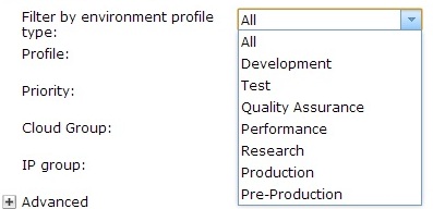
- Click OK to create the profile. When the information is processed, the new profile is added to the list on the left.
- Complete the configuration in the environmental profile details, so that the environment profile can be ready to use.
- Virtual machine name format
- Use the following predefined variables:
- ${hostname}
- Replaced with the host name of the virtual machine, for example: My${hostname}VM.
Underscores are not valid characters in the virtual machine host name.
- ${vs-name}
- Replaced with the name of the virtual system instance, for example: My${vs-name}VM. This variable cannot be used alone in the Virtual machine name format field. The ${vs-name} variable must be used with one of the other formatting variables. Otherwise, if a cluster pattern is being deployed, all virtual machines have the same name and the deployment fails.
- ${x-counter}
- Replaced with a counter of x digits, for example: MyVM${3-counter}. The x in this example represents the number of digits for the counter. If the value of x is 2, then it is represented as 02. This value could be 01, 02 or 03, for example.
- IP addresses provided by
- Choose whether you want the IP address for a virtual machine to be provided by the system or specified when the pattern is being deployed:
- IP Groups
- If the system is to provide the IP address for a virtual machine, you must specify only the cloud group and IP group. Specify these options when you define the parts to deploy the pattern. The system provides the IP address information.
- Pattern deployer
- To provide the IP address for a virtual machine at deployment, you must also specify the following information for each part:
- Cloud group
- IP group
- Host name
- IP address
If you choose this option, you cannot specify an IP address that is contained within the IP groups that are defined in the system at deployment.
Restriction: If the IP addresses provided by field in the environment profile is set to the value Pattern Deployer, then the environment profile cannot be used for Image Construction and Composition Tool or the IBM Image Construction and Composition virtual application pattern.
- Deployment priority
- Select from the following
- Platinum - High(16) Medium(8) Low(4)
- Golden - High(12) Medium(6) Low(3)
- Silver - High(8) Medium(4) Low(2)
- Bronze - High(4) Medium(2) Low(1)
- Deploy to cloud groups
- Click this field to select available cloud groups that are configured
and ready for use. Only valid cloud groups that are configured with the correct hypervisor type are available. When you select a cloud group the following information for the IP groups in that cloud group is provided:
- In use
- Click this check box to use the IP group in the environment profile.
- Name
- Name of the IP group in the cloud that you selected.
- Alias
- You can specify an alias name for the IP group for use in the environment profile. The default setting is the actual name of the IP group.
- Subnet address
- Subnet address of the IP group.
- Gateway
- Specifies the gateway address of the IP group.
- Netmask
- Netmask address of the IP group.
- Environment limits
- This section describes the limits of the virtual CPU, virtual memory, storage and product licenses. Data includes number of processors used and reserved, total megabytes of virtual memory used and reserved, total megabytes of storage in use and reserved, and the product license limits.
- In the product table, you can set the license limit for each product by clicking the up or down arrow in the License limit column. The license limit is ignored when the value of the License limit field is 0. Any other value in the License limit field indicates enforcement of the limit to that value. The License limit field will override the Ignore setting on the License awareness page.
- Access granted to...
- Click this field to specify access to this environment profile for other users or groups of users. Select users, or groups of users, to make the environment profile readable or writable to this group.
Initially, this field is set to the role of the owner of the environment profile.
By default, the Add more menu contains the Everyone User group. When a user or group is added, click the link beside the entry to toggle between the following access levels:
- Read
- Write
- All
Click the link name of the user or group to show information about that user. You can also click the remove link to remove access for a user or user group.
- Comments
- Click Add Comment to add information that is attached to this environment profile.
What to do next
If there are no errors and all the resources the environment profile contains are operational, you can deploy it to the cloud or clouds you specified.
Clone environment profiles
Cloning an environment profile provides a starting point for configuring a new environment profile as you can reuse some of the existing configuration. Select an environment profile that most closely meets your needs, with the hypervisor type you want to use. The hypervisor type cannot be changed when you clone an environment profile.
If the profile is to deploy in a cloud other than the one specified in the profile you are cloning, have a cloud group configured and ready. All hypervisors must be configured and available in a cloud to create an environment profile that is ready to be deployed.
You can use the workload console, the command line interface, or the REST API to complete this task.
- Click...
-
Cloud > Environment Profiles
- Click the profile and click the Clone icon on the toolbar.
- Provide the following information about the new environment profile:
- Name
- Enter a new unique name for the environment profile.
- Description
- Optionally, enter a detailed description to identify and differentiate the environment profile.
- Click OK. When the information is processed, the details about the new profile are shown in the right pane.
- Edit the environment profile.
Modify environment profiles
Modify environment profiles to suit the changing needs of your environment. To deploy a profile in a different cloud than the one specified in the profile, ensure that any new cloud groups are configured. All hypervisors must be configured and available in a cloud to add the cloud group to an environment profile. You can use environment profiles to track CPU, memory, storage, license consumption and stop deployments at a particular size. If you have administrative permission, you can also change the high water marks. Each profile indicates the number of cloud resources used by IBM PureApplication System W1500.
You can use the workload console, the command line interface, or the REST API to complete this task.
- Click...
-
Cloud > Environment Profiles
- Select the environment profile to edit.
- Optional: Check the Access granted to field to see if you have access to edit the profile. If you do not have access, contact the owner to ask for access.
- Edit the following information:
- Add or change the description of the environment profile in the Description field.
- In the Environment field, select an environment for your profile to run:
- All
- Development
- Test
- Quality Assurance
- Performance
- Research
- Production
- Pre-Production
- In the Virtual machine name format field, specify or change the format of the virtual machine name. For example, d_${hostname}.
- In the IP addresses provided by field, select one of the following options to specify how the IP addresses are provided:
- Pattern deployer
- If you choose to provide the IP address for a virtual machine at deployment, then you must also specify the cloud group, IP group, host name, and IP address for each part.
If you choose this option, then the person who deploys the pattern cannot specify an IP address that is contained within the IP groups that are defined in the system.
- IP Groups
- If the system provides the IP address for a virtual machine, you must specify only the cloud group and IP group for the pattern parts. The system provides the IP address information
- Add, remove, or change the alias name for the cloud in which the environment profile is to run.
- Add
- To add a cloud group, click the entry field under the Deploy to cloud groups label and select the cloud group to add. Only valid cloud groups that are configured with the correct hypervisor type are shown.
- Remove
- Click the Remove link beside any listed cloud groups to remove them from the environment profile.
- Change alias name
- In the Alias field, change the name of the cloud. This name is shown at deployment.
- Add, remove, or rename IP groups. Select or clear the In use box to indicate the IP groups in each cloud group to be used. You can also change the name of the IP group, as it is shown at deployment, in the Alias field.
- Grant or remove access to the environment profile to users. Use the Access granted to field to add, remove, or change user or user group access to this environment profile.
If the hypervisors and resources for the cloud group specified are available, the environment profile can be deployed to the cloud.
Delete environment profiles
Use the workload console to delete environment profiles fromIBM PureApplication System W1500.
You must be assigned one of the following roles...
- Workload resources administration
...with permission to...
-
Manage workload resources (Full permission)
- Create new environment profiles
You can use the workload console, the command line interface, or the REST API to complete this task.
- Click...
-
Cloud > Environment Profiles
The Environmental Profiles panel displays with a list of profiles on the left.
- Click the environmental profile to delete.
- Click the Delete icon. Click OK to confirm to delete the environment profile.
Manage instances
You can manage instances in two ways. Use the menu to manage individual types of instances deployed in your cloud, including databases, virtual applications, virtual systems, and shared services. You can also use the following procedure to manage all instances from one pane.
-
Instances | All Instances
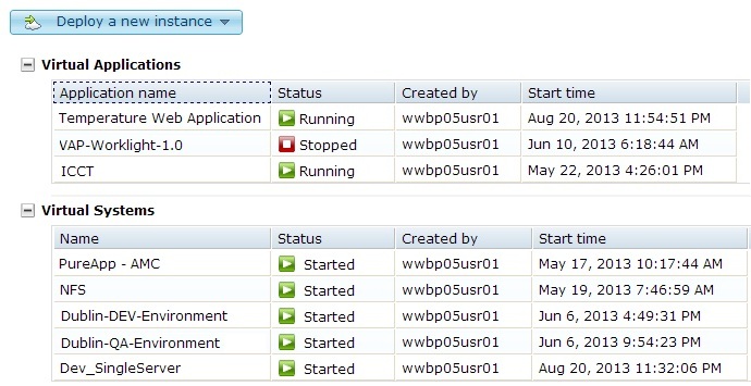
When you expand an instance section, details display, including instance name, status, owner, and instance start time.

Instance types include....
- virtual application
- virtual system
- shared service
- database
Deploy virtual applications from the Instances pane
After you create a virtual application, you can provision and deploy it to the cloud. You must be assigned one of the following roles
- Workload resources administration
...with permission to...
-
Manage workload resources (Full permission)
- Workload resources administration
...with permission to...
-
View all workload resources (Read-only)
- Create new patterns
- Create new catalog content
- Create new environment profiles
- IBM License Metric Tool (ILMT) user
Deploy virtual applications...
- Go to...
-
Instances | Virtual Applications | New icon

- Select pattern type

- Select virtual application pattern

- Specify the settings for the deployment.
- IPv4 or IPv6
- Filter by environment profile type
- Profile
- Priority
- Cloud group
- IP group

- Expand the Advanced section to configure the advanced settings.
- The SSH key provides access to the virtual machines in the cloud group for troubleshooting and maintenance purposes.
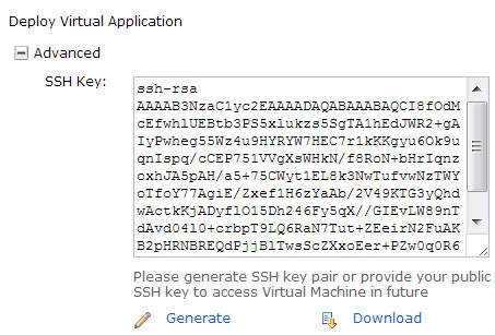
Use one of the following options to set the public key:
- To generate a key automatically, click Generate.
Click Download to save the private key file to a secure location. The default name is id_rsa.txt. The system does not keep a copy of the private key. If you do not download the private key, you cannot access the virtual machine, unless you generate a new key pair. You can also copy and paste the public key into a text file to save the key. Then, you can reuse the same key pair for another deployment. When you have the private key, make sure that it has the correct permissions (chmod 0400 id_rsa.txt). By default, the SSH client does not use a private key file that provides open permission for all users.
- To use an existing SSH public key, open the public key file in a text editor and copy and paste it into the SSH Key field.
Do not use cat, less, or more to copy and paste from a command shell. The copy and paste operation adds spaces to the key that prevent you from accessing the virtual machine.
- To generate a key automatically, click Generate.
- The SSH key provides access to the virtual machines in the cloud group for troubleshooting and maintenance purposes.
- Click OK.
Administer virtual application instances
Each deployment of a virtual application represents a running virtual application instance on the cloud environment. You can view and monitor deployed virtual application instances from the workload console. Deploy a virtual application to the cloud environment. You must be assigned one of the following roles
- Workload resources administration
...with permission to...
-
Manage workload resources (Full permission)
- Workload resources administration
...with permission to...
-
View all workload resources (Read-only)
- Create new patterns
- Create new catalog content
- Create new environment profiles
- IBM License Metric Tool (ILMT) user
To administer virtual application instances...
- Open Virtual Applications
-
Instances | Virtual Applications

Use these options to filter the list of virtual application instances:
Search Enter the name of a virtual application instance in this field to search for it. Pattern type Select a pattern type from the list to display only virtual application instances based on that pattern type. Sort Click to sort the list of virtual application instances by application name or by status. - Select the virtual application instance to administer.
- Toolbar options
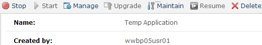
- Refresh
- Refresh the status of the virtual application instances and updates the fields on the Virtual Application Instances pane.
- Stop
- Stop a started virtual application instance. Associated cloud resources are not released.
- Start
- Start a stopped virtual application instance.
- Manage
- Virtual Application Console displays.
- Click Monitoring to view advanced monitoring details and operations for the virtual machines or middleware by selecting the corresponding submenu.

- Click Logging to view and download the logs.

- Click Operations to view the operations for the instance.

Use this tab to update operations that are associated with the instance. The following list shows some of the operations that might be available: Some of the following operations might not be available for all virtual application instances, and some virtual application instances might have more operations.
AGENT Enter a trace string in the Trace string applied to the agent field. Enter the trace file name, such as trace.log, in the Trace File Name field. Enter the maximum file size in the Trace Max File Size field. Enter the maximum number of trace files in the Trace Max File Size field. Click the Append to trace file check box to append the trace file. Click Submit. 
AUTOSCALING To pause or resume auto scaling tasks, select or clear the Pause check box and click Submit. MAINTENANCE Use this tab to install maintenance fixes. 
MONITORING To connect or disconnect the operating system and workload monitoring agents to the monitoring service defined in the service registry, select or clear the Connect check box. Click Submit. To start or stop monitoring of the WebSphere Message Broker, click Submit. SSH To add or update the virtual machine SSH public key, type the public key in the Public Key field and click Submit. To remove the virtual machine SSH public keys, click Submit. 
- Click Links to view the endpoint links for the instance.

- Click Main Console to go back to the main workload console.
- Click Monitoring to view advanced monitoring details and operations for the virtual machines or middleware by selecting the corresponding submenu.
- Maintain
- Click Maintain to put the virtual application instance in maintenance mode. Use maintenance mode when you apply fixes or other upgrades to virtual applications. When a virtual application instance is in maintenance mode, you can stop and start the individual role virtual machines within the application without activating the recovery or scaling policies. After you are finished with the instance in maintenance mode, click Resume to remove the instance from maintenance mode.
When an instance is running in maintenance mode, it runs as normal; however some accommodations are made so that the instance can be maintained while it is running. An instance that is in maintenance mode has several features that are suppressed such as auto scaling and auto recovery, and you can manually start and stop virtual machines. When a virtual application instance is running in maintenance mode, click Stop to initiate scripts that ensure that middleware running on the virtual machine can be stopped safely.
- Delete
- Removes the virtual application instance from the cloud. Associated cloud resources are released.
Virtual application instance details

- Name
- Name of the virtual application instance.
- Created by
- User who deployed the virtual application instance.
- Access granted to
- User who first deployed the virtual application instance. As owner, automatically granted all access to the virtual image. Other users must be granted access. Only the original owner can perform management tasks. Other users, even with all access, cannot perform manage individual virtual machines.
- ID
- Shows the ID associated with the deployment.
- Status
- Status and health status of the deployment. Possible status values for a deployed virtual application...
Status Deployment description Virtual machine description LAUNCHING Virtual application is being deployed. VM is being provisioned on the infrastructure cloud. INSTALLING Not applicable Components of the virtual application are being provisioned on the VM. RUNNING Resources are being provisioned on the infrastructure cloud. Components of the virtual application are running on the VM and can be accessed. TERMINATING Virtual application instance resources are being deleted. VM is being deleted Resources are released. TERMINATED Virtual application instance resources are deleted. History files are retained. VM is deleted and resources were released. STOPPING Virtual application instance is stopping. VM is being stopped. STOPPED Virtual application instance is stopped. The virtual application can be made available again by starting the instance. VM is stopped and it can be restarted. FAILED The deployment process could not be started because of either the application configuration or a failure that is occurring in the infrastructure cloud. VM did not start successfully. ERROR An error occurred during deployment. Check the logs and determine the cause of the error before you redeploy the virtual application. VM status. NOT_READY Virtual application instance is in maintenance mode. The NOT_READY status does not apply to VM. - Use Environment profile...
- Shows the environment profile, if any, that was used to deploy the virtual application instance by providing a link to that profile. Click the link to display details for that environment profile.
- Priority
- Priority for the deployment (such as Low, Medium, or High).
- In cloud group
- Cloud group for the virtual application instance.
- Referenced shared services
- Link to shared services referenced by the virtual application instance
- Pattern type
- Pattern type the virtual application pattern was built from.
- From pattern
- Link to virtual application pattern details.
- Middleware perspective
-
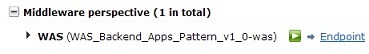
The Endpoint link displays endpoint information. More than one endpoint is supported for a DB2 deployment; for example, one for the application developer, and one for the database administrator.
- Virtual machine perspective
-

Details for the virtual machines in the virtual application instance. VM Status shows the status of the virtual machine. Click the Logs link to view logs for the virtual machine. Middleware Status shows the status of the middleware that you are viewing the details for.
- History
- Show the activity history for the virtual application instance.
ssh to virtual machine
To access the virtual machine after deployment...
- ssh -i id_rsa.txt virtuser@<workload_ip>
To enable password-less logon to the virtual machine...
- scp -i id_rsa.txt myfiles.txt virtuser@<workload_ip>
To run a command with root access:
- sudo /sbin/ifconfig
To gain root access:
- sudo su - root
View and monitor statistics for your deployed virtual machines and download and view the log files.
Apply a fix to virtual application base image or plug-in
After a virtual application is deployed, you can apply fixes from the catalog to either the base image or a lifecycle script in the virtual application instance. Fixes must be packaged and exist in the catalog before you can apply them. You must be assigned one of the following roles
- Workload resources administration
...with permission to...
-
Manage workload resources (Full permission)
- Workload resources administration
...with permission to...
-
View all workload resources (Read-only)
- Create new patterns
- Create new catalog content
- Create new environment profiles
- IBM License Metric Tool (ILMT) user
There are two types of fixes that you can apply to a virtual application instance from the Virtual Application Console:
- An update to the operating base image by applying an emergency fix to the virtual image.
- An update to a role used by a virtual application instance.
To apply fixes...
- From the workload console...
-
Instances | Virtual Applications | virtual_application_instance | Manage | Operations | MAINTENANCE
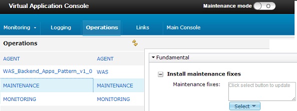
The Maintenance fixes field lists any maintenance fixes that are already installed.
- Click Select and choose the fixes to apply.
- If there are dependencies between fixes to install, deploy each fix separately instead of submitting them at the same time to avoid conflicts.
- Fixes for middleware are displayed here; however, you must not attempt to deploy from here.
- To install a middleware fix, use the update feature available with the middleware role.
- Click Submit.
The status of the installation is displayed in the Operation Execution Result section. You can also check more detailed information in logs for the MAINTENANCE role.
Secure web applications with SSL
The security of a virtual application instance based on IBM Web Application Pattern can be managed with SSL certificates. You can manage personal and application SSL certificates in WebSphere Application Server keystore and truststore for secure inbound authentication and communication. To ensure SSL communication, servers require a personal certificate that is either self-signed, chained or signed by an external certificate authority (CA). The SSL functionality is a simplified security layer on top of, and subset of, what is provided by WebSphere Application Server.
Renew the default certificate
The system supports the use of one certificate per application deployment. By default, your deployed application has a uniquely generated certificate that is signed by the internal WebSphere root signer certificate. The certificate is valid for one year, but can be renewed at any time. This operation is only available for the default application certificate. If you replaced the default application certificate with a CA-signed certificate, the operation fails.
-
Instances | Virtual Applications | virtual_application_instance | Manage | Operation | WAS | Security | Renew the WebSphere Application Server application SSL certificate | Confirm

When the operation displays as successful, the validity of the certificate is extended. If your deployment has multiple WebSphere Application Server nodes, you might have to wait a short time for the updated certificate to propagate to all of the application servers.
Request external signed certificate
You can replace the default certificate with a certificate signed by an external certificate authority.
- From the Workload Console...
-
Instances | Virtual Applications | virtual_application_instance Manage | Operation | WAS | Security | Configure a CA-signed certificate
- Create a signer request.
First create a personal certificate request. Expand Create CA signer request in the deployment operations pane and complete the fields.

The common name (CN) matches the domain name used for the application. Click Submit. When the operation is complete, the status shows as successful in the Operation Execution Results pane. A link is available in the Return Value column to download the newly generated signer request file. Provide this file to the CA for signing.
PureApplication supports only one pending certificate signer request. If a new request is created before the CA-signed certificate corresponding to a previous request is accepted, that certificate is no longer accepted.
- Import a CA-signed certificate
Expand Upload a CA-signer request. The signed certificate must correspond to the last signer request created for the application deployment in question. After the certificate is imported, it replaces the previously configured application certificate, whether that is the default WebSphere signed certificate or a previously imported CA-signed certificate. To import, click Browse to locate the certificate file. The certificate file can be in base64-encoded PEM or binary-encoded DER format. A progress bar shows that the file is uploading. When the upload completes, click Submit to complete the operation. Success is indicated in the Operation Execution Results pane.
Import and export a truststore certificate
Perform these steps to import a WebSphere Application Server truststore certificate. There is no limitation on the number of external signer certificates that you can import and store in the truststore. For deployed applications to securely connect to external services over SSL, the appropriate signer (public) certificates must be in the WebSphere Application Server truststore.
- Click...
-
Instances | Virtual Applications virtual application instance | Manage | Operation tab | WAS | Security | Import WebSphere Application Server truststore certificate
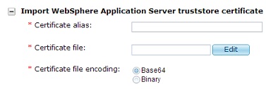
- Specify the certification information:
- Certificate alias
- Enter the name of the certificate alias. Record the alias that you specify. The Virtual Application Console does not provide a list of previously imported certificates.
- Certificate file
- Click Edit to specify the certificate file. You can choose a local file on the Local tab or specify the HTTP or HTTPS URL for a file that is stored on another computer on the HTTP/HTTPS tab.
- Certificate file encoding
- Select the encoding format of the certificate.
- Click Submit.
- If you want to later remove a previously imported signer certificate from the truststore, expand Remove WebSphere Application Server truststore certificate. Specify the alias of the certificate and then click Submit.
- You can also extract and export the signer part of the current application SSL certificate or the WebSphere root signer certificate from the deployment operations screen. Expand Export certificate and select a certificate to export from the menu (Application certificate or WebSphere Application Server root signer certificate), and click Submit.

You can choose the base64-encoded PEM or binary-enconded DER certificate format. When the certificate is ready, the operation status displays as successful in the Operation Execution Results pane. You can download the file by using the link in the Return Value column.
Configure SSH key-based access
You can add Secure Shell (SSH) key-based access to a virtual machine during virtual application pattern deployment, or add it to a virtual application instance after deployment. This type of security provides better protection than password-based access.
To access deployed virtual machines for troubleshooting and maintenance purposes, set up SSH key-based access with an RSA key pair. The key has user ID "virtuser". You can either provide your own externally generated public key or use a key pair that is generated by the system.
After you generate the key pair, you can install the public key during virtual application pattern deployment and give the private key to users who are allowed to access the virtual machines for debugging and maintenance. Store a copy of your SSH private key file in a secure location. After you generate the public and private keys, you can upload the public key to virtual machines in an existing deployed virtual application instance.
Generate an SSH key
If you do not have an existing RSA key pair, you can generate one from the user interface or you can use a third-party application to generate a key pair. Use these instructions to use the system to generate an SSH key.
- From the Workload Console...
- Click...
-
Patterns | Virtual Applications | virtual application pattern | Deploy icon
- In the Deploy Virtual Application dialog box, expand the Advanced section to add the SSH protocol key and click Generate...

The SSH public key is automatically populated in the SSH Key field. You can use an existing public key or generate a new key.
- Copy and save the generated public key from the SSH Key field.
- To save the private key file.
-
Download | Save
The default name is id_rsa. On Windows, the file might be saved as id_rsa.txt. The PureApplication system does not keep a copy of the private key. If you do not download the private key, you cannot gain access to the virtual machine, unless you configure a new public key. Save the public key and id_rsa private key file in a secure location.
- To continue with the deployment and upload the generated public key, specify the remaining required information and click OK. Otherwise, cancel the deployment.
The SSH key pair is generated and can now be used to set up access to virtual machines in multiple deployments. When you use the same key pair for multiple deployments, users who maintain or troubleshoot VMs in your environment do not need to reconfigure their SSH client with a different private key each time they access a particular virtual application instance. The generated id_rsa private key file is in OpenSSH format and can be used with OpenSSH and is compatible with SSH clients. To use the key with other clients, the key might need to be converted to a different format. If this conversion cannot be done, you can generate a key pair separately. You can also generate an SSH key when you configure shared services.
To regenerate an SSH key...
- sshkey reset
To verify the complexity of the SSH key...
- sshkey verify
Upload the public key
Install your public key to any virtual machines that you wish to connect to.
- For new virtual application patterns, you can upload the public key during deployment by copying and pasting the public key into the SSH Key section of the Deploy Virtual Application dialog box.
Do not copy the key from the console output of the UNIX commands cat, less, or more, which can introduce line breaks into the key that might render it invalid.
- If SSH key-based access is not configured for an existing virtual application instance, you can upload a new public key. You can also replace an existing public key with a new one if you generated a different SSH key pair to access virtual machines in the virtual application instance.
When you troubleshoot or perform maintenance on a particular virtual machine, you can connect to it using SSH. There are several ways to make an SSH connection to a virtual machine.
Upload SSH keys to a virtual application instance
To debug and adjust the scripts, connect to the virtual machines using SSH. If SSH is not already configured for the virtual application instance, you can upload the key to the deployed instance.
- From the Workload Console
-
Instances | Virtual Applications | virtual application pattern | Manage | Operation | SSH | Add or update virtual machine SSH public key

- To upload an SSH public key, copy and paste your public SSH key in the Public Key field and click Submit.
If an existing public key was previously entered in the Public Key field, the old public key is replaced. Do not copy the key from the console output of the UNIX command "more". By doing so you might introduce line breaks into the key that render it invalid.
- To remove existing SSH public keys, click Submit in the Remove virtual machine SSH public keys section.
Configure LTPA keys
LTPA is an authentication technology used in the web application deployed into the cloud infrastructure. You can manage LTPA keys for a deployed virtual application that is based on IBM Web Application Pattern. You can regenerate, import, and export LTPA keys.
- Click...
-
Instances | Virtual Applications | WAS virtual application instance | Manage | Operation | WebSphere Application Server application | Regenerate LTPA keys | Submit

When the operation status is displayed as successful in the Operation Execution Results pane, the LTPA keys are regenerated.
- To import LTPA keys, expand Import LTPA keys in the Deployment operations pane.

Click Browse to locate the LTPA keys and click Submit. When the operation status is displayed as successful in the Operation Execution Results pane, the LTPA key is imported.
- To export LTPA keys, expand Export LTPA keys in the Deployment operations pane and click Submit.
When the operation status displayed as successful in the Operation Execution Results pane, the LTPA key is exported and can be downloaded.
Troubleshoot virtual applications
To troubleshoot virtual applications, enable tracing for the workload agent process. By default, only information level messages are recorded. You can enable all log levels. You can configure the workload agent plug-in of the agent process for all new virtual application deployments, or configure the agent in an existing virtual application instance
Tracing for new deployments
Go to...
-
Cloud | System Plug-ins | Foundation Pattern Type | agent plug-in | Configure
...and specify the appropriate settings...
- Trace string applied to the agent
- Default is *=info=enabled. To enable all traces, set....
-
*=info=enabled:
com.ibm.maestro.common.*=all=enabled:
com.ibm.maestro.agent.*=all=enabled:
com.ibm.maestro.profile.*=all=enabled:
com.ibm.maestro.security.*=all=enabled:
com.ibm.purescale.profile.*=all=enabled:
com.ibm.purescale.security.*=all=enabled:osgi=all=enabled:
com.ibm.ws.bbson.ConfigOracle=all=enabled:
com.ibm.ws.bbson.api.connectivity.local.*=all=enabled:
com.ibm.ws.bbson.api.traffic.local.*=all=enabled:
com.ibm.ws.bbson.api.connectivity.remote.*=all=enabled:
com.ibm.ws.bbson.api.traffic.remote.*=all=enabled:
com.ibm.ws.bbson.BBFactoryImpl=all=enabled:
com.ibm.maestro.elbservice.management.*=all=enabled:
com.ibm.maestro.sharedservice.genericREST.resources.*=all=enabledEnter the trace string as one continuous string without spaces or line breaks.
- Trace File Name
- Default is trace.log.
- Trace Max File Size
- The maximum trace log file size in MB. The default size is 40 MB. When a log file reaches the specified maximum size, a new log file is created. The file name for the new trace log includes a numeric suffix, and the suffix increments for each new file. For example, trace.log.1, trace.log.2, trace.log.3.
- Trace Max File Number
- The maximum number of trace log files that can be created. The default is 20 files. Each trace log file has a numeric suffix. For example, trace.log.0, trace.log.1, trace.log.2, trace.log.3.
If the maximum number of files is reached, a new sequentially numbered trace log file is created and the oldest trace log file is deleted. For example, if the maximum value is 20, only 20 trace log files are saved at a time. The file trace.log.20 is created when trace.log.19 reaches the maximum file size and trace.log.0 is deleted.
- Append to trace file
- If this option is selected, data is appended to the most recent existing trace log file each time a new set of information is recorded to the trace log until the maximum file size is reached. If this option is not selected, a new trace log file is created each time a new set of information is required in the trace log, even if the maximum file size of the most recent log file is not reached.
After you deploy a new virtual application, to view trace logs...
-
Instances | Virtual Applications | virtual application instance | Manage | Logging tab
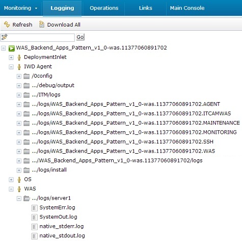
Logs are organized by virtual machine name, and each name contains the name of the roles that are associated with the virtual machine. A role within a virtual application refers to the software that is installed and configured. Expand the IWD Agent role and then expand the entry with the /logs subdirectory. For example, if the virtual machine name is Web_Application-was.11332975226124, expand the entry...
-
Web_Application-was.11332975226124/logs

The log file with the file name that you configured is listed under the /logs directory. Select the trace log to view the contents in the detail pane.
When you no longer need the trace logs for troubleshooting or debugging, reset the trace string. Repeat the preceding steps and set the trace string to *=info=enabled.
Configure tracing for an existing virtual application instance
- Click...
-
Instances | Virtual Applications | virtual application instance | Manage | Operation | Agent role
- Select Update agent trace settings

- Trace string applied to the agent
- Default is *=info=enabled.
To enable all traces...
- *=info=enabled
com.ibm.maestro.common.*=all=enabled:
com.ibm.maestro.agent.*=all=enabled:
com.ibm.maestro.profile.*=all=enabled:
com.ibm.maestro.security.*=all=enabled:
com.ibm.purescale.profile.*=all=enabled:
com.ibm.purescale.security.*=all=enabled:osgi=all=enabled:
com.ibm.ws.bbson.ConfigOracle=all=enabled:
com.ibm.ws.bbson.api.connectivity.local.*=all=enabled:
com.ibm.ws.bbson.api.traffic.local.*=all=enabled:
com.ibm.ws.bbson.api.connectivity.remote.*=all=enabled:
com.ibm.ws.bbson.api.traffic.remote.*=all=enabled:
com.ibm.ws.bbson.BBFactoryImpl=all=enabled:
com.ibm.maestro.elbservice.management.*=all=enabled:
com.ibm.maestro.sharedservice.genericREST.resources. *=all=enabledEnter the trace string as one continuous string without spaces or line breaks.
- Trace File Name
- The name for the trace file. The default file name is trace.log.
- Trace Max File Size
- The maximum trace log file size in MB. The default size is 40 MB. When a log file reaches the specified maximum size, a new log file is created. The file name for the new trace log includes a numeric suffix, and the suffix increments for each new file. For example, trace.log.1, trace.log.2, trace.log.3.
- Trace Max File Number
- The maximum number of trace log files that can be created. The default is 20 files. Each trace log file has a numeric suffix. For example, trace.log.0, trace.log.1, trace.log.2, trace.log.3. If the maximum number of files is reached, a new sequentially numbered trace log file is created and the oldest trace log file is deleted. For example, if the maximum value is 20, only 20 trace log files are saved at a time. The file trace.log.20 is created when trace.log.19 reaches the maximum file size and trace.log.0 is deleted.
- Append to trace file
- If this option is selected, data is appended to the most recent existing trace log file each time a new set of information is recorded to the trace log until the maximum file size is reached. If this option is not selected, a new trace log file is created each time a new set of information is required in the trace log, even if the maximum file size of the most recent log file is not reached.
- Click Submit.
Tracing is configured for all the workload agents in the deployment.
- To view the trace logs for the agent, click the Logging tab.
Logs are organized by virtual machine name, and each name contains the name of the roles that are associated with the virtual machine. A role within a virtual application refers to the software that is installed and configured.
- Expand the IWD Agent role and then expand the entry with the /logs subdirectory.
The log file with the file name that you configured is listed under the /logs directory. Select the trace log to view the contents in the detail pane.
*=info=enabled
Delete virtual machines and reclaim IP addresses
A virtual machine that is part of a virtual application instance can go into the Stopped state. In the Stopped state, the IP address that is allocated to that virtual machine remains in use and cannot be allocated to other virtual machines. If you no longer require the virtual machine, you can delete it.
You must be assigned the role...
...with permission to...
-
Manage all cloud groups (Full permission)
When you delete a virtual machine, its IP address is put back into the pool of available IP addresses. The recovery rules take effect, which can result in the IP address immediately being allocated to a new running virtual machine. You can view currently allocated IP addresses by virtual application instance, by IP group, or by hypervisor. From either the system console or the workload console, select the appropriate option:
- Virtual application instance
-
Instances | Virtual Applications | instance | Virtual Machine
- IP group
-
Cloud | IP Groups | IP group | Virtual Machine
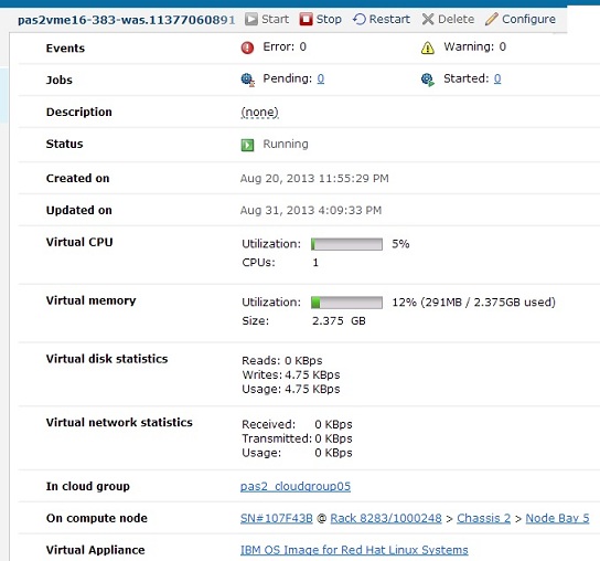
When a virtual machine is stopped, the IP address is not released. On the IP Groups page, the IP address for the stopped virtual machine is displayed as Active. This status remains true until the virtual machine is deleted.
-
Cloud | Virtual Machines | virtual machine | Delete
Delete a virtual application instance
You delete a virtual application instance when it is no longer needed.
-
Instances | Virtual Applications | instance | Delete
Monitor virtual application instances
Have the Workload resources administration with full permissions to complete this task. Before starting, deploy the shared services....
- System Monitoring
- System Monitoring for WebSphere Application Server
The System Monitoring shared service provides the monitoring infrastructure that allows monitoring agents to collect performance and availability information. Monitoring services for middleware are separate shared services deployed in addition to the base System Monitoring service. You can deploy the System Monitoring for WebSphere Application Server service in a cloud group to collect performance and availability data from applications that are running on virtual applications within that cloud group. The shared service uses a monitoring agent and data collector to collect the data from these applications. If the System Monitoring for WebSphere Application Server service is deployed, monitoring for application servers is installed on all virtual machines with WebSphere Application Server components. The System Monitoring for HTTP Servers service is not currently supported for use with virtual applications.
To monitor...
-
Instances | Virtual Applications | instance | Manage | Monitoring

View virtual application instance logs
You can view logs of virtual application instances. All of the virtual machines in the deployed virtual application must be started before you view the logs.
-
Instances | Virtual Applications | instance | Manage | Logging

Logs are organized by virtual machine name, and each name contains the name of the role that is associated with the virtual machine. A role within a virtual application refers to the middleware that is installed and configured. For example, a virtual machine named application-was.11332975226124 contains was. This virtual machine has IBM WebSphere Application Server installed and configured.
Under each virtual machine in the list, logs are organized into sections, such as operating system log, logs for the type of middleware that is installed, pattern type plug-in log, and agent log. If you specified more log files or directories to monitor in the Logging Policy, these logs also display in this list.
At the top of the list of virtual machines, you can specify a string to filter what files are displayed in the log viewer and then click Go. The filter can be prefixed by a tag that specifies one or more elements of the logs to be examined.
| Tag | Description | Example |
|---|---|---|
| role: | The role name. | role:DB2 |
| dir: | Absolute path of the directory that contains the log. The filter searches the entire path for the specified file, but does not search within the log file name. | dir:var |
| vm: | Virtual machine name. | vm:application |
| file: | Log file name. | file:trace |
The following usage rules apply to filters:
- If a tag is not included in a search string, the file: tag is assumed.
- Tag names are case-sensitive, but the filter string after the tag is not case-sensitive. For example, the string role:WAS matches a role name WAS and a role named was, but the string ROLE:was does not match anything because ROLE is not recognized as a valid tag.
- You can apply multiple filters. For example, role:DB2,trace filters for logs with a name that contains trace, and that belongs to a role with a name that contains DB2.
To search the text of a log, click the log file name in the list and then click Search on the toolbar and specify the search criteria. You can use the Previous and Next commands on the toolbar to search for the next or previous occurrence of the last specified search string.
The following options are available to save logs:
- Download all log files
- When no filter is applied to the list of logs, or when the filter input box is cleared, you can click Download All to save an archived, compressed file, which contains all the logs on the virtual machine. If multiple virtual machines are displayed in the log viewer, a separate archive file is returned for each virtual machine.
- Download all files in a filtered list of logs
- When you enter a string into the filter box to select a subset of logs, you can click Download Filtered to download all of the files that are displayed in the filtered list as a single archive file.
- Download an individual log
- To save a specific log file, hover over the name of a log file in the list of logs and click the Download log icon that displays next to the name of the file. Alternatively, click the log file name and click the Save icon on the toolbar.
Manage virtual system instances
A virtual system instance is the virtual environment that is being managed by the PureApplication System. To create a virtual system instance, deploy a pattern into the cloud.
You must specifically be granted access to the virtual system instances or be assigned the Administrator role with full permissions to perform these steps.
Virtual system instances are using created patterns composed of parts provided in the virtual images. The pattern is deployed to hypervisors based on a component of PureApplication System called placement. The placement component decides which hypervisors to use when deploying virtual machines or extending existing virtual system instances by adding virtual machines. It uses an algorithm that considers...
- The properties of the physical machines
- Existing virtual system instances on the hypervisors
- Virtual machines on the hypervisor not managed by PureApplication System
- Memory, physical CPUs, network addresses, disk space, and disk image sharing on the hypervisor
The placement component is part of the product code and is not configurable.
Besides determining where virtual machines are deployed, the placement component also performs the job of deciding whether to permit a specific virtual system instance deployment. The product licenses can be counted when PureApplication System is configured to enable license tracking. Use this configuration to prevent the number of deployments from exceeding your maximum allowed number of licenses.
The virtual system instances are managed by PureApplication System and can be serviced and accessed through the console. Virtual system instances managed by PureApplication System are dynamic. Virtual machines can be added or removed to allow the virtual systems to scale based on current demand. You can increase the capacity of the virtual machines to scale for increased user demands by creating clones of existing virtual machines. If needed, you can scale down the environment and remove unnecessary virtual machines.
To use the Database Performance Monitor shared service, ensure you have ports available to use on any virtual system instances. Ports must be reserved for any DB2 that are running as virtual application when configuring virtual system instances. This port number is set when a DB2 instance is installed in a virtual system.
Create snapshot images
You can create a snapshot image to store the current state of the virtual system instance. You can later use this snapshot image to partially restore the virtual system instance to the stored state.
You must be granted access to the virtual system instance or have the Workload resources administration with full permissions role to complete this task. Using the snapshot function, you are able to store the state information for each of the virtual machines in the virtual system instance as it is running. You can use this snapshot image to restore these virtual machines in the virtual system instance to their states that existed when the snapshot was taken. You should be aware of the following conditions:
- By restoring the virtual system instance using a snapshot image, the current state of the virtual system instance is lost.
- You can create only one snapshot image for each VM.
- When you create a snapshot image for a virtual system instance that already has a snapshot image stored, the existing snapshot is removed.
- Any VMs that are added to the virtual system instance after the snapshot image is taken are still present after restoring the virtual system instance to its previously stored state.
To take a snapshot image of the current state of the selected virtual system instance
-
Instances | Virtual Systems | virtual system instance | Create

The virtual system instance status becomes Snapshooting until the snapshot image is completed. When the snapshot is successfully created, it is listed under the Create and the Restore buttons.
After completing these steps, you have a snapshot image available to restore the state of the virtual machines in the virtual system instance to their stored state. Any virtual machines that are added after the snapshot image is taken are unaffected by the restore operation.
Restore virtual system instances from a snapshot image
A snapshot image represents a previously captured state of the virtual system. Using this snapshot image, you can restore the state of virtual machines that were present in the virtual system instance to their stored state at the time the snapshot was taken.
You must be granted access to the virtual system instance or have the Workload resources administration with full permissions role to complete this task. Using the snapshot restore function, you can restore the state information for each of the virtual machines in the virtual system instance to their state when the snapshot was taken. When you restore a virtual system instance by using a snapshot image, the current state of the virtual system instance is lost.
Any virtual machines in the virtual system instance that were added after the snapshot image was taken are still present and are unaffected when you restore the virtual system instance to its previous state.
To restore the virtual system instance to its previously captured state.
-
Instances | Virtual Systems | virtual system instance | Restore
The restore process does not take place instantly, and the virtual system instance is not usable while the virtual system instance is being restored. After the virtual system instance is restored, it is automatically stopped and must be restarted manually.
After completing these steps, the states of the virtual machines that were part of the virtual system instance are restored to the same state as when the snapshot image was created. Virtual machines that were added after the snapshot image was taken are still present and are unaffected by this process.
Delete snapshot images
You can delete a snapshot image of a virtual system instance that you no longer require.
You must be granted access to the virtual system instance or have the Workload resources administration with full permissions role to complete this task. After creating a snapshot image for a virtual system instance, you can delete the snapshot when you no longer need it. An existing snapshot image of a virtual system instance is automatically deleted when a new snapshot image is created.
To delete the snapshot image.
-
Instances Virtual Systems | virtual system instance | Delete
The snapshot image is deleted from the system memory.
Start virtual system instances
Virtual system instances managed by the system are not always running and in the Started state. When a virtual system instance is in either the Stopped state or the Stored state, you can restart the virtual system instance to redeploy the virtual system instance into the cloud.
You must be granted access to the virtual system instance or have the Workload resources administration with full permissions to complete this task.
These steps are only intended for starting a virtual system instance that is in the stopped state or the stored state. To create a virtual system instance, deploy a pattern into the cloud.
When a virtual system instance is stopped, the cloud resources are not released and the virtual system instance remains managed by the system.
The virtual system instance still has an impact on placement decisions though it is not actively running. The resources assigned to this virtual system instance are maintained to ensure that resources are available when the virtual system instance is restarted.
If the virtual system instance has been stored, then other virtual system instances might have consumed the memory required to restart the virtual system instance. If this scenario occurs, then you can stop and then store other virtual system instances to release sufficient memory to ensure the stored virtual system instance can be restarted.
To redeploy the virtual system instance into the cloud by restarting the virtual system instance.
-
Instances | Virtual Systems | virtual system instance | Start icon
Deployment does not happen instantly. The deployment time depends on the virtual system instance size and the system activity. The Start icon is displayed while the deployment process is in progress or all the virtual machines in a cluster have not yet started. When the state of the virtual system instance is "The virtual system has been deployed and is ready to use", then the virtual system instance is running in the cloud and available for use. The Failed icon displays if the virtual system instance does not start successfully.
If the start operation completed successfully, the virtual system instance is ready to be used.
Access virtual machines in virtual system instances
Each virtual system instance consists of a set of virtual machines that represent a physical node in an application server environment. You can access and view details about the individual virtual machines from the virtual system instance.
You must be granted access to the virtual system instance or have the Workload resources administration with full permissions to complete this task. You can access any of the virtual machines that are contained by the virtual system instances.
- View the list of virtual machines in the virtual system instance.
-
Instances | Virtual Systems | instance | Virtual machines

- Expand the details for your selected virtual machine by clicking the Expand icon next to the virtual machine name.
The number of virtual machines that exist for the virtual system instance is dependent on the pattern that was deployed to create it.
- To access the virtual machine, use one of the following steps:
- Click Login under the SSH column to open a new browser window and access the virtual machine by using SSH.
- Click WebSphere under the Consoles section to access the WebSphere Application Server administrative console on the virtual machine.

Your virtual machine must be accessible from the computer that is accessing the console. If a firewall is preventing the connection on the required port, then the port must be opened for this link to establish a connection.
For a VMware ESX environment, ports 80 and 443 are used to communicate with the hypervisor by using the web services interface. To communicate with the virtual machines by using SSH, port 22 is used.
- Click Login under the SSH column to open a new browser window and access the virtual machine by using SSH.
View virtual machine details
Each virtual system instance consists of a set of virtual machines that represent a physical node in an application server environment. These virtual machines are assigned to and hosted by a hypervisor. You can view the details for each virtual machine.
You must be granted access to the virtual system instance or have the Workload resources administration with full permissions to complete this task.
To view the details about virtual machines for the virtual system instance.
-
Instances | Virtual Systems | instance | Virtual machines
You can view the following details for each virtual machine:
| CPU | Graphically displays the percentage of the virtual CPU power that is currently being used. The number of virtual CPUs available is determined by the pattern used to create the virtual system. The default number of virtual CPUs for a virtual machine is one. | ||||||||
| Memory | Graphically displays the percentage of the memory that is currently being used by the virtual machine. The amount of memory available is determined by the pattern used to create the virtual system instance. The default amount of virtual memory for a virtual machine is 2048 MB. | ||||||||
| SSH | A Login link to log in to the virtual machine by using Secure Shell (SSH). | ||||||||
| Actions | The available actions for a virtual machine. If an action is not available, it is not active. Click the Manage link to display a submenu of actions that you can perform:
|
Expand the details for a virtual machine by clicking the expand icon next to the virtual machine name.
View the virtual machine details.
Stop and store virtual system instances
You can stop and optionally store a virtual system instance without removing it from the system. If you stop a virtual system instance from running, the system still manages its associated resources, and you can redeploy the virtual system instance at a later time.
You must be granted access to the virtual system instance or have the Workload resources administration with full permissions to complete this task.
When you stop a virtual system instance, the system resources are not released. A stopped virtual system instance still affects placement decisions even though it is not actively running on the hypervisor. The system resources assigned to this virtual system instance are maintained to ensure the resources are available when you redeploy the virtual system instance into the cloud.
-
Instances | Virtual Systems | instance | Stop

Stopping the virtual system instance does not happen instantly. Wait until the state of the virtual system instance is Stopped, and then you can optionally store it.
All virtual machines are stopped when a virtual system instance is stopped. If you must stop only certain virtual machines, use the associated virtual machine actions.
Stopping a virtual system instance does not release the associated resources. When a virtual system instance is stopped, click Start on the toolbar to restart the virtual system instance using the reserved resources.
Optional: Click Store on the toolbar to store the virtual system instance. By storing a virtual system instance, you release all the hypervisor resources except the assigned IP addresses. The virtual system instance is still managed by the system.
You can redeploy a stored virtual system instance into the cloud by restarting it. Deployment succeeds only if adequate resources are available.
Your virtual system instance is no longer running, but remains available for redeployment in the future.
Delete virtual system instances
You can delete a stopped virtual system instance when it is no longer needed. By deleting a virtual system instance, you release all the cloud resources, making them available for placement decisions. You must specifically be granted all access to the virtual system instance or have the Workload resources administration with full permissions to complete this task.
When a virtual system instance is stopped, the cloud resources are not released. The processor usage and the memory allocation associated with the virtual system instance affects placement decisions made by the system. Though the virtual system instance is not actively running, placement decisions are still affected. The cloud resources assigned to this virtual system instance are maintained to ensure that they are available if the virtual system instance is redeployed into the cloud. Deleting the virtual system instance releases the resources and the virtual system instance is no longer a factor in placement decisions.
After deleting a virtual system instance, the virtual machine instances that belong to that virtual system are also deleted. However, when you open the IBM PureApplication System Monitoring Portal, those deleted virtual machine instances might still be visible in the Physical view. These virtual machines instances are not active and can be ignored.
- Click...
-
Instances | Virtual Systems | instance | Delete
- In the confirmation dialog box that is displayed, specify the deletion options:
- Delete the virtual system history and log files as well
- When deleting a virtual system instance, you can delete history information and logs from that virtual system instance. To retain this information, ensure that the Delete the virtual system history and log files as well check box is cleared. If this virtual system instance contains any scripts that are run at virtual system instance deletion, the check box must be cleared. Otherwise, you cannot see the logs from the run of that script. Scripts run at virtual system instance deletion are only run if the virtual system instance is running when it is deleted.
- Click OK to delete the virtual system instance with the parameters that you specified.
The virtual system instance is deleted from the cloud.
Virtual System Instances pane reference
Fields used in the Virtual System Instances pane of the workload console are defined to help you manage the virtual system instances in IBM PureApplication System W1500.
The Virtual System Instances pane of the workload console consists of several groups of fields and options.
The Virtual Systems selection list
The Virtual System Instances pane displays the list of virtual system instances currently deployed in the cloud.

The following functions are available...
| New | New icon. Deploy a new virtual system into the cloud. A dialog is opened where you can select a virtual system pattern to deploy. |
| Search | Enter the name of a virtual system instance in this field to search. Use up and down arrow keys to sort. |
| Sort | Sort the list of virtual system instances by name, status, created time |
To work with a virtual system instance, select it by clicking the name in the list. Details about the selected virtual system instance are then displayed in the Virtual System Instances pane.
Icons in the toolbar
The toolbar of the Virtual System Instances pane includes the following additional icons:
| Refresh | Refresh the status of the virtual system instances and updates the fields on the Virtual System Instances pane. |
| Start | Start a stopped virtual system instance. |
| Stop | Stop a started virtual system instance. Associated cloud resources are not released, and placement decisions are still affected. |
| Store | Store the virtual system instance. All associated hypervisor resources except IP addresses are released. |
| Service | Apply service to update a virtual system instance. |
| Delete | Remove the virtual system instance from the cloud. All associated cloud resources are released, and the virtual system instance is no longer a factor in placement decisions. |
Details on the selected virtual system instance
Selecting a virtual system instance displays the name of the virtual system instance in the toolbar at the top of the pane and details about the virtual system instance.

Details about the selected virtual system instance are displayed in the following fields:
| Created on | Date and time when the virtual system instance was created. |
| From pattern | Pattern that was used to create this virtual system instance. This field is displayed as a link to the associated pattern. |
| Use Environment profile | Link to environment profile, if one was used when creating this virtual machine |
| Deployment priority | Priority of the deployment (such as Low, Medium, or High). |
| Updated on | Date and time of the last update of the virtual system instance. |
| Current status | State of the virtual system. |
| Deployment ID | ID associated with the deployment. |
| Access granted to | User who first deployed the virtual system instance. As owner, automatically granted all access to the virtual image. Other users must be granted access. Only the original owner can perform management tasks. Other users, even with all access, cannot perform manage individual virtual machines. |
| Snapshot | Includes links to the snapshot image taken for this virtual system instance. |
| History | Activity performed on this virtual system instance. |
| Virtual machines | Lists the virtual machines included in this virtual system instance. If an environment profile was used, the virtual machine name is provided by the user who provides the environment profile. Expand any virtual machine to display detailed information about that virtual machine. |
| Comments | Optional information that a user can append to a virtual system instance. |
Selected virtual machine details reference
You can view information about the virtual machines that are associated with a virtual system instance in the console.
When you display the details on a selected virtual system instance in the Virtual System Instances pane, you can expand the Virtual machines section to display the list of associated virtual machines. You can select one of these virtual machines and display the following additional details:
- General information
-
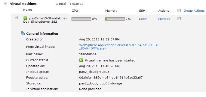
Displays basic information about the virtual machine:
- Created on
- From virtual image
- Part name
- Current status
- Updated on
- In cloud group
- Registered as
- Stored on
- In virtual application
- IBM products
-

Lists associated IBM products and license counts in PVUs
- Hardware and network
-

Displays basic information about the associated hardware and network:
- Virtual CPU count
- Virtual memory (MB)
- SSH public key
- Network interface and MAC address for each NIC
- Operating system
-

The name, type, and version of the supported operating system. Click the Show all environment variables link to display a list of defined environment variables.
- Script packages
-

Shows a list of script packages deployed to that virtual machine, including the name of the script package, the date it was last executed, a link to the associated log files and other outputs, and an Execute now button to run the script package on demand.
- Consoles
-

One or more links to available consoles you can link to. For example...

Manage virtual machine instances
Use the workload console to manage the virtual machine instances in IBM PureApplication System.
Start virtual machine instances
Virtual machines are not always running and in the started state. When a virtual machine is in the stopped state, you can restart the virtual machine to redeploy the virtual machine into the cloud. You must be granted access to the virtual appliance instance or have the Workload resources administration with full permissions to complete this task. These steps are only intended for starting a virtual machine instance that is in the Stopped state.
To create a virtual machine instance, deploy a virtual machine into the cloud.
When a virtual machine instance is stopped, the PureApplication System resources are not released and the virtual machine instance remains managed by PureApplication System. The PureApplication System resources assigned to this virtual machine instance are maintained to ensure that PureApplication System resources are available when the virtual machine instance is restarted.
-
Instances | Virtual Machines | instance | Start
Deployment of the virtual machine into the cloud does not happen instantly. The deployment time depends on the size of the virtual machine and the system activity. The Start icon is displayed while the deployment is in progress. When the state of the virtual machine is "The virtual machine instance has been deployed and is ready to use", then the virtual machine instance is running in the cloud and available for use. If the virtual machine instance does not start, the Failed icon is displayed.
Stop virtual machine instances
Virtual machine instances can be stopped without removing the virtual machine instance from PureApplication System. If a virtual machine instance is stopped, the virtual machine is not running, but management of the virtual machine is retained by PureApplication System and the virtual machine remains available for redeployment in the future. You must be granted write or all access to the virtual machine instance or have the Workload resources administration with full permissions to complete this task. When a virtual machine is stopped, the PureApplication System resources are not released.
The PureApplication System resources assigned to this virtual machine instance are maintained to ensure that the PureApplication System resources are available when the virtual machine is redeployed into the cloud.
-
Instances | Virtual Machines | virtual machine | Stop
Stopping the virtual machine instance does not happen instantly. Wait until the state of the virtual machine instance becomes Stopped to ensure that all the resources are stopped. Stopping a virtual machine instance does not release the associated resources.
The stopped virtual machine instance is no longer running but remains available for redeployment in the future. You can restart the virtual machine when you are ready.
View and modify virtual machine instances
Each deployment of a virtual machine represents a running virtual machine instance in the cloud environment. You can view or modify details for the virtual machine instances to suit the changing needs of your environment. You must be granted access to the virtual machine or have the Workload resources administration with full permissions to complete this task.
- To configure the memory and CPU of the virtual machine...
-
Instances | Virtual Machines | virtual_machine_instance | Configure icon
In the window, enter a numeric value in the Physical CPU Count, CPU Count field, and the Virtual memory (MB) field and click OK.
Change the CPU Count value to a number greater than 8 will require a restart of the instance for the change to take effect.
Change the Virtual memory (MB) size without first stopping the instance is limited to a maximum of 3 GB for instances that are currently running with less than 3 GB. Instances that are currently running with more than 3 GB of memory can be changed to 16 times the current memory capacity of the instance.
To resize an instance beyond these running limitations, complete the following steps:
- Stop the instance.
- Resize the CPU Count or Virtual memory (MB) to the wanted value.
- Start the instance.
- In the Description field, click the dotted line to enter a description for the virtual machine instance.
- In the Storage volumes field, select a storage volume from the menu.
- In the IP addresses field, select an IP address from the menu.
Monitor virtual machine instance jobs
Use the workload console to monitor virtual machine instance jobs in IBM PureApplication System W1500.
You must be assigned the role...
...with permission to...
-
View all cloud groups (Read-only)
To review jobs...
-
Workload Console | Instance | Virtual Machines | instance | Jobs | View details
Filter the jobs by either the pending or started jobs by name and type.
In the Pending Jobs section, type the name of the job in the Name field and enter the type of the job in the Type field. Click the Refresh icon. In the Started Jobs section, type the name of the job in the Name field and enter the type of the job in the Type field. Click the Refresh icon.
Administer shared service instances
Perform administrative tasks for instances of shared services for caching, monitoring, elastic load balancing (ELB), and database performance. Shared services are included in the IBM Foundation Pattern type. You can add the default shared services when you deploy the virtual application pattern. Shared services are managed via the workload console or command-line interface. The deploying task that you choose depends on the type of shared service to deploy. After deployment, you can work with the instance from the workload console Instances menu.
Grant user access to shared service instances
Administrators can use the workload console to grant user access to a shared service instance in the system.
-
Instances | Shared Services
Select a shared services instance in the left navigation window. In the main window, locate the Access granted to field. By default, the administrator is already granted access to the shared service instance. In the Add to field, click the down arrow, and select a user. The user name displays in the field for a few seconds, and then the name is added to the main list of users who have access to the shared service instance. To remove user access later, click the Remove link beside the user name.
Start and stop shared service instances
Use the workload console to start or stop a shared service.
-
Instances | Shared Services
To start a shared service instance, select a shared services instance, and click the Start icon. To stop a shared service instance, select a shared service instance, and click the Stop icon on the toolbar.
Resume shared service instances
-
Instances | Shared Services | shared services instance | Resume icon
Manage monitoring operations with shared services
Use the workload console to manage monitoring, logging, operations, and links for shared service instances.
-
Instances | Shared Services | shared service instance | Manage icon
Click the Monitoring tab to view the health of the virtual machines in this instance. Click the Logging tab to view and download the logs. Click the Operation tab to view the operations in the instance. Use this tab to update operations associated with the shared service, including:
| AGENT | To update trace settings, enter the trace string in the Trace string applied to the agent field. Enter the trace file name, such as trace.log, in the Trace File Name field. Enter the maximum file size in the Trace Max File Size field. Enter the maximum number of trace files in the Trace Max File Size field. Click the Append to trace file check box to append the trace file. Click Submit. |
| AUTOSCALING | To pause or resume auto scaling tasks, select or deselect the Pause check box and click Submit. |
| EIFRECEIVER | To start the event integration facility, click Submit. To stop the event integration facility, click Submit. |
| MONITORING | To connect or disconnect the operating system and workload monitoring agents to the monitoring service defined in the service registry, select or deselect the Connect check box. Click Submit. To start or stop monitoring of the WebSphere Message Broker, click Submit. |
| SSH | To add or update the virtual machine SSH public key, type the public key in the Public Key field and click Submit. To remove the virtual machine SSH public keys, click Submit. |
Click the Links tab to view the links in the instance. Click the Main Console tab to take you back to the main workload console.
Monitor shared service instances
Use the workload console to monitor the shared service instances deployed into IBM PureApplication System W1500.
-
Instances | Shared Services | shared services
Ability to view instances of shared services in the workload console requires that users have read-only or full cloud administration permissions. Additionally, access to each shared service instance must be granted to each individual user or to a single group of which the users are members.
IBM Tivoli Monitoring(External)
The IBM Tivoli Monitoring (External) shared service can be deployed to one or more cloud groups to provide a reference to an external Tivoli Monitoring installation Version 6.2.2 Fix Pack 5 or later. Once created, the AIX or Linux Intel OS monitoring agents and the Workload monitoring agent that are provided in the virtual application workloads are automatically connected to a defined instance of a Tivoli server by using the supplied primary and fail-over Tivoli Enterprise Monitoring Server, protocol, and port. The URL for the Tivoli Enterprise Portal Webstart console is provided, so cloud administrators are presented with a monitoring link in the Workload and Deployment consoles to launch to the Tivoli Enterprise Console.
You must install the latest Application Support and Language Pack files for the Workload monitoring agent on the Tivoli Enterprise Monitoring Server and Tivoli Enterprise Portal Server before creating the shared service and deploying patterns so that Tivoli Monitoring displays the new agents.
Delete shared service instances
Use the workload console to delete a shared service instance from the system.
When deleting the System Monitoring service, the following warning message might display in the user interface, even when the service is not used by any deployed applications:
- The shared service instance "System Monitoring" is in use, are you sure you want to delete it?
Although the System Monitoring service might not be used by any deployed applications, the service monitors itself and is therefore always running on the system. When you attempt to delete the service, the system warns you that the service is being used. You can ignore the message, as all deployed applications will continue to run even if they are being monitored by the System Monitoring service. To start monitoring the system again, restart the System Monitoring service.
-
Instances | Shared Services | shared services instance | Delete icon | OK
Administer database instances
Use the workload console to administer database instances in the system. You must be assigned one of the following roles to perform these steps:
- Workload resources administration
...with permission to...
-
Manage workload resources (Full permission)
- Workload resources administration
...with permission to...
- View all workload resources (Read-only)
- Create new patterns (only if you created and own this database)
- Create new catalog content (only if you created and own this database)
- Create new environment profiles (only if you created and own this database)
- IBM License Metric Tool (ILMT) user (only if you created and own this database)
Go to...
-
Instances | Databases
You can complete the following tasks from this pane:
- View a database
- Stop and start a database
- Upgrade a database
- Delete a database
Manage the catalog
Use this menu to manage the resources in the system catalog.
Manage reusable components
You can use the console to manage the reusable components for pattern types in the system.
Add reusable components
A reusable component is a saved configuration that can be reused to build applications. The component can be dragged onto the canvas without further configuration. You can add a reusable virtual application pattern component and associate the component with an available pattern type. Have the Create new catalog content permission or the Workload resources administration with full permissions role to complete this task.
The main purpose for reusable components is to save configuration for later reuse. For example, you can configure the attributes for an existing database component, such as database name, user name, password, and port number, and then save it as a reusable component. When you create a virtual application, this reusable component can be dragged to canvas directly without any further configuration.
- Click...
- Catalog | Reusable Components | New

- Select a pattern type and a component type from the menu, and click Next.
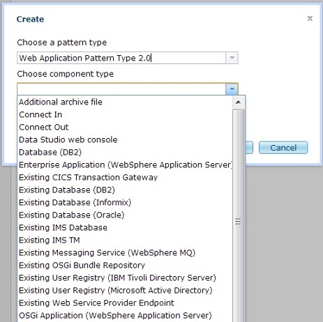
- Complete the configuration settings for the component. The information differs for each type of component that is created, including the name, server host name, IP address, user name and password, and server port number.
- Click Done.
Modify reusable components
You can edit a reusable virtual application component and associate the component with an available pattern type. The reusable components are saved in the system catalog. Have the Create new catalog content permission or the Workload resources administration with full permissions role to complete this task.
- Catalog | Reusable Components | reusable component | Edit
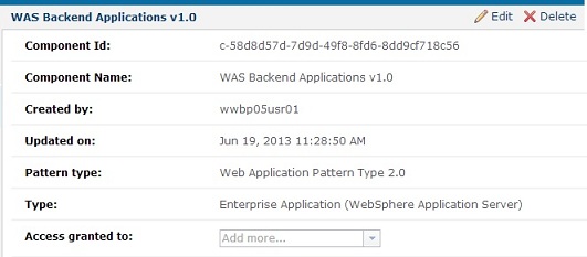
Edit the configuration settings for the component. The type of information that is requested for components is different for each type of component that is created, including, name, server host name, IP address, user name and password, and server port number.
Delete reusable application components
You can delete a reusable virtual application component from the system when it is no longer needed. Have the Create new catalog content permission or the Workload resources administration with full permissions role to complete this task.
- Catalog | Reusable Components | reusable component | Delete | OK
Manage virtual application templates
The virtual application template is a predefined set of components and configuration used to simplify and standardize the creation of virtual application patterns.
You must be assigned the either role...
-
Create new catalog content permission
Workload resources administration
...with full permissions to perform these steps. When you design a virtual application template, you can configure it with default values or leave some values unconfigured. Application builders can use the virtual application template to create new virtual application patterns. virtual application templates also provide a more flexible deployment option. When you deploy from a virtual application template, you can specify property values that are not configured or edit values that are not locked.
Create virtual application templates
You can create a virtual application template used to create a virtual application. The template can be saved in the catalog and used as a starting point to create virtual application patterns. Have the Create new catalog content permission or the Workload resources administration with full permissions to complete this task.
-
Catalog | Virtual Application Templates | New

To create the virtual application template:
- Select a pattern type from the menu.

- Select a virtual application template and click Start Building.
You created a new virtual application template associated with a pattern type. The Virtual Application Builder opens in a new window where you can add components and policies.
On the Virtual Application properties pane, specify...
- Name
- The name of the virtual application pattern.
- Description
- The description of the virtual application pattern. This field is optional.
- Type
- Leave Template selected to create a virtual application template.
- Lock option for plugin usage
- Specify how this virtual application pattern is affected by upgrades to the pattern type or to IBM Foundation Pattern.
- Unlock plugins
- If the pattern type is upgraded, use the latest versions of pattern type plug-ins. If IBM Foundation Pattern is upgraded, use the latest version.
- Lock all plugins
- Do not change the version of plug-ins or the version of the IBM Foundation Pattern associated with this virtual application pattern when an upgrade occurs.
- Lock all plugins except Foundation plugins
- If the pattern type is upgraded, do not change the version of the plug-ins that are associated with this virtual application pattern. If IBM Foundation Pattern is upgraded, use the latest version.
If you select Lock all plugins or Lock all plugins except Foundation plugins, you can view a list of which plug-ins are locked. Click the Source tab in Virtual Application Builder. The application model source is displayed. Search for the element plugins to view the list.
Create virtual applications from templates
You can use a virtual application template to create a virtual application. These templates are either templates that you created or that were shipped with the product. You can use the workload console or the REST API to complete this task. Have the Create new catalog content permission or the Workload resources administration with full permissions to complete this task. You can deploy a virtual application directly from a template or use it as a starting point to build a virtual application pattern. If you do not want to use an existing virtual application template, you can create a new virtual application template.
- Catalog | Virtual Application Templates
Select the pattern type that is associated with the template or search for the template in the left pane.
Select a template...

The following templates are available for IBM Web Application Pattern.
| Blank application | Start with a blank canvas. |
| Blank Java EE web application | Use a Java EE web application that includes WAS and DB2 database services. |
| Sample Java EE web application | use the TradeLite application, which includes WAS and DB2 database services. |
| Secured Java EE web application | Use the HitCount application, which includes Tivoli Directory Server, WAS, and DB2 database services. |
Click Open on the toolbar to edit the template.

Edit the virtual application pattern component parts:
Having trouble opening edit pane using Chrome and IE 8. Hanging. Will try Firefox next.
- Click a virtual application pattern and click the Edit icon on the toolbar.
- Select a virtual application component and drag the component onto the canvas to build the virtual application.
- To add a policy, click the Add policy for application icon.
- To create the connection between the parts, hover over one of the objects until the blue circle turns orange.
Select the circle with the left mouse button, drag a connection to the second object until the object is highlighted, and release the mouse button.
Import and export virtual application templates
You can import a virtual application template into the system catalog or export a template so that it can be imported in another system. Have the Create new catalog content permission or the Workload resources administration with full permissions to complete this task.
- Catalog | Virtual Application Templates
To import a template, click Import on the toolbar. Then, click Browse to select an application file to import.
To export a template, select a template and click Export on the toolbar.
Modify virtual application templates
You can modify a virtual application template and use it to create a virtual application pattern. The template can be saved in the catalog. The virtual application template is necessary to build the virtual application pattern that is then deployed as a virtual application instance. Have the Create new catalog content permission or the Workload resources administration with full permissions to complete this task.
-
Catalog | Virtual Application Templates | template | Open
The template opens in Virtual Application Builder.
Delete virtual application templates
You can delete a virtual application template from the system catalog when it is no longer needed. Have the Create new catalog content permission and have all access to the application template to delete. Or you must have the Workload resources administration with full permissions to complete this task.
- Catalog | Virtual Application Templates | virtual application template | Delete icon | OK
Deploy virtual application templates
You can deploy a virtual application template from the catalog. You can use an existing virtual application template, including the ones that are provided with pattern types created by IBM. You can also create new virtual application templates. Have an existing virtual application template that you created or you can use a preinstalled virtual application template. The routing policy is automatically applied to a web application when a proxy shared service is running in the same cloud group it is deploying into. Otherwise, the routing policy is not automatically added to the virtual application. You can use the Virtual Application Builder to allocate necessary components, links, and policies to application template.
- Click...
-
Catalog | Virtual Application Templates | template | Deploy icon
The Configure and deploy application dialog box displays the properties that you can configure for the selected virtual application.

- Add or modify properties as appropriate, and click OK. Required fields are marked with a red asterisk (*).
- Specify the settings for the deployment.

- IPv4 or IPv6 in the Filter by IP type field.
- Filter by profile type
- Profile
- Priority
- Cloud group
- IP group
- Expand the Advanced section to configure the advanced settings.

- The SSH key provides access to the virtual machines in the cloud group for troubleshooting and maintenance purposes.
- To generate a key automatically, click Generate.
Click Download to save the private key file to a secure location. The default name is id_rsa.txt.
The system does not keep a copy of the private key. If you do not download the private key, you cannot access the virtual machine, unless you generate a new key pair. You can also copy and paste the public key into a text file to save the key. Then, you can reuse the same key pair for another deployment. When you have the private key, make sure that it has the correct permissions (chmod 0400 id_rsa.txt). By default, the SSH client does not use a private key file that provides open permission for all users.
- To use an existing SSH public key, open the public key file in a text editor and copy and paste it into the SSH Key field.
Do not use cat, less, or more to copy and paste from a command shell. The copy and paste operation adds spaces to the key that prevent you from accessing the virtual machine.
- To generate a key automatically, click Generate.
- The SSH key provides access to the virtual machines in the cloud group for troubleshooting and maintenance purposes.
- Click OK.
When the virtual application is deployed, the virtual application instance is listed under the Instances section of the IBM PureApplication System W1500. To view the virtual instance, click...
-
Instances | Virtual Applications
- View the details of the deployed virtual application in the Virtual Application Instances pane. The details include a list of virtual machines that are provisioned on the cloud infrastructure for that deployment, the IP address, virtual machine status, and role status. Role is a unit of function that is performed by the virtual application middleware on a virtual machine.
The status values are listed in the following table:
Status Deployment description Virtual machine description LAUNCHING Virtual application is being deployed. VM is being provisioned on the infrastructure cloud. INSTALLING Not applicable The components of the virtual application are being provisioned on the VM. RUNNING Resources are being provisioned on the infrastructure cloud. The components of the virtual application are running on the VM and can be accessed. TERMINATING Virtual application instance resources are being deleted. VM is being deleted. Resources are released. TERMINATED Virtual application instance resources are deleted. History files are retained. VM is deleted and resources were released. STOPPING Virtual application instance is stopping. VM is being stopped. STOPPED Virtual application instance is stopped. The virtual application can be made available again by starting the instance. VM is stopped and it can be restarted. FAILED The deployment process could not be started because of either the application configuration or a failure that is occurring in the infrastructure cloud. VM did not start successfully. ERROR An error occurred during deployment. Check the logs and determine the cause of the error before you redeploy the virtual application. VM status. NOT_READY Virtual application instance is in maintenance mode. The NOT_READY status does not apply to VM. You can also view the virtual machine role health status information. For example, a red check mark is displayed when the amount of processor becomes critical on the VM.
Click Endpoint to view the endpoint information for a role. For a DB2 deployment, you can have more than one endpoint. For example, an endpoint for the application developer and one for the database administrator. If the elastic load balancer shared service is used by the virtual application instance, the endpoint URL is based on the virtual host name for the elastic load balancer instance. Otherwise, the endpoint URL is based on the IP address of the VM that is associated with the role.
The virtual application instance is successfully deployed and started. To stop the virtual application instance, select the virtual application from the list, and click Stop. To start the virtual application instance again, select the virtual application click Start
To redeploy a virtual application, select the virtual application and click the Deploy icon in the Virtual Application Builder pane.
To remove a stopped application, select it and click the Delete icon.
ssh to virtual machine
To access the virtual machine after deployment...
- ssh -i id_rsa.txt virtuser@<workload_ip>
To enable password-less logon to the virtual machine...
- scp -i id_rsa.txt myfiles.txt virtuser@<workload_ip>
To gain root access:
- sudo su -
To run a command with root access:
- sudo /sbin/ifconfig
You can view and monitor statistics for your deployed virtual machines and download and view the log files from the user interface.
Clone virtual application templates
You can clone a virtual application template to create a copy that you can edit and customize. The template is added to the catalog. You can use the workload console or the REST API to complete this task. Have the Create new catalog content permission or the Workload resources administration with full permissions to complete this task.
- Catalog | Virtual Application Templates | virtual application template | Clone icon | OK | Open
On the Virtual Application properties pane, specify the following information:
| Name | The name of the virtual application pattern. | ||||||
| Description | The description of the virtual application pattern. Optional. | ||||||
| Type | Leave Template selected to create a virtual application template. | ||||||
| Lock option for plugin usage | How this virtual application pattern is affected by upgrades to the pattern type or to IBM Foundation Pattern.
|
If you select Lock all plugins or Lock all plugins except Foundation plugins, you can view a list of which plug-ins are locked. Click the Source tab in Virtual Application Builder. The application model source is displayed. Search for the element plugins to view the list.
Preinstalled virtual application templates
A virtual application template is a predefined set of components and settings used to simplify and standardize the creation of virtual application patterns. A number of virtual application templates are shipped with the product.
To access the preinstalled virtual application templates:
- Click the Workload Console tab at the top of the Welcome page to open the workload console.
- Click...
- Catalog > Virtual Application Templates
The following sections describe the templates that are provided with IBM Web Application Pattern
Java Platform, Enterprise Edition (Java EE) web application
The sample Java. EE web application uses WebSphere Application Server and DB2 services to support the TraderLite Java EE web application, which simulates a stock trading system.
This template contains two virtual application components and the connection between them:
- A WebSphere Application Server web application component, which includes the tradelite.ear file
- A DB2 database component, which includes a setup_db.sql file
- In the connection between the two components, the JNDI Name of Data Source property, which is configured as jdbc/TradeDataSource, and the Two-phase TX Support property, set to false
Run the sample Java EE web application
After you use the virtual application template to create and deploy a virtual application pattern, provision two virtual machine instances, one for each cloud component. Complete the following steps after the deployed application is in the running state.
- Go to http://WAS_VM_IP/tradelite/, where WAS_VM_IP is the IP address of the deployed WebSphere Application Server virtual machine.
- Click Configuration > (Re)-populate Trade Database to populate the database.
- Click Go Trade! and register a new user ID, or use the existing user ID to log in and browse the account and portfolio.
Secured Java Platform, Enterprise Edition (Java EE) web application
The sample secured Java EE web application uses WebSphere Application Server, DB2, and Tivoli Directory Server services to support a secured Java EE web application, HitCount, which demonstrates how to increment a counter. The application is configured with the following Java EE security roles:
- The READ role allows refreshing of the state from the database and is mapped to All Authenticated.
- The UPDATE role allows an incremental count and is mapped to the manager group.
The manager group in the ldap-counter.ldif file is set up with the cn=user2,o=acme,c=us and cn=user4,o=acme,c=us users.
The sample template contains the following virtual application components and the connections between them:
- A WebSphere Application Server web application cloud component, which includes the HitCountApp.ear file
- A DB2 database component, which includes a CounterDB.sql file
- A Tivoli Directory Server user registry component, which includes a ldap-counter.ldif file. The Base DN property is configured as o=acme,c=us.
- In the connection between the application and database components, the JNDI Name of Data Source property, which is configured as jdbc/counterDB, and the Two-phase TX Support property, set to false.
- In the connection between the application and LDAP components, the User Filter property, which is configured
as (&(uid=%v)(objectclass=ePerson)), and the Group Filter property, which is configured
as (&(cn=%v)(|(objectclass=groupOfNames)(objectclass=groupOfUniqueNames))).
The default value for the object class is groupOfUniqueNames. This value cannot be changed.
Run the sample secured Java EE web application
After you use the template to create and deploy a virtual application pattern, provision three virtual machine instances, one for each cloud component. Complete the following steps after the deployed application is in the running state:
- Go to http://WAS_VM_IP/hitcount or https://WAS_VM_IP/hitcount, where WAS_VM_IP is the IP address of the deployed WebSphere Application Server virtual machine.
- Log in using user1/user1 or user3/user3 to try the read actions.
- Log in using user2/user2 or user4/user4 to try the update actions.
Administer virtual images
You can administer virtual images to provide the operating system and product binary files required to create a virtual system instance. Have access to the virtual image or have the Workload resources administration with full permissions to complete this task.
Import virtual images to the catalog
You can expand the collection of virtual images on the system by importing additional virtual images, provided by IBM, to the catalog.
You must be assigned full permissions to either role...
-
Create new catalog content permission
Workload resources administration
Some restriction apply to images that can be deployed. Virtual images can be added to the catalog from two different sources.
- You can download new virtual images from IBM and then import them into the catalog. These images can be new or they can be service-level updates. If the imported image is a service-level update to an image that is provided by IBM, the update is added to the catalog as an emergency fix. You can use this emergency fix to upgrade all the virtual systems that you created to the current service level.
- You can also add virtual images that you exported from another system. After you export a virtual image, it can be added to the catalog of a different system. If you extended a virtual image on a system, the extended virtual image can be shared across the system. The extended image is shared by exporting the virtual image from the original system and adding the virtual image to the other catalogs.
You can use the workload console or the command line interface to complete this task.
- Click...
- Catalog | Virtual Images | New
- On the window that is displayed, enter the remote path of the virtual image to import in the OVA file location field.
The format can be either HTTP URL, for example, http://server.company.com, or Secure Copy Protocol (SCP), for example, server.company.com.
- Optional: Enter the user name in the User name field.
This field is required only if the location of new virtual image is secured with a user name and a password.
- Optional: Enter and verify the password in the Password and Verify password fields.
A password is required only if the location of new virtual image is secured with a user name and a password.
If you are getting the following message: The name or identifier you entered is already in use, an image matching the name, build and version of the image being loaded already exists. Request access to that image or get access from an authorized user to view all images.
What to do next
The new virtual image is now available in the catalog and can be used to create patterns.
Clone virtual images
You can clone a virtual image to create a copy of an existing virtual image in the catalog. You can create a clone of an existing virtual machine to handle increased workload.
Have full permissions for either of the following roles
- Create new catalog content permission
- Workload resources administration
You can clone various images that are in the catalog. Note, however, that for IBM WebSphere Application Server Hypervisor Edition Intelligent Management Pack images, you can clone only those that are version 7.0.0.11 or later.You can use the workload console or the command line interface to complete this task.
- To create a copy of the selected virtual image.
-
Catalog | Virtual Images | virtual image | Clone icon
- Modify the general information for the copy of the virtual system.
To modify the content of the virtual image, you must extend the virtual image. You cannot alter a NIC in the workload console after an image is cloned.
- Expand the General Information section.
- Enter the name of the new virtual image.
- Optional: Enter a description for the new virtual image.
- Enter the version of the new virtual image.
- Modify the Hardware configuration.
- Expand the Hardware configuration section.
- The initial size of each disk in the cloned image is the same size as in the original image. You can optionally specify a larger amount of storage needed, in GB, in the associated image (GB) field. You can increase the disk size, but you cannot specify a smaller amount.
Images containing disks with EXT4 partitions or that use LVM cannot be resized once they are imported.
- Click OK.
A new virtual image is created, followed by an attempt to create a virtual machine from this image.
- To view the creation progress of the virtual machine, and any errors...
-
Instances | Virtual Systems | History
After deploying an image with storage volumes that have been increased in size, you must also run a set of commands to increase the size of the filesystem to use the additional space. Note that you must run these commands each time you deploy the image. To avoid having to run these commands every time, you can extend the virtual image, run these commands once, and then capture the image. You can then use the captured image repeatedly without needing to run these commands each time.
You can also add disks to a virtual machine after it has been deployed, by using console ...
-
Instances | Virtual Machines | Virtual Machine pane
You can use your new virtual image to create virtual system patterns.
Extend partition and file system sizes
If you clone a virtual image and increase the size of one or more disks in the image, you need to run a set of operating system commands to extend the size of the partition and file system to use the additional disk space.
Use this procedure if you previously cloned a copy of the image and configured the disk sizes to be larger than in the original image.
Every time you deploy the cloned image, you must perform this procedure. However, to avoid having to run these commands each time, extend the cloned image, run this procedure, and then capture the image. You can then use this captured image repeatedly without having to run the commands every time.
This task describes the procedure to extend the partition and file system size to use the additional disk space that you specified in your cloned image. This procedure is designed with the following assumptions:
- The partition that is being manipulated is the only partition on that disk.
- The partition is not the root partition.
By way of example, the following procedure describes the steps for extending the size of /opt/IBM/AppServer/profiles on a WebSphere Application Server Hypervisor Edition virtual image.
- Log on to the deployed virtual machine and stop the running instance of WebSphere Application Server Hypervisor Edition.
-bash-4.1# cd /opt/IBM/WebSphere/AppServer/bin
-bash-4.1# ./stopServer.sh server1
ADMU0116I: Tool information is being logged in file            /opt/IBM/WebSphere/Profiles/DefaultAppSrv01/logs/server1/stopServer.log
ADMU0128I: Starting tool with the DefaultAppSrv01 profile ADMU3100I: Reading configuration for server: server1
ADMU3301I: Server stop request issued. Waiting for stop status.
ADMU4000I: Server server1 stop completed.
- Use the df -h command to list the file systems and identify which file system is associated with /opt/IBM/WebSphere/Profiles.
-bash-4.1# df -h
Filesystem            Size  Used Avail Use% Mounted on /dev/sda1             9.9G  4.2G  5.3G  45% /
tmpfs                 937M  176K  937M   1% /dev/shm
/dev/sdb1             7.9G  3.9G  3.7G  52% /opt/IBM/WebSphere/AppServer
/dev/sdc1             2.0G  610M  1.3G  32% /opt/IBM/WebSphere/Profiles
/dev/sdd1             2.0G  507M  1.4G  27% /opt/IBM/HTTPServer
From this list, note that the /opt/IBM/WebSphere/Profiles directory is associated with the /dev/sdc1 file system.
- Use the fdisk -1 command to list the disks and partitions, and identify the partition associated with the selected file system.
-bash-4.1# fdisk -1

Disk /dev/sda: 12.9 GB, 12884901888 bytes
255 heads, 63 sectors/track, 1566 cylinders
Units = cylinders of 16065 * 512 = 8225280 bytes
Sector size (logical/physical): 512 bytes / 512 bytes
I/O size (minimum/optimal): 512 bytes / 512 bytes
Disk identifier: 0x00005a0f

   Device Boot      Start         End      Blocks   Id   System /dev/sda1   *           1        1306    10484736   83   Linux
/dev/sda2            1306        1567     2097152   82   Linux swap / Solaris

Disk /dev/sdb: 8589 MB, 8589934592 bytes
255 heads, 63 sectors/track, 1044 cylinders
Units = cylinders of 16065 * 512 = 8225280 bytes
Sector size (logical/physical): 512 bytes / 512 bytes
I/O size (minimum/optimal): 512 bytes / 512 bytes
Disk identifier: 0xe5886cba

   Device Boot      Start         End      Blocks   Id   System /dev/sdb1               1        1044     8385898+  83   Linux

Disk /dev/sdc: 12.9 GB, 12884901888 bytes
255 heads, 63 sectors/track, 1566 cylinders
Units = cylinders of 16065 * 512 = 8225280 bytes
Sector size (logical/physical): 512 bytes / 512 bytes
I/O size (minimum/optimal): 512 bytes / 512 bytes
Disk identifier: 0x47c0b2bc

   Device Boot      Start         End      Blocks   Id   System /dev/sdc1               1         261     2096451   83   Linux

Disk /dev/sdd: 2147 MB, 2147483648 bytes
255 heads, 63 sectors/track, 261 cylinders
Units = cylinders of 16065 * 512 = 8225280 bytes
Sector size (logical/physical): 512 bytes / 512 bytes
I/O size (minimum/optimal): 512 bytes / 512 bytes
Disk identifier: 0xdc97d4d3

   Device Boot      Start         End      Blocks   Id   System /dev/sdd1               1         261     2096451   83   Linux
From this output, note the following partition information:
Device Boot Start End Blocks Id System /dev/sdc1 1 261 2096451 83 Linux
- Use the umount command to unmount the partition.
-bash-4.1# umount /dev/sdc1
- Use the fdisk command to extend the partition.
- Run the fdisk -u command to open the partition table for the disk in sector mode.
-bash-4.1# fdisk -u /dev/sdc
- Type p at the prompt to list the partitions on the disk.
Command (m for help): p

Disk /dev/sdc: 12.9 GB, 12884901888 bytes
255 heads, 63 sectors/track, 1566 cylinders, total 25165824 sectors
Units = sectors of 1 * 512 = 512 bytes
Sector size (logical/physical): 512 bytes / 512 bytes
I/O size (minimum/optimal): 512 bytes / 512 bytes
Disk identifier: 0x47c0b2bc

   Device Boot      Start         End      Blocks   Id   System /dev/sdc1              63     4192964     2096451   83   Linux
Note the value of the starting sector (63). You will need this value later when you recreate the partition.
- Type d to delete this partition.
Command (m for help): d
Selected partition 1
- Type n to recreate the partition.
Command (m for help): n
- Type p to select the primary partition type.
Command action    e   extended
   p   primary partition (1-4)
p
- Type 1 to select partition number 1.
Partition number (1-4): 1
- Specify the first sector using the same value (63) previously
noted for the starting sector.
You must specify the same value for the starting point as before. Otherwise, you can no longer mount or use the file system.
First sector (63-25165823, default 63): 63
- Specify the last sector for the partition end point
to extend the partition to the full space available on the disk.
Last sector, +sectors or _size{K,M,G} (63-25165823, default 25165823): 25165823 - Type p to list the updated partitions
and verify the changes.
Command (m for help): p

Disk /dev/sdc: 12.9 GB, 12884901888 bytes
255 heads, 63 sectors/track, 1566 cylinders, total 25165824 sectors
Units = sectors of 1 * 512 = 512 bytes
Sector size (logical/physical): 512 bytes / 512 bytes
I/O size (minimum/optimal): 512 bytes / 512 bytes
Disk identifier: 0x47c0b2bc

   Device Boot      Start         End      Blocks   Id   System /dev/sdc1              63    25165823    12582880+  83   Linux
This output shows that the End value changed from 4192964 to 25165823, and the number of blocks increased from 2096451 to 12582880+.
- Type w to save the changes.
Command (m for help): w
The partition table has been altered!

Calling ioctl() to re-read partition table.
Syncing disks.
-bash-4.1#
- Run the fdisk -u command to open the partition table for the disk in sector mode.
- Use the e2fsck command to check the partition and verify that there are no errors.
-bash-4.1# e2fsck -f /dev/sdc1
e2fsck 1.41.12 (17-May-2010)
Pass 1: Checking inodes, blocks, and sizes
Pass 2: Checking directory structure
Pass 3: Checking directory connectivity Pass 4: Checking reference counts
Pass 5: Checking group summary information /dev/sdc1: 2997/131072 files (0.5% non-contiguos), 164355/524112 blocks
- Use the resize2fs command to extend
the file system to consume all additional space on the partition.
-bash-4.1# resize2fs /dev/sdc1
resize2fs 1.41.12 (17-May-2010)
Resizing the file system on /dev/sdc1 to 3145720 (4k) blocks.
The file system on /dev/sdc1 is now 3145720 blocks long.
- Use the mount command to mount the partition.
-bash-4.1# mount /dev/sdc1 /opt/IBM/WebSphere/Profiles
- Use the df -h command to list the file systems again.
-bash-4.1# df -h
Filesystem            Size  Used Avail Use% Mounted on /dev/sda1             9.9G  4.2G  5.3G  45% /
tmpfs                 937M  176K  937M   1% /dev/shm
/dev/sdb1             7.9G  3.9G  3.7G  52% /opt/IBM/WebSphere/AppServer
/dev/sdd1             2.0G  507M  1.4G  27% /opt/IBM/HTTPServer
/dev/sdc1              12G  612M   11G   6% /opt/IBM/WebSphere/Profiles
From this list, note that the size of /dev/sdc1 increased from 2.0G to 12G, and the available space has increased from 1.3G to 11G.
- Start the server.
-bash-4.1# ./startServer.sh server1
ADMU0116I: Tool information is being logged in file            /opt/IBM/WebSphere/Profiles/DefaultAppSrv01/logs/server1/startServer.log
ADMU0128I: Starting tool with the DefaultAppSrv01 profile ADMU3100I: Reading configuration for server: server1
ADMU3201I: Server launched. Waiting for initialization status.
ADMU3000I: Server server1 open for e-business; process id is 7743
What to do next
After you complete the procedure, your deployed image can now take advantage of the larger disk space.
If you performed this procedure after you extended the clone image, capture the image with these changes so that you can use the image repeatedly without having to complete these steps again.
Extend and capture virtual images
You can use the workload console to create custom virtual images by extending a virtual image. Extending a virtual image is the process of starting with a copy of a virtual image, modifying it, and storing the modified image as a new virtual image in the catalog. To complete this task, you must have either the Create new catalog content permission and be granted all access to the virtual image you want to extend, or have the Workload resources administration with full permissions.
The DataPower virtual image cannot be extended because it is a security appliance and does not support configuration using ssh. You can use an existing virtual image to add new virtual images to the catalog. A copy of an existing virtual image is created and a default pattern from that virtual image is automatically deployed into the cloud to create a virtual system instance. You can then log in to the virtual system instance, modify the product environment or operating system, and store the changes in the new virtual image. After making the changes, return to the workload console and store the changes. The changes made to the virtual system instance are copied from the hypervisor to the system. A new virtual image is created based on that virtual system instance.
You cannot take a snapshot and then capture the image. You can use the workload console or the command line interface to complete this task.
- Click...
- Catalog | Virtual Images | image | Extend icon
- Enter the field values for the General information and Deployment configuration sections and click OK.
- Expand the General Information section. Complete the following details:
Name Display name for the virtual image. All references to this image in the workload console are made by using this name. Description Text description of the virtual image. Optional. Version Version of the virtual image. This required field can be set when the virtual image is cloned in the catalog. The version of the virtual image is propagated down to parts on a pattern. You can change the version on an individual part or on the editing canvas.
- Expand the Deployment configuration section. Complete the following details:
IP version IPv6 or IPv4. Choose profile Select the profile to use. Choose cloud Select the cloud to use. IP Group Select the IP group to use. Password Password for the default user on the virtual system instance, and the root user. The default user is virtuser. Verify Password Value entered in the password field is correct. A virtual system instance is created by using the default pattern. You can modify this virtual system instance and then capture the modifications into a new virtual image. After you click OK, the virtual image status displays the following message:
- Create a virtual system instance for virtual image extension
A virtual system instance with the name Copy of <virtual_image_name> is deployed into the cloud.
- Expand the General Information section. Complete the following details:
- Click the Copy of <virtual_image_name> link to display the details of the new virtual system instance and to verify that the virtual system instance is successfully deployed into the cloud.
The deployment does not happen instantly. The time it takes for deployment is dependent on the size of the virtual image and the system activity in progress. When the progress icon is displayed, deployment is still in progress. When deployment is completed, the started icon is displayed.
Do not click the Start icon to start the virtual system instance. If you click the Start icon, the virtual system instance might fail.
- Log in to the virtual system instance and configure the new virtual image.
You cannot resize a disk and alter a NIC in the workload console after an image is extended. You can, however, add disks to a virtual machine after it has been deployed, by using the workload console...
-
Instances | Virtual Machines | Virtual Machine
Changes made at the WebSphere Application Server profile level are not retained when you create a virtual image based on this virtual system instance.
- Catalog | Virtual Images | Capture icon | OK
The capture process creates a new virtual image based on the deployed virtual system instance that you modified. This process takes time to complete because a large amount of processing is required. Multiple image captures can be scheduled and added to the task queue, but no more than two image captures are performed concurrently. The reason for the limited captures is because of resource limitations on the system and the large amount of data processing. The Comments and the Access granted to field values are not captured as part of the new image. When working with AIX images, to capture changes in /tmp, you need to change /etc/exclude.rootvg before the capture.
Click the Lock icon to permanently make this virtual image read-only. If the new virtual image is in draft mode when you delete it, the virtual system instance created with the extend process is also deleted. The new virtual image can be used for pattern creation. The new virtual image that you created can also be exported and added to the catalog of other systems.
View and modify virtual images
You can edit a virtual image and save the changes in the IBM PureApplication System W1500 catalog.
If you are viewing a virtual image for the first time, you must accept the license. With some images, multiple license options are available, which allows you to account for operating system licenses that you purchased.
Because patterns are associated with virtual images, you might have to accept a license before you can clone a pattern associated with that image. If you accept a license that you do not intend to use to clone the pattern, and you change the cloned pattern to use another image, you are not charged for the license usage.
Have the Create new catalog content permission or the Workload resources administration with full permissions to complete this task.
-
Catalog | Virtual Images | virtual image
Edit or complete the following fields:
| License agreement | Accept the license. If it is already accepted, click view. A window displays that lists all of the licenses that are accepted. You can click on each product name to learn more about the license agreement. Click OK to return to the Virtual Images pane. |
| Intelligent Management Pack | In the menu, select Enable or Disable the Intelligent Management Pack. There are additional costs for this feature. |
| Product IDs | Click Click to add and describe the product ID to add. Enter the product ID in the Product ID field and the license type in the License type field. Click OK. |
| Contains parts | Click show more to view the parts in the virtual image. Click part product IDs to view the part product IDs for each part. |
| Access granted to | Click Add more to give access to more users. |
| Comments | Click Add a comment to attach comments to this virtual image. |
Delete virtual images from the catalog
You can delete a virtual image from the catalog.
To complete this task, you must either have the Create new catalog content permission and be granted all access to the virtual image to delete, or have the Workload resources administration with full permissions. When you delete a virtual image, any patterns that refer to that virtual image are no longer deployable. You must clone these patterns and link them to a new virtual image before they can be deployed. You can use the workload console or the command line interface to complete this task.
- Click...
-
Catalog | Virtual Images | virtual image
- Verify that the virtual image selected is not currently being used by any of the virtual system instances managed by the system.
If a virtual system instance that is referencing that virtual image is currently running, the virtual image cannot be deleted. To confirm that a virtual image is not being used in the cloud, ensure that the In the cloud now field does not show any virtual system instances ((none) is displayed).
- Click the Delete icon on the toolbar.
- Click OK.
Clone any patterns that referenced the virtual image that you removed. You must link these patterns to a new virtual image before they can be deployed.
Export virtual images
Virtual images can be exported from the catalog to be used on other systems.
To complete this task, you must have either the Create new catalog content permission and be granted all access to the virtual image you want to copy, or have the Workload resources administration with full permissions.
The virtual image is exported to a remote server by Secure Copy Protocol (SCP). SCP copies files and directories securely between remote hosts without starting an FTP session or logging into the remote systems explicitly. Ensure that space is available for the exported virtual image. When you export a virtual image, the OVA file will be saved in the following manner; if the path ends with .ova, the file is saved to that location. Otherwise, the OVA file will be saved with the default name in the directory specified by the Remote path field. Any directories in the path that do not already exist will be created. You can use the workload console or the command line interface to complete this task.
- Click...
- Catalog | Virtual Images | virtual image | Export
- In the Remote host field, enter the host name of the remote host to which the virtual image will be exported.
- In the Remote path field, enter the remote path where the virtual image will be stored.
- In the User name field, enter the user name that SCP will use to transfer the files to the virtual machine.
- In the Password and Verify password fields, enter the password for the user.
- Click OK.
You can now import the exported virtual image to the catalog of another system.
Tune the Windows Server 2008 R2 virtual image
You can apply these performance improvements to the virtual image by using either...
- Image Construction and Composition Tool
- The virtual image extend and capture function in the workload console.
To disable Windows services that are not used in your environment, go to...
-
Start | Administrative Tools | Services
...and select services to disable. For example, the following list includes services that may not be used. You might also determine that additional services not included in the list should be disabled:
- Background Intelligent Transfer Service
- Certificate Propagation
- Print Spooler
- Shell Hardware Detection
- Windows Firewall
- Windows Update
- Power
- Remote Desktop Configuration
- Remote Desktop Services
- Remote Desktop Services UserMode Port Redirector
Ensure that you are conforming to your local security policy before you disable any security related service.
To disable hardware devices and hardware configuration settings that do not typically apply when you are using a virtual server, such as display adapters, diskette drives, diskette controllers, monitors, system speakers, and the COM and LPT ports. Go to...
-
Start | Control Panel | Hardware | Devices and Printers | Device Manager
To configure Windows performance settings for visual effects and data protection, go to...
-
Start | Control Panel | System and Security | System | Advanced system settings | Advanced | Performance | Settings
On the Visual Effects tab, select the option...
-
Adjust for best performance
By doing so, all Custom options are then cleared. The Smooth edges of screen fonts and Use visual styles on windows and buttons options might be automatically selected when the image is deployed, but no action to clear these options is required.
To configure the security and data protection of certain Windows programs and services, on the Data Execution Prevention tab, select the option...
-
Turn on DEP for essential Windows programs and service only option
Ensure that you are conforming to your local security policy before you select this option.
You disable Remote Desktop related services if your business needs do not require Remote Desktop connections. The specific services that you can disable are Remote Desktop Configuration, Remote Desktop Services, and Remote Desktop Services UserMode Port Redirector.
If you require Remote Desktop connections, you can improve your deployment times by disabling only the Remote Desktop Services UserMode Port Redirector service, which is used to redirect printers, drivers, and ports for Remote Desktop connections. Disabling this service does not prevent a Remote Desktop session from being established with a Remote Desktop client. If you require the use of the Remote Desktop Services UserMode Port Redirector service, disable it in the Windows virtual image, and then enable and start the service after you deploy the image.
To update the settings for Windows Error Reporting and Windows Customer Experience Improvement Program.
- To choose not to participate in Windows Error Reporting, go to...
-
Initial Configuration Tasks | Update This Server | Enable automatic updating and feedback | Manually configure settings | Windows Error Reporting | Change Setting
- To choose not to participate in the Customer Experience Improvement Program, go to...
-
Initial Configuration Tasks | Update This Server | Enable automatic updating and feedback | Manually configure settings | Customer Experience Improvement Program | Change Setting
To Disable the Windows screen saver, go to...
-
Start | Control Panel | Appearance | Display | Change screen Saver
Select (None) option from the Screen saver list, and click OK.
To disable the Windows Welcome screen, go to...
-
Start | Administrative Tools | System Configuration | Boot | No GUI boot
Fields on the Virtual Images pane
Use the following fields when you are working with a virtual image:
- Description
- Text description for the virtual image.
- Created on
- Date when this virtual image was created.
- Current status
- State of the virtual system instance.
- Updated on
- Date when this virtual image was last updated.
- License agreement
- Specifies if the license agreement to use this virtual image is accepted. If the license agreement is not accepted, the virtual images are not displayed in the menu to be used in a pattern.
- Intelligent Management Pack
- Specifies if WebSphere Application Server Intelligent Management Pack is enabled for the virtual image. The default value for this field is Disabled.
- Hypervisor type
- Type of hypervisor the virtual image requires. Set to VMware ESX when the virtual image is created. Cannot be modified.
- Operating System
- Specifies the guest operating system for the virtual image.
- Version
- Version of WebSphere Application Server that is included in the virtual image. Though this required field can be set to any value, it must contain a valid version of WebSphere Application Server. You can set the field when you clone the virtual image in the catalog.
The version of the virtual image is propagated down to parts on pattern by using the virtual image. You can change the version of an individual part on the editing canvas.
- Image reference number
- Specifies the WebSphere Application Server build number for the virtual image. This field is set when the virtual image is created and cannot be modified.
- Product IDs
- IBM product
ID of the product or products included in the virtual image.
The rules for adding or deleting product IDs in virtual images are listed as follows:
- Set a virtual image as read-only does not inhibit the ability to add or delete product IDs in the virtual image.
- Product IDs can still be added or deleted if a virtual image is included in a pattern.
- Product IDs cannot be added or deleted from any virtual image deployed in the cloud.
- Contains Parts
- Available parts for the virtual image. Parts that are not available because advanced options are not enabled are marked as inactive.
- In the cloud now
- Specifies a list of links to all the virtual system instances that were created by using patterns constructed with this virtual image. You can click any virtual system name to display the details for that virtual system instance.
- Access granted to
- The creator of a virtual image is automatically granted all access to the virtual image as the owner. If you want additional users to access this virtual image, manually grant access to those users.
- Extended from
- Displays a link to the virtual image that was used to create this virtual image. This field is not displayed unless this virtual image was created as an extension of another virtual image.
- Hardware
- Expand this section to view additional details about the hardware configuration of the virtual image.
- Virtual CPU count
Number of processors the virtual image represents.
- Virtual machine memory (MB)
Amount of memory, in megabytes, on the hypervisor that this virtual machine is allocated. This value is specified in the pattern that was deployed to create the virtual system instance.
You cannot resize the disk or modify a network interface controller (NIC) from the workload console after an image is cloned and extended. However, you can add disks to a virtual machine after it has been deployed from the workload console Virtual Machine pane. Click...
-
Instances > Virtual Machines
- Virtual CPU count
- Comments
- Specifies additional comments about a virtual image.
Configure the system
Configure system settings
Configure settings for your system, such as the DNS server, email delivery, date and time, event forwarding, and backup and restore operations.
Administer the DNS server
A DNS server is required for the system to function correctly, as DNS lookup services are used for communication. You are required to specify the DNS server during system initialization. You must be assigned the role...
Your DNS servers must have forward and reverse DNS entries for the range of IP addresses being managed by the product, which uses the derived host name from the reverse lookup during deployment of a virtual system instance. All DNS servers must support both forward and backward resolution of host names and IP addresses. If a reverse lookup fails because no host name is defined, the deployment fails. Deployed virtual machines can be configured with multiple DNS servers.
- Assign the administrator the role...
...with permission to...
-
Manage hardware resources (Full permission)
- Click...
-
System > Settings
- Expand DNS.
- To add a DNS server, enter its address and click Add > Save.
- To look up a host name or IP address, type the host name or the IP address and click Lookup.
- To delete a DNS server, click the corresponding Delete icon.
Configure email delivery
Configure the required Simple Mail Transfer Protocol (SMTP) server and the password reset notices.
- Assign the administrator the role...
...with permission to...
-
Manage hardware resources (Full permission)
- Click...
-
System > Settings
- Expand Mail Delivery.
- Enter the IP address or the host name of the SMTP server. This server is used by the system to send email messages. If you enter a host name, the host name must be resolved by the DNS servers that are defined in the system.
- Specify the email address to be used as the reply-to address for email messages.
Typically, this address is the email address of the system administrator. This address is used as the sender of the generated email messages for various events. The following events can generate email notifications:
- User ID creation
- Password reset
- Completion of system backup.
The email message is sent to the email specified for the default administrator account on the system. To view this account, click...
-
System | Users | admin
Configure date and time settings
Use Network Time Protocol (NTP) servers to maintain a synchronized time and date across your system. An NTP server can automatically synchronize the system clock for accurate timekeeping, and propagate the time to the workloads deployed in the system.
Configure the NTP server to be accessible by the system. An NTP server, which is accessible by the virtual machines, is required to successfully deploy a virtual application pattern or virtual system pattern. When virtual application patterns or virtual system patterns are deployed, the NTP server is used to establish the system time for the virtual machines. Without a synchronized date and time, problems can occur, resulting in incomplete deployments or failure to start the instances. If an NTP server is not used, the system clocks for the system must be synchronized manually.
- Assign the administrator the role...
...with permission to...
-
Manage hardware resources (Full permission)
- Click...
-
System | Settings
- Expand Date and Time.
- Enter the IP address of the NTP server in the NTP server address field. You must enter an IP address. You cannot use the host name. In addition, these IP addresses are not editable. If you want to change it, you must delete the existing entry and add another one.
- Click Add. By default, no NTP servers are configured.
- If you have more than one NTP servers, you can use the up and down arrows to reorder them. The first available server in the list is used to maintain synchronization.
- Click Save.
Configure event forwarding
Configure events as Simple Network Monitoring Protocol (SNMP) traps.
Configure the system details
As part of configuring event forwarding, you must set your system information so your system is correctly identified.
- Assign the administrator the role...
...with permission to...
-
Manage hardware resources (Full permission)
- Click...
-
System | Settings | Event Forwarding
- In the System Identification table, complete the following fields:
- PureApplication System name
- Name used to identify the system. This information is included with SNMP alert notifications to identify the source of the alert.
- PureApplication System contact
- Name and phone number of the contact for this system if there are problems.
- PureApplication System location
- Physical location of the system so that it can be quickly located for maintenance.
- Click Save.
Download MIBs
An MIB is a virtual database used for managing entities in a communications network used with SNMP. To use Simple Network Monitoring Protocol (SNMP) to monitor the status of a system that is part of a large group of systems in a data center, you must download a management information base (MIB).
- Assign the administrator the role...
- Click...
-
System | Settings | Event Forwarding | Download MIB
- Save the .zip file to your local system.
...with permission to...
-
Manage hardware resources (Full permission)
Download OMNIbus rules
OMNIbus rules provide a mechanism to collect event data by using high performance software probes. You can download the OMNIbus rules to work with SNMP monitoring. Use the system console to complete this task.
- Assign the administrator the role...
...with permission to...
-
Manage hardware resources (Full permission)
- Click...
-
System | Settings | Event Forwarding
- In the Trap Destinations section, click Download OMNIbus Rules. Save the .zip file to your local system.
Create and deleting SNMP trap destinations
Events are configured as SNMP trap subscribers and are used to access the Simple Network Monitoring Protocol (SNMP) data on your system. When no longer needed, you can delete SNMP trap destinations.
- Assign the administrator the role...
...with permission to...
-
Manage hardware resources (Full permission)
- Click...
-
System | Settings | Event Forwarding
...and find the Trap Destinations section.
- To create a trap destination, click Create trap destination and complete the fields in the window:
IP address IP address where the SNMP client listens for trap information. Port number Port on which the SNMP client is listening for trap information. The default value is 162. Community SNMP community of which the client is a member. The default value is public. SNMP version SNMP version used for trap communication. The options for this field are 1 and 2c. Minimum event severity SNMP severity from the available options. - Click OK and click Save.
- To delete a trap destination, select it from the list and click the Delete icon.
You cannot modify SNMP trap destinations. If you want to modify a trap destination, you must delete it and then create another one.
Set the time interval for events
You can set the time interval for events.
- Assign the administrator the role...
...with permission to...
-
Manage hardware resources (Full permission)
- Click...
-
System > Settings
- Expand Time Interval and click the menu to select a value for the time interval.
The values in the upper right of the console display the total number of warning and error events that occurred within the configured time interval. When you click a value, a sample of events is displayed. To display all events that occurred within the configured time interval, click View All.
Configure network settings
Use network settings to configure VLAN ranges, link aggregation, and management and deployment functions of the system.
Configure network ports
To set up network ports, you must select at least 2 cables and at most 32 cables. Each individual cable can be a 1 GB copper or a 10 GB copper/fiber. The bandwidth of these cables can run from 2 to 320 GB, as different combinations of 1 and 10 Gb are chosen. Symmetric connections are recommended, which you can achieve by choosing the same ports on the A and B switches. This approach ensures better traffic flow, easier debugging, and a resilient network configuration.
Assign the administrator the role...
...with permission to...
-
Manage hardware resources (Full permission)
-
System | Customer Network Configuration | Network | Port Setup | port | Edit
You can select one of the following options:
- Empty
- 1 GB SFP Fiber
- 1 GB SFP Copper
- 10 GB SFP+Fiber
- 10 Gb SFP+DAC
Configure VLAN information
PureApplication System supports 802.1Q VLAN technology to isolate network traffic. This VLAN information covers both the management VLAN, and any data VLANs that exist. You can configure a VLAN range used exclusively for testing purposes, and another VLAN range used primarily for development.
- Assign the administrator the role...
...with permission to...
-
Manage hardware resources (Full permission)
- Click...
-
System | Customer Network Configuration
- To enter the VLAN range information, expand Network and scroll down to the VLAN Information section.
- Optional: Select the Enable spanning tree (PVRST) check box to enable PVRST. The PVRST mode is based on Rapid Spanning Tree Protocol (RSTP) to provide rapid spanning tree convergence. PVRST supports instances of spanning tree, allowing one STG per VLAN. PVRST mode is compatible with Cisco R-PVST/R-PVST+ mode. PVRST is the default spanning tree mode on IBM RackSwitch G8264.
- Click Add.
- Review the internal network VLANs. These values are chosen during system configuration and cannot be changed. They are displayed here to help you avoid conflicts with your networks.
- Click Save and click OK.
There is only one Save button for all Network settings. The button is at the end of the Network section.
Configure link aggregation (1 and 10 GB)
All ports must be aggregated with at least one port from each switch. Link aggregation provides better aggregation throughput and redundancy. Use the system console to configure link aggregation for external access network ports in IBM PureApplication System W1500.
You must be assigned the role...
...with permission to...
-
Manage hardware resources (Full permission)
To configure...
-
System | Customer Network Configuration | Network | Link Aggregation | port | Aggregate | Save | OK
There is only one Save button for all Network settings. The button is at the end of the Network section.
Configure aggregated port links
After you aggregate port links, you can configure the links to distribute the traffic to the various ports in trunk groups.
Two trunk types are available: static trunk groups (PortChannel), and dynamic Link Aggregation Control Protocol (LACP) trunk groups. Trunk traffic is distributed among the ports in a trunk group, which is based on various configurable options. Because each trunk group includes multiple physical links, the trunk group is inherently fault tolerant. While one connection between the switches is available, the trunk remains active, and statistical load balancing is maintained whenever a port in a trunk group is lost or returned to service.
- Assign the administrator the role...
...with permission to...
-
Manage hardware resources (Full permission)
- Click...
-
System > Customer Network Configuration | Network | Link Configuration section
- Find the link to configure and click Edit.
- Configure the following fields:
- Flow control mode
- Select Enable or Disable from the menu.
- VLAN mode
- Select Tagging or No Tagging from the menu.
- Link aggregation method
- Select LACP or Ethernet channel from the menu.
- VLAN range
- Specify the VLAN range fields. Click Add.
- Click Save and click OK.
There is a single Save button for all Network settings, which is at the end of the Network section.
Configure management ports
To access the management and deployment functions for the system, you must configure IP address types for the management LAN port.
- Assign the administrator the role...
...with permission to...
-
Manage hardware resources (Full permission)
- Click...
-
System | Customer Network Configuration
- Expand Management LAN port.
- To configure the management ports, in the Management
Ports table, set the connection type for IBM RackSwitch G8264 A and RackSwitch G8264 B.
Both switches use Port 64. Select one the following connection types:
- 1 GB SFP Fiber
- 1 GB SFP Copper
- 10 GB SFP+ Fiber
- 10 GB SFP+ DAC
- Select the Aggregate Port
64 check box. You can configure the following fields:
- Flow control mode
- Select Enable or Disable from the menu.
- VLAN mode
- Select Tagging or No Tagging from the menu.
- Link aggregation method
- Select LACP or Ethernet channel from the menu.
- Enter the VLAN information.
- Click Save and click OK.
There is a single Save button for all Management LAN Port settings, which is at the end of the Management LAN Port section.
Configure management IP addresses
The management IP address is the network connection used to access the management and deployment functions of the system. Teams that use the system to deploy workloads and hardware administrators enter through this management address to interact with the systems.
You can configure the management LAN port with either an IPv6 or IPv4 address, but they must be a static address.As a best practice, this management capability resides on a different VLAN as the virtual machines deployed into the environment.
- Assign the administrator the role...
...with permission to...
-
Manage hardware resources (Full permission)
- Click...
-
System > Customer Network Configuration
- Expand Management LAN port.
- To configure the management IP addresses, select the type of IP address to configure in the Management IP Addresses table. You can use both types of IP addresses. To have the IP address fields configured automatically, select the Automatic configuration check box.
- In the IPv6 address and IPv4 address fields, specify the floating IP address.
- Complete the other fields and click Save, then click OK.
There is a single Save button for all Management LAN Port settings. The button is at the end of the Management LAN Port section.
Administer the job queue
Administer the started and pending jobs in the system by monitoring, exporting, and deleting jobs from the jobs queue.
Export system jobs
To review and to troubleshoot the started and pending jobs in the system, you can export the jobs list and save the file on your local system.
- Assign the administrator the role...
...with permission to...
-
View all hardware resources (Read-only)
- Click...
-
System > Job Queue
- Click the Export icon. You can export two separate lists: the list of pending jobs and the list of started jobs.
- Click Save to download and save the file on your local system.
- Click Save.
View and delete jobs from the queue
View and delete the started and pending jobs in the system can help you monitor the running jobs and clean up the jobs queue, if required.
- Assign the administrator the role...
...with permission to...
-
View all hardware resources (Read-only)
- Click...
-
System > Job Queue
- View all the started, pending, and scheduled jobs. The following types of jobs are displayed:
- Create a virtual system instance (Instances create)
- Delete a virtual system instance (Instances delete)
- Stopping a virtual system instance (Instances update)
- Start a virtual system instance (Instances update)
- Store a virtual system instance (Instances update)
- Apply service to a virtual system instance (Instances update)
- Add a virtual image (Images create)
- Delete a virtual image (Images delete)
- Import a virtual image (import)
- Export a virtual image (update)
- Back up the system (Backup)
- Restore the system (Restore)
- Update the firmware on the system (Fix Packs startup)
- Shutdown of the system (Shutdown)
- To delete a job from the job queue, click the appropriate Delete icon. Most jobs are only made up of a single stage, but creating a virtual system instance is a multiple stage job. If you remove this type of job before it ends, the incomplete virtual system instance must be removed.
Administer product licenses
Many of the products you can use with IBM PureApplication System W1500 require licenses. PureApplication System provides options to assist you in monitoring and administering these IBM product licenses. To work with licensing you must be assigned the role...
-
Cloud Group Administrator role or the Hardware administration role
...with permission to...
-
Manage hardware resources (Full permission)
You can administer and monitor the licenses for the products that you use with PureApplication System, such as IBM WebSphere Application Server, DB2, and IBM HTTP Server.
You can use license awareness to prevent exceeding your allowed licenses or to be notified if you are close to your license limit. You can also display license usage with reports generated by PureApplication System. You can also include system usage in your IBM License Metric Tool reports if you are an IBM subcapacity customer.
Users with the IBM License Metric Tool role in the Workload Management component can track server licenses on the system. However, only those users who are assigned either role...
- Cloud Group Administrator
- Hardware administration role
...with permission to...
-
Manage hardware resources (Full permission)
...can access the tool on the PureApplication System user interface. Other users must access the tool by using the REST API.
The license information is refreshed every five minutes. Changes that you make might not be reflected immediately.
Tracking license usage
The IBM License Metric Tool agent is included with the system. You can use this tool to track the server licenses and measure the processor value units (PVUs) that are available and used by the virtual machines deployed in the system. By default, licenses and PVUs are not tracked. If you are an IBM subcapacity licensing customer and use IBM License Metric Tool reporting, you can include your system usage in theIBM License Metric Tool reports.
Ensure that the following requirements are met:
- To work with licensing, you must be assigned either role...
-
Cloud Group Administrator role
Hardware administration role...with permission to...
-
Manage hardware resources (Full permission)
- In the IBM License Metric Tool, you must add a virtual machine manager with the Workload Deployer type and create a scan group for IBM PureApplication System W1500.
Licensing is calculated as the minimum of either:
- The number of physical cores x 70
- The number of virtual cores for all virtual machines x 70
For example, if the number of virtual CPUs for all virtual machines on a compute node is 16, and you multiply this by 70, the license count for that compute node is 1120. Find the sum of all the compute nodes to get the overall system usage.
- Click...
-
System > Product Licenses
- In the License Reporting section, expand Track license usage.
- Optional: Select the Track processor value units (PVUs) with IBM License Metric Tool check box so that all the virtual machines in the system are subject to IBM License Metric Tool reporting. This reporting is based on the server name and scan group that you provide. You cannot selectively choose a subset of the virtual machines to be included for IBM License Metric Tool reporting.
Only virtual machines deployed after this option is enabled are tracked by the IBM License Metric Tool agent.
- Click Server name and enter the host name or IP address of the computer that you designated as your administrative server for IBM License Metric Tool.
- Click Scan group and enter the scan group that is assigned to the IBM License Metric Tool agent embedded on your system. The value for the scan group is case-sensitive and must match the value defined on the IBM License Metric Tool server.
- Optional: Upgrade the IBM License Metric Tool agent that is embedded on your system. The IBM License Metric Tool agent is not upgraded when you proceed to a newer version of the product firmware.
The versions of the product and the versions of IBM License Metric Tool agent that work with them are listed in the following table.
Versions of PureApplication System and IBM License Metric Tool agent
PureApplication System version IBM License Metric Tool agent version 3.x 7.2.2.1 You can upgrade by accessing a compressed file that contains the Tivoli IBM License Metric Tool agents (PureApplication System supported platforms) and PureApplication System installation scripts. You can download and install the Deployer_ILMT_Agents-3.0.0.0.zip file from IBM Fix Central: http://www.ibm.com/support/fixcentral.
Download license usage data
License usage data helps you track the maximum usage for each product that is dispensed by the system. To work with licensing, you must be assigned the role...
-
Cloud Group Administrator role or Hardware administration role
...with permission to...
-
Manage hardware resources (Full permission)
- Click...
-
System | Product Licenses
- In the License Reporting section, expand Download license usage.
- Click Download all data to download the highwatermarklicense.csv file. The highwatermarklicense.csv file contains all the data that is available on the system. Three months of data are maintained on the system. The highwatermarklicense.csv file is a comma-separated value formatted file that can be downloaded to the file system. You can import the CSV formatted data into vendor software for formatting and viewing. If you are looking for only a subset of the maximum license usage data or only data for a specific product, then you can use the filtered data.
- Adjust the date range and product settings. The date range and product settings are used to generate the filtered data. These settings are only applicable to the filtered data and are not applicable when you download all data. The default value for the product setting is to include all products present in the catalog
- Click Download filtered data to download the data for the date range and products that were specified. Downloading this version of the highwatermarklicense.csv file returns only the data for the date range and products that you specified.
Enable license awareness
In addition to IBM License Metric Tool, you can set up license awareness to monitor you license usage and to verify that your systems do not exceed the number of licenses you have. You can notify virtual image owners when actual license usage reaches a specified percentage of your total license allocation.
You must be assigned the either role...
-
Cloud Group Administrator role
Hardware administration role...with permission to...
-
Manage hardware resources (Full permission)
- Click...
-
System > Product Licenses
- In the License awareness section, select Notify virtual image owners when license usage reaches the thresholds set below.
- For each product listed, set the number of licenses you possess in the Licenses owned field.
- For each product listed, set the Notify if usage reaches field. This field specifies the percentage of licenses used per licenses owned that triggers a notification to all users assigned the Create new catalog content permission. To ensure that notifications are sent, select the License Awareness check box and ensure that valid email information is set for your system.
- Set the Enforcement fields for each product listed. The following values are available:
- Ignore
- No enforcement action is taken. Deployments continue unhindered, but license usage is still monitored.
- Warn
- An error is logged in the audit logs and a warning message is included in the virtual system instance history. Email notifications are sent to communicate the warning. Deployments continue unhindered, but license usage is still monitored.
- Enforce
- Deployments of new virtual system instances or virtual machines fail with placement errors. Email notifications are sent to communicate the unsuccessful deployment.
Usage of the virtual systems dispensed by the system is displayed and exceeding your license threshold produces notifications.
After you complete certain operations such as deploying, cloning, restarting, or deleting virtual systems in your environment, the license usage count might take up to five minutes to be updated.
Update the IBM Software Catalog
A version of the IBM Software Catalog is shipped with the system, but you must update it periodically to ensure that the most current versions are being used. If you are upgrading your system from a previous firmware version, then you must complete this task as no previous version of these files exists on your system.
- Assign the administrator the role...
-
Cloud Group Administrator role or Hardware administration role
...with permission to...
-
Manage hardware resources (Full permission)
- Click...
-
System > Product Licenses
- In the IBM products section, expand Update IBM Software Catalog.
- To update the IBM Software
Catalog, use one of the following methods:
- To download the latest version of the catalog, click Download IBM Software Catalog. In the window that opens, select the .zip file and save it to your system.
- To use the .zip file option, browse to and open the .zip file that contains the IBMSoftwareCatalog_canonical_form_yyyymmdd string in the name, where yyyymmdd represents the catalog version date. Then click Update.
- To use the XML file option:
- Browse to and open the .zip file that contains the IBMSoftwareCatalog_canonical_form_yyyymmdd string in the name, where yyyymmdd represents the catalog version date.
- Extract the .zip file to a temporary directory to access the embedded XML file.
- Rename the extracted XML file from IBMSoftwareCatalog_canonical_form_yyyymmdd.xml to IBMSoftwareCatalog.xml.
- Select the IBMSoftwareCatalog.xml file, and click Update.
The latest version of the IBM Software Catalog is installed on your system.
What to do next
With the latest files now included on your system, you can accurately set usage thresholds to monitor your PVU usage.
Add uncataloged products to the license catalog
Add uncataloged products to the license catalog to make non-IBM product license information available in PureApplication System. To work with licensing you must be assigned the role...
-
Cloud Group Administrator role or Hardware administration role
...with permission to...
-
Manage hardware resources (Full permission)
Use the system console to complete this task.
- Click...
-
System > Product Licenses
- In the Non-catalog products section, click the Add icon.
- Click the Add a license button and enter the following information:
- Product name
- Specify the name of the product to add to the license catalog.
- non-IBM ID
- Specify the non-IBM ID of the product to add to the catalog. Typically, this value is the identification number used by the software vendor to designate this offering in their product catalog.
- License type
- Specify the type of license that applies to the product. Select Server, ComputeNode, or PerCore.
- To remove a license, select the license row in the table to remove and click Delete. Licenses cannot be removed if they are currently in use.
Enable VMware licenses
You must enable VMware licenses for the system to be operational. The license that you enable covers all nodes in your environment.
- Assign the administrator the role...
...with permission to...
-
Manage hardware resources (Full permission)
- Click...
-
System > Product Licenses
- In the VMware licenses section, click none for the vCenter key entry, enter the VMware license key, and press Enter. To find the license key that you must enter, log in to My
VMware portal at https://my.vmware.com/web/vmware/login.
Click Accounts, select the account that you want, click Manage License Keys, and look for the license key number that is listed on the page. Use the following format for the license key: XXXXX-XXXXX-XXXXX-XXXXX-XXXXX
If a previous license value is displayed, you can enter a new value to update the previous one in the system.
Do not provide multiple keys. Only the last one that you enter is the active license on your system.
- In the VMware License Agreement dialog box, click the link for each license, and click Accept.
- After you accept all licenses, click OK.
- In the message that is displayed, click the link to verify that the job is successful.
- Repeat the previous steps for the ESXi key entry.
After the job completed successfully, the system is licensed. The keys are displayed in the VMware licenses section for future reference.
License awareness fields
The following fields are relevant when you enable license awareness.
License awareness fields
- Rack capacity (PVU)
- This field specifies the sum of all PVU (processor value units) on all compute nodes across all cloud groups.
- Product
- This field specifies the product name. This field is read-only and is automatically generated from the IBM Software Catalog.
- Product ID
- This field specifies the product ID of a product. This field is read-only and is automatically generated from the IBM Software Catalog.
- License type
- This field shows the type of license for each product that is listed in the table. Products have one of the following types of licenses:
- PVU
- Server
- Computenode
- PerCore
- Enforcement
- This field specifies the action to take when the number of licenses that are reserved exceeds the number of licenses owned. The following values are available for this field:
- Ignore
- No enforcement action is taken. Deployments continue unhindered, but license usage is still monitored.
- This value is overridden by the License limit value in the Environment limits section of the specified environment profile. If a value greater than 0 is specified for the License limit value, the license limit is enforced to that value, regardless of the Ignore value set for this field.
- Warn
- An error is logged in the audit logs and a warning message is included in the virtual system instance history. Email notifications are sent to communicate the warning. Deployments continue unhindered, but license usage is still monitored.
- Enforce
- Deployments of new virtual system instances or virtual machines fail with placement errors. Email notifications are sent to communicate the unsuccessful deployment.
- Licenses owned
- This field specifies the number of licenses you possess. This field must be set manually and the default value is 0.
- Notify if usage reaches
- This field specifies the percentage used to trigger a notification to all users that have the Create new catalog content role. The percentage is the licenses used to the licenses owned. Notifications are sent only if the check box Notify virtual image owners when license usage reaches the thresholds set below is selected. Notifications are sent if valid mail delivery information has been provided for your system. This field must be set manually and the default value is 90.0%.
- Licenses in use
- This field specifies the licenses that are being consumed by the virtual system instances. This field is read-only and automatically generated based on the current activity of your system.
- Licenses reserved
- This field specifies the licenses that are reserved for the virtual systems. This value is the number of licenses used plus the licenses that are currently reserved for stopped virtual system instances or individually stopped virtual machines. This field is read-only and automatically generated based on the current usage of your system.
After you complete certain operations such as deploying, cloning, restarting, or deleting virtual systems in your environment, the license usage count might take up to five minutes to be updated.
- In the cloud now
- This field displays a list of all the virtual system instances that are using the associated virtual image. This list is a collection of links to these virtual system instances.
Administer reports
IBM PureApplication System W1500 provides a diverse set of reports that you can use for planning purposes.
View machine activity reports
System usage reports, which are used to track the physical and virtual resources used in the cloud, are provided by PureApplication System. A diverse set of reports is available to provide specific data you can use for planning purposes. You can view all the reports as either a Cloud group administrator or as a Hardware administrator with read-only access. However, when a report contains the name of a compute node, to click the compute node page and view the details of the compute node, you must be assigned the role...
...with permission to...
-
View hardware resources (Read-only)
When a report names a cloud group, IP group or virtual machine, to click the name to view the details of that entity, you must be assigned the role...
...with permission to...
-
View all cloud groups (Read-only)
You can generate reports on virtual machine activity, storage, cloud groups, and compute nodes. There are various filters that you can use to provide specific information in the report table.
- Click...
-
Reports > Machine Activity
- Click the report to view. You can view the following reports:
- Allocation by cloud group
- This report shows data to track application resources, historic usage pattern, averages, and future trends of cloud groups. You can view resource allocations that are categorized by CPU, memory, and instances.
- Allocation by compute node
- This report shows historic usage patterns, averages, and future trends of CPU and memory use, and the associated cloud group of all compute nodes on the rack. You can use the report to identify compute nodes that are not used at their capacity and also overloaded compute nodes. Resource allocations are categorized by CPU and memory.
- IP usage by IP group
- This report shows the IP address usage by IP groups in the system. The IP usage by IP group report provides easy problem determination by sorting and filtering capabilities.
- Storage allocation by cloud by group
- This report shows the storage allocation by cloud group in the system. You can quickly find resources that are allocated to an application and how critical it is in making business impact. If utilization is less than or higher than the prescribed limits of your organization, you can rebalance the CPU and memory utilization.
- Virtual machine usage
- The virtual machine report provides information about the percent of the memory used for each virtual machine. The amount of virtual memory that is available for a virtual machine is defined when the virtual machine is added to a pattern. The following fields and charts visually represent this information for each report:
- Name
- Average
- Maximum
The list of virtual machines is sorted to ensure that virtual machines from the same virtual system are listed together. The average memory usage is displayed in the default chart.
-
The data reported for the following fields: CPU in use(%), 30-day average CPU Utilization (%), and Memory usage (%) might show values over 100%, or values different than the same parameter checked in the Virtual Network Computing (VNC) console. This is a known limitation.
Each report includes a filterable table and a graphical chart. The next steps explain how to filter the reports and read the graphic output.
- Click the Column Name field and select a column name or start typing a column name.
- Click the Comparator field to select an operation.
- Click the Desired Value field and enter an appropriate value. For the Combine operation, a desired value is not needed and is ignored.
The following list is the available comparator values that you can use to customize your reports:
- Starts with
- Use this operation to search for alphanumeric matches the specified starting characters with the specified column's value.
- Sample usage: To look for all production cloud groups: 'Cloud group starts with Prod'
- Does not start with
- Does the opposite of Starts with.
- Sample usage: To look for all non-active nodes: 'State does not start with Active'
- Equals
- Use this operation to search for alphanumeric matches. Use the wildcard * to substitute any unknown characters.
- Sample usage:
- To look for an exact match: 'Name equals Planner'
- To look for starting match: 'Name equals Plan*'
- To look for ending match: 'Name equals *lanner'
- To look for containing match: 'Name equals *lan*'
- To look for numeric match: 'Peak CPU equals 10'
- Does not equal
- Does the opposite of Equals.
- Sample usage: To look for containing match: 'Name does not equal *lan*' To look for a numeric match: 'CPU does not equal 10'
- Is blank
- Use this operation to search for items that are blank.
- Sample usage: 'Name is blank'
- Is not blank
- Use this operation to search for items that are not blank.
- Sample usage: 'Client Name is not blank'
- Greater than
- Use this operation to filter numeric columns that are greater than the desired value.
- Sample usage: 'Peak CPU greater than 10' 'Peak CPU > 10'
- Less than
- Use this operation to filter numeric columns that are less than the desired value.
- Sample usage: 'Peak CPU less than 10' 'Peak CPU < 10'
- Combine
- Use this operation to sum numeric values for all the rows that contain a common element. For example, combining State on the Allocation By Compute Node shows total number of CPUs allocated for each state. When you use the Combine comparator, you need to enter only the column name. If you enter a Desired Value, it is ignored.
- Sample usage: 'State combine' 'Application combine'
- After the filter fields are updated, click Add to filter the list. To save your filters and sort order, click Save. The next time you use the reports filter, the filtered results automatically display with the sort order that you saved the previous time.
- Show and hide columns in the report by right-clicking the column header and selecting the check box for each column that you want displayed. If you log off or your session times out, the default view is displayed the next time you log in.
View user activity reports
User activity reports show resources used by each user account: active virtual machines, reserved storage, reserved CPU, and reserved memory. The user activity report displays the physical and virtual usage that is broken down for a time period.
- Assign the administrator the role...
-
Cloud administration permission
- Click...
-
Reports | User Activity
- To generate the report for a specific time and date range, adjust the Start and End fields and click Update.
- To download the user-activity.csv file, click the Download filtered data link.
- Sort the data columns by the following fields:
- User name
- Maximum concurrent active virtual machines
- Maximum concurrent CPUs reserved
- Maximum concurrent memory reserved (MB)
- Maximum concurrent storage reserved (MB)
Manage auditing
You can use the auditing function to record activity about administrative and security-related events that occur on the system.
Audit overview
You can use the auditing function to record activity about administrative and security-related events that occur on the system.
Capabilities overview
The following list displays a few examples of the events that are tracked by the auditing function:
- System configuration and state changes
- User authentication and security token validation
- Attempts at accessing objects that are secured by role based and object-level access control
- Deployment configuration and state changes
You can download audit data in the format of event records.
Business value
With these capabilities you can protect your environment from both internal and external security threats. You can analyze the audit data to determine if and how your infrastructure was compromised. Based on that information, you can strategize the most effective defensive measures.
Also, your organization can use the auditing function to comply with regulatory laws such as the Health Insurance Portability and Accountability ACT (HIPAA) and the Sarbanes-Oxley (SOX) Act. These laws mandate formal practices not only for protecting data and detecting fraud, but also for documenting your efforts to do so.
Downloading options
You must download and archive audit data to preserve an audit trail, and also to free storage resources used by dated audit files. Use the administrative console to monitor storage consumption of the auditing function.
To access audit data you must be assigned the either role...
-
Manage auditing (full permission)
View all auditing reports (Read-only)When you request a record package, the system bundles up the package automatically. After the record package is created the system pushes the record package to the internal storage. If the internal storage does not have enough space to store the record package the system pushes the record packages to the external server.
Designate one individual with full auditing permissions to regularly download audit data and then delete it from the system.
Audit events
With the IBM PureApplication System W1500 auditing function, you collect data about certain critical items related to system security. You can use the audit data to detect and analyze potential security breaches or other misuse of system resources.
Event records
PureApplication System collects audit data about each event in event records; one record corresponds with each event.
Configure external storage servers
You can configure the external storage server in the system.
Event log utilization is normally less than 100% but it might exceed 100% at times. This scenario typically occurs when more than the expected number of audit records are being generated, and the rate at which audit records are written to disk exceeds the rate at which they are being archived. When this scenario is temporary, it is harmless. However, the event log utilization can sometimes remain in excess of 100%. If it does, and the log utilization continues to increase, the space that the audit records require can exceed the volume of the system database. If this scenario occurs and an external storage server is not configured, you must manually download all audit package files before they are cleaned up.
You also have to manually download audit records if there are any issues with copying files from the system to an external storage server. If the audit package files are not downloaded, audit records can be lost. Configuring an external storage server allows the system to move archived audit record packages to the external storage server automatically. Configuring an external storage server decreases the possibility of audit records being lost by the cleanup task. An external storage server has more storage capacity than the system database. This additional capacity can be instrumental in storing larger amounts of archives. The additional capacity can be important for record retention.
Use Rivest Shamir Adleman (RSA) key encryption instead of user ID and password authentication to better secure your external storage server.
- Assign the administrator the role...
-
Auditing
...with permission to...
-
Manage auditing (Full permission)
- Click...
-
System | Auditing | Configure External Storage Server
Complete the following fields:
- In the IP address field, enter the IP address of the external server that is configured to store audit log packages.
- In the Download path field, enter the path of the external server for the audit log packages.
- In the Port number field, enter the Secure copy (SCP) port number of the external server.
- In the Maximum number of records per auto-generated record package field, enter the number of records.
- Upload the public key from the external storage server to the Public key (external storage server) field.
The system uses the public key to verify the identify of the external storage server.
- Use the command line to log in to the external storage server.
- Navigate to the /etc/ssh directory on the external storage server. The /etc/ssh directory is usually the location of the public key, but the location can vary depending on the system.
- Open the ssh_host_rsa_key.pub file, which contains the public key on the external storage server.
- Copy the public key from the external storage server.
- Paste the public key into the Public key (external storage server) field on the system.
- Complete the User ID field. The User ID field specifies the SCP user ID that is required by the system server to log in to the external storage server.
- Select one of the following security options:
- Specify a user ID and password.
- Click Use password.
- Enter a password for the user ID in the Password field.
audit_config_external_storage_password_place_holder_string is a reserved word. Do not make this your password.
- Click Submit to save your changes.
- Specify a public key. This option installs the system public key onto the storage system so that the system can log into the given account by using its private key instead of a password.
- Click Use key authentication.
- Click Refresh Public key (system) to refresh the public key.
- Copy the public key from the Public key (system) field.
- Use the command-line interface to log in to the external storage server with the designated User ID. This User ID must be root or the user associated with the public key stored at /etc/ssh.
- Navigate to the /root/.ssh directory.
If the directory does not exist, create it by using the following command:
mkdir .ssh && chmod 777 .ssh
- Paste the public key from the system into the authorized_keys file located in the /root/.ssh directory. If the authorized_keys file does not exist, create it.
- Optional: Select the Run a ping test before submitting the new configuration or testing connection check box and click Submit.
- Click Refresh System Configuration to retrieve the existing system configuration from the system database.
- Click Clear fields to clear the field values. This action does not delete the configuration.
- Click Test connection to test your system connection.
- Click Submit to save your changes.
Generate audit record packages
Retrieve your audit logs by generating audit record packages.
- Assign the administrator the role...
-
Auditing
...with permission to...
-
View all auditing reports (Read-only)
- Go to...
-
System | Auditing | Audit Record Packages | Generate a new audit record package
- Set the fields on the dialog window to filter the system activity data by selecting a date range.
- Start date - Select start date from the calendar and select the time from which you want to generate data.
- End date - Select end date from the calendar and select the time from which you want the generated data to stop.
- Time zone - Time zone
To download all data, leave the date and time fields empty.
- Click Generate.
When the log is done, a new audit log package is available to download.
- Click the Refresh icon to display the existing audit record packages in the table.
The list contains all the record packages that are currently stored on the system, giving the time created, file name, size, time zone, state and available actions for each record package. You can sort the table by clicking on any column header except Action.
- Download the existing audit records.
Find the record to download and from the Action column and click the Download icon. The record can be downloaded to your local drive. This is an example of a downloaded audit record package:
- puresystems-audit-2012_01_08_052348_CDT-2012_10_08_184709_CDT.csv.gz
Audit record attributes
Data about each audit event is captured in an event record, in a comma-separated value (CSV) format. You can use this data to analyze system activity and deployment activity on your system.
Record structure overview
The first seven comma-separated elements of every record are values for the common attributes that are listed in Table 1 of the next section. Within each record, the values for these common attributes are followed by additional data containing attribute name-value pairs that can vary from record to record. The content of records captured from the system differ from those captured from the deployer. Table 2, in the section "Attribute name-value pairs" lists the pairs that you can use in your analysis of deployment activity in the cloud. Table 3 lists the pairs that you can use in your analysis of system activity.
Universal event record attributes
All of these attribute values appear in the same order in every record, and all of them are strings.Order of appearance Attribute Definition 1 Timestamp Time (in UTC time zone) when the event record was generated 2 Component type Type of component on which an action was attempted 3 Action ID Action that was attempted on the specified resource 4 Resource ID Resource instance number 5 User ID Who attempted to perform the specified action 6 IP IP address from which the action was initiated 7 Source Source of specified action... database Request originated within the system router Request originated outside the system The following example depicts a typical, event record. The first line (from 2012-06-29 10:45:43.158 GMT to 172.16.15.45) is comprised of values for the seven attributes that are common to all records. The subsequent lines (from status=202# to the end of the record) are all part of additionalData and consist of attribute name-value pairs.
-
2012-06-29 10:45:43.158 GMT,ibm:ipas.server,PUT,075e1c01-3011-41d6-a160-dead008707aa,admin,172.16.15.45,database
status=202# | eventid=PUT# | isrecoveryprocess=false# | message_key=pure0206# | message=Router update# | requestPath=/resources/users/075e1c01-3011-41d6-a160-dead008707aa# | requestServerName=localhost# | userConfigRoles=[SUPER_USER, HARDWARE_ADMIN_WRITER, SECURITY_ADMIN_WRITER, HARDWARE_ADMIN_READER, SECURITY_ADMIN_READER, AUDIT_READER, AUDIT_WRITER, APPLIANCE_ADMIN_WRITER, APPLIANCE_ADMIN_READER, CLOUD_ADMIN_WRITER, CLOUD_ADMIN_READER, CLOUD_USER, REPORT_READER, CATALOG_CREATOR, PATTERN_CREATOR, ILMT_USER, PROFILE_CREATOR, ROLE_ADMIN, CLOUDGROUP_ADMIN_WRITER, CLOUDGROUP_ADMIN_READER, USER_ADMIN_READER, TOOLS_ADMIN_WRITER, TOOLS_ADMIN_READER]# | requestURI=/admin/resources/users/075e1c01-3011-41d6-a160-dead008707aa# | requestRemotePort=53313# | requestUserName=admin# | userName=audittestup10b# | modifiedItems=roles | resourceType=users# | routerRenderName=audittestup10bAttribute name-value pairs
Table 2 depicts attributes that are common to all event records generated during system activity.
System record attribute name-value pairs
Attribute name Data value example Description status 200 The status of the event. eventid POST The ID of the event. isrecoveryprocess FALSE If the action was a step in an automated recovery process for a system process. message_key pure0207 The key for retrieving the message for the event. message Router create The message text of the event requestPath resources/tokens The request URI path beyond the context root. requestServerName 127.0.0.1 The host name of the server to which the request was sent. requestURI admin/resources/tokens?user_id=admin The fully qualified request URI that includes context root, path, and query string. requestRemotePort 42640 The remote port number. auditCaller groupHelper.onCreate The originator of the request to create audit record. resourceType user_groups_users The object type; usually the DB table name. userName audittestup10b A name field specifically added by users code. auditAction Add user to usergroup A clarifying message specific to the auditCaller. requestUserName cbadmin The user name in the request. routerRenderHeaders [Location:/admin/resources/users/c174803b-803b-46bd-a9f6-dff396d9868a] Generated by the render method of the router. These are key/value pairs that are returned as HTTP response headers. In the example, Location is a standard header returned when a resource has been created. modifiedItems roles Appears only for PUT operations on users and lists the fields within users that has been modified. The values are never recorded in the audit record. requestUserAssertedRoles [SUPER_USER]_[HARDWARE_ADMIN_WRITER]_[SECURITY_ADMIN_WRITER]_[HARDWARE_ADMIN_READER]_[SECURITY_ADMIN_READER] The list of roles requested for this user. userConfigRoles [SUPER_USER, HARDWARE_ADMIN_WRITER, SECURITY_ADMIN_WRITER, HARDWARE_ADMIN_READER, SECURITY_ADMIN_READER, AUDIT_READER, AUDIT_WRITER, APPLIANCE_ADMIN_WRITER, APPLIANCE_ADMIN_READER, CLOUD_ADMIN_WRITER, CLOUD_ADMIN_READER, CLOUD_USER, REPORT_READER, CATALOG_CREATOR, PATTERN_CREATOR, ILMT_USER, PROFILE_CREATOR, ROLE_ADMIN, CLOUDGROUP_ADMIN_WRITER, CLOUDGROUP_ADMIN_READER, USER_ADMIN_READER, TOOLS_ADMIN_WRITER, TOOLS_ADMIN_READER] The roles an authenticated user belongs to. If null, then no roles. routerRenderName 5mVpBQMjvf00RJrK0JAmMcbNCJvtzFfylP7JCufAkutYfkv7Y1dPZ2JSXQmLGvLS If present, specifies the value of the object's name field.
Example: The following example depicts typical, system event records. Each record starts with a timestamp such as 2012-07-03 18:24:25.002 GMT .2012-07-03 18:25:09.344 GMT,ibm:ipas.server,POST,24d53890-62d5-4731-9151-62e101640d99,cbadmin,fd8c:215d:178e:17e2:5054:e2ff:fed7:ba,status=200#| eventid=0207#|isrecoveryprocess=false#|message_key=pure0207#|message=Router create#|requestPath=/resources/users#| requestServerName=fd8c#|requestURI=/admin/resources/users#|requestRemotePort=55215#|requestUserName=cbadmin#|auditCaller=groupHelper.onCreate#| resourceType=user_groups_users#|userName=[[user_id:5mVpBQMjvf00RJrK0JAmMcbNCJvtzFfylP7JCufAkutYfkv7Y1dPZ2JSXQmLGvLS]]#|groupName=[[name:Everyone]]#| auditAction=Add user to user group 2012-07-03 18:25:11.930 GMT,ibm:ipas.server,POST,/admin/resources/users/c174803b-803b-46bd-a9f6-dff396d9868a,cbadmin, fd8c:215d:178e:17e2:5054:e2ff:fed7:ba,status=200#|eventid=POST#|isrecoveryprocess=false#|message_key=pure0207#|message=Router create#| requestPath=/resources/users#|requestServerName=fd8c#|requestURI=/admin/resources/users#| requestRemotePort=55215#|requestUserName=cbadmin#|userName=5mVpBQMjvf00RJrK0JAmMcbNCJvtzFfylP7JCufAkutYfkv7Y1dPZ2JSXQmLGvLS#| routerRenderHeaders=[Location:/admin/resources/users/c174803b-803b-46bd-a9f6-dff396d9868a]#| routerRenderName=5mVpBQMjvf00RJrK0JAmMcbNCJvtzFfylP7JCufAkutYfkv7Y1dPZ2JSXQmLGvLS 2012-07-03 18:25:14.462 GMT,ibm:ipas.server,PUT,c174803b-803b-46bd-a9f6-dff396d9868a,cbadmin,fd8c:215d:178e:17e2:5054:e2ff:fed7:ba,status=202#| eventid=PUT#|isrecoveryprocess=false#|message_key=pure0206#|message=Router update#| requestPath=/resources/users/c174803b-803b-46bd-a9f6-dff396d9868a#|requestServerName=fd8c#| requestURI=/admin/resources/users/c174803b-803b-46bd-a9f6-dff396d9868a#|requestRemotePort=55224#|requestUserName=cbadmin#| userName=5mVpBQMjvf00RJrK0JAmMcbNCJvtzFfylP7JCufAkutYfkv7Y1dPZ2JSXQmLGvLS#|modifiedItems=current_message|is_internal| deployment_options|current_status|user_groups|name|email|roles|#|resourceType=users#| routerRenderName=5mVpBQMjvf00RJrK0JAmMcbNCJvtzFfylP7JCufAkutYfkv7Y1dPZ2JSXQmLGvLS
Table 3 depicts attributes that are common to event records generated during deployment activity in the cloud.
Deployment record attribute name-value pairs
Attribute name Data value example Description event_action_parms null The variables for taking further action on this audit as defined by the system. event_authz_check success, failure, or reject Shows the result of a REST interface access control check. When performing this verification step, the product verifies every access request against a set of rules. These rules entail verifying the endorsement signature, the freshness of the request timestamp, the integrity of the security token, and the sufficiency of the caller and asserted security roles.
event_authz_header [{"attributes":"{\"authorizationAttributes\" : . . . } | {"attributes": "{\"authorizationAttributes\": . . . }]Values for the event_authz_header attribute can include multiple elements, which are security tokens in the form of JSON objects. Thus, to accommodate the CSV format of the overall record, multiple tokens within this attribute value are separated by vertical bars (|) rather than commas.
Note that the objects in this particular data value example are abbreviated. See the "Security token format" section that follows this table for a complete example of a token.
Displays a stack of one or more security tokens that represent requester security credentials. Overview of the stack structure:
- The first token of a stack is known as the caller security token, or caller token, and represents the security credentials of the requesting user. (The caller token is the only token in a single-token stack.)
- Each subsequent token represents an intermediate server that relayed the request on behalf of the original caller. These tokens are endorsement security tokens, or endorsement tokens.
- Altogether, the caller token and endorsement tokens of a multi-token
stack represent the path that a request travelled to reach a resource.
The last security token in the stack represents the most recent endorsement server, which can assert additional security roles, if necessary, when making downstream request invocations.
event_correlator_id event_correlator_id=85c12470-0247-4c90-bba2-414bfde34387 The id of a system event that is related to this audit. This may include the event on the system that corresponds to the trigger of the audit record. event_message_id CWZSE6046I Specifies a message that describes the event result. To reduce the event record size, the actual message is stored in a separate message catalog file. event_message_parms null The specifics of this audit event to be displayed in the translated message. event_outcome success, failure, or reject Indicates whether the overall request process was successful, a failure, or rejected. event_request_local 127.0.0.1_127.0.0.1_9444 Information about the requester if the event occurred as part of a process (as opposed to a rest request). event_request_remote 172.16.65.4_172.16.65.4_52917 Displays the requester host name, IP address, and port number. event_request_server 127.0.0.1_9443 Specifies the request server. event_request_url https://your_system:9444/sts/admin/registries Specifies the request URL. event_roles [SUPER_USER]_[HARDWARE_ADMIN_WRITER]_[SECURITY_ADMIN_WRITER]_[HARDWARE_ADMIN_READER]_[SECURITY_ADMIN_READER]... Lists the security roles of the specified user. The list consists of security roles that have been granted to the user, as well as any additional security role that is asserted by the most recent endorsement server. Refer to the description of the event_authz_header attribute for more information about endorsement servers.
Security token formatAs mentioned previously, the event_authz_header attribute displays PureApplication System security tokens as signed JSON objects. Review the following example for an understanding of the data that these security tokens contain. (Note that the security token format is subject to change in future releases of the product.)
{ "attributes":
     "{ "authorizationAttributes" : { "groups" : ["g-0"],
               "roles" :
["11","13","14","15","16","17","1","2","3","4","5","6","7","8","9","10"] },
     "ownerProcessTypeID" :"IT",
     "ownerPublicKey": "IT",
     "AT" : "1316453354588",
     "userName" : "cbadmin",
     "userID" : "u-0",
     "type": "user",
     "issuerProcessTypeID" : "TS",
     "expirationTime" : 86400000,
               "issuerPublicKey" : "TS"
      }",
 "signature":"IPf***A=="}
Guidelines for analysis
Ultimately, the business value of audit data analysis is to minimize risk to your business assets, by maintaining the integrity of your IT practices and building effective security measures for your environment. The following guidelines and analysis scenarios give you insight to achieve those critical goals.
- Detect fraudulent or risky user activity, and take action to preserve
system integrity.
Review event record attributes to track the activity of both human and non-human user entities. (Remember that a user entity might not be a human, but rather a system such as a deployed virtual machine.) For example, you might want to track the recent activity of a specific user on a specific resource. You can search event records with attributes that meet all of the following conditions:
- A User value that matches a specific user security identity
- Values for Resource type, Resource Name, and, optionally, Resource ID that match your resource of interest
- Timestamp values that correspond with your time frame of interest
If you examine the records and detect a risk, you can modify the configuration to minimize future risks.
- Analyze security attacks to provide insight for proactive security measures.
Examine attributes to perform detailed intrusion detection and forensic analysis if an attack occurs. The attributes event_subjects, event_authz_header, and event_authz_acl_check are particularly helpful for these purposes. The following list enumerates the ways in which you can examine the attributes:
- Use theevent_subjects attribute to see the complete path of a user's request to access a resource; use it for a quick analysis of how a malicious user might have launched his or her attack.
- You can also use event_subjects to determine which records require detailed examination. Consider the attribute as a concise summary of the security token stack information in the event_authz_header attribute. Therefore, you can use event_subjects to pinpoint the event records to analyze, with the information in event_authz_header.
- You can use the Resource Type and Resource
Name attributes to identify records that document activity on a resource of particular concern. Then you can examine the event_authz_acl_check attribute for more detailed information about the user who accessed that resource.
Consider the following sample event_authz_acl_check value:
/admin/plugins/webservice/1.0.0.3/parts/webservice.scripts.tgz_WF_true
This value indicates that the user who accessed the resource /admin/plugins/webservice/1.0.0.3/parts/webservice.scripts.tgz has write and full permissions for that resource. Thus, when the integrity of a resource is compromised, you can refine your list of suspected perpetrators to users who have write and full permissions for the resource in question.
Set audit data storage quotas
You can configure storage quotas for audit data and select a policy for handling the data when those storage quotas have been exceeded. Have the Manage auditing (full permission) role to manage the storage resources for your audit data. You also must understand the following terms, which are specific to PureApplication.
System auditing:
- Event record
- A record that contains audit data for a security or administrative event. One record corresponds with each event.
- Event log
- A record of audit data that covers a specific date and time range.
- Event buffer
- The storage that each server writes event records to, as a temporary means of archiving the data before sending the data to the event log.
- Click...
-
System > Auditing
- Activate the auditing function.
- Expand General Status.
- Select the Enable security and administrative event auditing check box.
Activating the auditing function triggers display of values for the Current event log utilization and Current event buffer utilization fields. These field values show the following data:
- Percentage of the event log storage used to store audit data
- Percentage of buffer storage used for audit data
These percentages are based on the current load of audit data and the number of maximum event records that are specified for the buffer and log file in the next section, Storage Quotas and Policy. Initially, PureApplication System supplies default values for these record storage quotas.
- Specify the number of event records for storage in the audit log file and buffer.
- Expand Storage Quotas and Policy. You now see the default values for Maximum event record buffer size and Maximum event log size. These settings specify the following storage quotas:
- Maximum number of event records that can be stored in the buffer at any point in time
- Maximum number of event records that can be stored in event log storage
- If you want to change storage quota settings, click the current value for the number of records. A field is then presented, in which you can type a different value.
- After you change one or both of the storage quota settings, click Refresh in the General Status section to see how your change affected the percentages in either of the Current event log utilization and Current event buffer utilization fields.
- Expand Storage Quotas and Policy. You now see the default values for Maximum event record buffer size and Maximum event log size. These settings specify the following storage quotas:
- Select the action that you want the system to run when the number of event records in both the buffer and the log storage reaches the maximum amount.
- In the Storage Quotas and Policy section, locate the options for Policy when event storage is full.
- Click one of the policy options:
- Suspend operation until event storage frees up
- This policy directs the system to suspend any new activity until the event buffer and log storage are free up.
- Continue operation with event auditing temporarily disabled
- This policy directs the system to continue normal operations, but suspend collection of audit data until the event buffer and log storage are free up.
Back up the system
You can schedule automatic backups of the local PureSystems. Manager and external backups of your full system configuration.
Automatic backup
Backup images contain all the required data to restore the system to the specific point in time a backup image was taken. Automatic backups are run and stored on the primary PureSystems Manager. This backup starts at a designated time every 24 hours. Go to System > System Backup > Automatic Backups to select a time and one or more days of the week from the menu to set the automatic backup schedule. Other jobs that are running on the system run to completion before the backup starts. After the backup starts, new jobs are blocked or placed in a pending state until the backup completes. The automatic backup backs up only the system database on the PureSystems Manager.
Automatic backups are set to a Coordinated Universal Time.
External backup
An external backup is transferred to a specified host. This backup consists of configuration data on the PureSystems Manager and pattern data.
Default or custom images, and virtual machine instances are not included the external backup process.
Backup images that are stored on an external host are encrypted to protect sensitive data, allowing only trusted parties to view the backup image. You can decrypt the backup image only by using the private key and only on IBM PureApplication System W1500 hardware. The backup function streams a backup image to a remote location, maintaining an identical state to the time it was backed up. Streaming is used to reduce the usage of on disk memory. It is used also because it does not require the local storage of an entire image before it is copied to the Secure Shell (SSH) server.
The backup image does not store tasks that are scheduled in the task queue. As a result, the task queue is always empty after a restore is completed.
The restore process
Use CLI scripts to selectively restore system and workload data. Only an IBM service representative performs the full restore process, using the backup archives. The full restore procedure begins with the decryption of the backup image. The data is extracted from the backup storage server. The verification of the data integrity is done before the restore by using the metadata present in the backup image.
When data is restored, anything that was added or changed since the last backup image was taken is not included in the restored environment.
Store the certificate and private key
The certificate that contains the public key and private key must not be stored on the system, but in a safe location. The certificate and private key are needed to decrypt the backup image during the restore process. Therefore, they must be stored in a safe location, either specified by you, or generated by the system.
- Assign the administrator the role...
...with permission to...
-
Manage hardware resources (Full permission)
- Click...
-
System | Settings | System Backup | Step 1: Store your certificate and private key
- In the Automatic Backups section, select a time, and then select one or more days of the week from the menu to set the automatic backup schedule.
- Expand the External Backup section.
- In the Host field, enter the host name of the Secure Shell server used for storing your certificate and private key.
- In the Path field, enter the path to the directory on the Secure Shell server where your certificate and private key are stored.
The certificate and private key must be stored in a secure location. For added security, the certificate and private key are deleted from the system after they are downloaded to your local file system. Without this information, you are not able to restore by using the backup images taken. If the certificate and private key are lost, you cannot restore images encrypted with this certificate.
- In the User name field, enter the user used to establish a connection with the Secure Shell server.
- Specify the password that is associated with the user name, by clicking Edit and entering the password information.
Generate and uploading the certificate and private key
To protect the sensitive information that exists in your backup images, Rivest, Shamir, and Adleman (RSA) encryption is used. The certificate and private key protect your sensitive information as you back it up and restore it. The certificate and private key must either be provided or generated. Use the system console to generate and upload your certificate and private key.
If you are using an existing certificate to generate the key pair, you must have access to this certificate to complete these steps. Only a trusted source can restore the image, as the private key and password are needed to decrypt the image. A certificate and private key can either be generated by the system or you can upload an existing certificate and private key. The certificate and private key are needed to decrypt the backup image during the restore process.
- Assign the administrator the role...
...with permission to...
-
Manage hardware resources (Full permission)
- Click...
-
System > Settings
- Expand the section.
- Click the Step 2: Generate or upload the certificate and private key section.
- To have the system generate the certificate and key, type the same password in the Generate a self-signed certificate and key pair field, then click Generate. The certificate and private key are created and uploaded to the path specified in Step 2. The private key signs the certificate and then you must store it for use in decrypting the backup image during the restoration process.
- To upload the certificate and key
- Under Upload your own certificate, browse for a valid X509 compliant certificate file and upload it onto your system. The certificate is uploaded to the path specified in Step 2.
- Under Upload your own private key, click Private key.
- Select a valid private key file and click Open.
- Click the Passphrase field and enter a valid passphrase.
- Click Upload. The private key is uploaded to the path specified in Step 2.
Configure backup storage
A backup storage location for the backup artifacts is required before you can schedule a backup image to be taken. This profile also provides the required parameters for establishing authentication to an external server with a Secure Shell (SSH) daemon running on it.
When a backup image is scheduled, the image is encrypted and streamed to an external storage location. You must define the storage location to pass the required parameters, establishing authentication with the SSH server. A valid Linux SSH storage location is needed before this task can be completed. Check to ensure that space is available for your backup image. The size of your backup image is dependent on the content of your system, but backup images can be as large as 100 GB in size. Contact your system administrator for more details on your SSH server.
CAUTION: Do not use an ESX service console for backup images. ESX service consoles are not suitable targets for backup images and possible failure scenarios are not known.
For improved performance, if you have the sha1sum command on your SSH server, that command is run remotely. The command is run during both the backup procedure and the restore procedure. If the command is not there, the performance is much slower because the segments must be verified on the system itself. If possible, ensure that your SSH server has the sha1sum command and that the user specified has execute privileges on that command.
A storage location is required before a backup image can be scheduled. When you schedule a backup image, the image is encrypted as it is streamed to the external storage location that you define by using these steps.
Type the following URL into your web browser to obtain the size estimate of your backup.
- https://<RACK_IP>/admin/resources/backup/backupsize
- Assign the administrator the role...
...with permission to...
-
Manage hardware resources (Full permission)
- Click...
-
System | Settings | System Backup | Step 3: Configure backup storage
- Optional: Clear the Encrypt all files check box. When this option is clear, the system disables encryption for some internal, non-sensitive files, and reduces the run time of the backup job.
- In the Host field, enter the host name of the SSH server used for storing your backup images.
- In the Path field, enter the path to the directory on the SSH server where the backup images are stored.
- In the User name field, enter the user used to establish a connection with the SSH server.
- Specify the password for the user name by clicking Edit and entering it in the password fields.
- Click Test connection to verify connectivity to the specified host.
- To complete the backup, click Step 4: Perform Backup > Backup now.
To confirm the backup task is scheduled, navigate to https://<hostname>/dashboard/appliance/tasks from the workload console.
Restart systems that are running Version 1.0.0.4 or later
Use this procedure to restart systems.
You must be physically present at the data center to power off a system. You cannot perform this procedure remotely. In addition, you must be assigned the role...
...with permission to...
-
Manage hardware resources (Full permission)
To avoid data from becoming unsynchronized, make note of which PureSystems. Manager is the leader to ensure you start that management node before the other when you power on the system.
If you encounter any problems during the procedure, contact IBM Support.
Handling static-sensitive devicesStatic electricity can damage management nodes, compute nodes, and other electronic devices. To avoid damage, keep static-sensitive devices in their static-protective packages until you are ready to install them.
- When you work on a chassis that has an electrostatic discharge (ESD) connector, use a wrist strap, especially when you handle modules, optional devices, or nodes. To work correctly, the wrist strap must have a good contact at both ends (touching your skin at one end and firmly connected to the ESD connector on the front or back of the chassis).
- Limit your movement. Movement can cause static electricity to build up around you.
- Handle the device carefully, holding it by its edges or its frame.
- Do not touch solder joints, pins, or exposed circuitry.
- Do not leave the device where others can handle and damage it.
- While the device is still in its static-protective package, touch it to an unpainted metal part of the chassis or any unpainted metal surface on any other grounded rack component in the rack in which you are installing the device for at least 2 seconds. This drains static electricity from the package and from your body.
- Remove the device from its package and install it directly into the management node or the compute node without setting down the device. If it is necessary to set down the device, place it back into its static-protective package. Do not place the device on the node cover or on a metal surface.
- Take additional care when you handle devices during cold weather. Heating reduces indoor humidity and increases static electricity.
- Use the workload console to stop each virtual system instance and virtual application instance
Click...
-
Instances | pattern_instance_type | pattern_instance_name | Stop
- Use the workload console to stop each shared service
Click...
-
Instances | Shared Services | instance_name | Stop
- Use the system console or the command line to stop each virtual machine
- To stop virtual machines from the system console, click Cloud > Virtual Machines > virtual_machine_name > Stop.
- To stop virtual machines from the command line, use the stop() command as shown in the following example:
admin.virtualmachines[0].stop()
- Power off the system
From the system console, click System > Settings > Power > Shut down.
- Power off the first IBM Storwize V7000 device
- Power off each V7000 controller by pressing the Off switches on each side of the back of the system
The V7000 controllers are located in positions 37/38 and 34/33.
Figure 1. V7000 controller LEDs

- Power off each V7000 expansion by pressing the Off switches on each side of the back of the system
The V7000 expansions are located in positions 40/39 and 36/35.
Figure 2. V7000 expansion LEDs
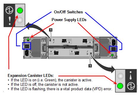
- Power off each V7000 controller by pressing the Off switches on each side of the back of the system
- Repeat the previous step to power off the second Storwize V7000 device
- Optional: Disconnect the power from the PDUs
Complete this step only if you are relocating the system to a new physical location or you are returning the system to IBM. If you are immediately restarting the system, you can omit this step and proceed to the next step.
- Locate the power breaker cabinet in the data center, and turn off the power breaker switch for the source power
- Confirm that the PDU circuit breakers are in the off position
- Disconnect the power cable from the electrical outlets
- Locate the power breaker cabinet in the data center, and turn off the power breaker switch for the source power
- Complete the following steps to restart the system:
- Power on the V7000 expansion devices by pressing the On switches located on each side of the back of the system
The power supply LEDs are displayed as solid green, which indicates the device has power.
After both of the V7000 expansion canister LEDs are displayed as solid green, which takes approximately two minutes, the devices are completely powered on.
Figure 3. V7000 expansion LEDs
- Power on each V7000 controller by pressing the On switches on each side of the system
Similar to the V7000 expansion devices, the power supply LEDs are displayed as solid green, which indicates the V7000 controller has power.
After the system status LED and status LED are both displayed as solid green, which takes approximately six minutes, the V7000 controllers are completely powered on.
Figure 4. V7000 controller LEDs
- Confirm that the bridge lights on the V7000 expansion devices are lit as shown in the following image:
Figure 5. V7000 expansion bridge light LEDs

- Power on the PureSystems Manager in bay 2 of chassis 1
Manually press the Power button on the front of the device. Press the button only once.
Figure 6. Power button for PureSystems Manager

Wait until the LED is displayed as solid green, which indicates the PureSystems Manager is completely powered on. At this point, the other management nodes and the compute nodes are then automatically powered on. The entire process takes approximately 30 minutes to complete.
- Use the workload console to start each shared service Click...
-
Instances | Shared Services | instance_name | Start
Ensure that you start the System Monitoring shared service before you start any other shared service.
- Use the workload console to start each virtual system pattern and virtual application pattern
Click...
-
Instances | pattern_instance_type | pattern_instance_name | Start
- Power on the V7000 expansion devices by pressing the On switches located on each side of the back of the system
Console icons
Use this topic as a quick reference to the icons used in the IBM PureApplication System W1500 system console and workload console.
Status icons
System console and workload console status icons
Icon Usage 
Started, Running 
Run, but health status is warning 
Run, but health status is critical 
Run, but health status is unknown 
Restart 
Stopped, Terminated 
Powered on (compute node) 
Powered off (compute node) 
Failed 
Terminating 
Pending 
In progress 
Alert 
Warning 
Major warning 
Normal 
Successful; Available; Complete; Accepted 
Informational 
Critical 
Fatal 
Unknown 
Undefined 
Service 
Quiesced 
Inactive 
Connected; Associated; Attached 
Disconnected 
Associated 
Unassociated; Unattached 
Released (IP) 
Task complete 
Task incomplete 
Certificate accepted 
Certificate expired 
Certificate not accepted 
Health warning 
Health normal 
Health critical 
Locked 
Unlocked 
Capture (virtual machine) 
Capture (virtual machine) disabled 
LED status: On normal 
On warning 
On critical 
Off 
Opened (problem opened) 
Closed (problem resolved) Action icons
System console and workload console action icons
Icon Usage 
Add; Create 
Refresh 
Start an instance 
Start an instance disabled 
Stop; Terminate an instance 
Stop disabled 
Enable 
Disable 
Delete; Remove and instance 
Manage an instance; Click the icon and a new console pane displays that includes the monitoring, logging and operations tabs. 
Manage an instance disabled 
Maintain 
Maintain disabled 
Resume (recover from maintain) 
Resume disabled 
Upgrade an instance 
Upgrade an instance disabled 
Deploy a pattern 
Deploy a pattern disabled 
Edit; Open to edit a pattern 
Import a pattern 
Import a pattern disabled 
Export a pattern 
Clone a pattern 
Extend a virtual image 
Lock a virtual image to make it read-only 
Discover hypervisors, networks and storage devices for cloud groups 
Move a hypervisor to a compute node 
Quiesce a compute node 
Power on a compute node 
Power on a compute node disabled 
Power off a compute node 
Power off a compute node disabled 
Report (machine activity) 
Restart a virtual machine 
Restart a virtual machine disabled 
Configure a virtual macine
Capture a virtual machine
Capture a virtual machine disabled 
Save 
Save as 
Organize the layout 
Search 
Search up 
Search down Resource icons
System console and workload console resource icons
Icon Usage 
CPU 
Memory 
Storage 
Disk 
Network 
Switch 
Port 
Storage volume 
Virtual machine 
Status 
LED 
Compliance 
Temperature 
Enclosure LED 
Location LED 
Event LED 
Power LED 
User (internal) 
User (internal) disabled 
User (external) 
User (external) disabled 
User group (internal) 
User group (internal) disabled 
User group (external) 
User group (external) disabled 
Additional archive file 
Enterprise application 
Existing Web service provider endpoint 
Policy set 
Web application 
Database 
DB2 
Data Studio Web console 
Existing database 
Existing IMS database 
Existing messaging service 
Queue 
Topic 
Existing OSGi bundle repository 
OSGi application 
Existing IMS TM 
Existing CICS Transaction Gateway 
Generic target 
ICCT 
Scaling policy Common icons
System console and workload console common icons
Icon Usage 
Help 
Information 
Sort 
Collapse 
Expand - Click...