Administer applications and processes in the runtime environment
After you have installed or deployed applications to the runtime environment, you need to manage them. This management includes administering the process applications or service modules themselves as well as the processes and components that are associated with them.
The tools you use depend on the type of administration task that you are doing. These topics include information on using commands, Process Admin Console, Process Center console, WebSphere Application server administrative console, Business Process Choreographer Explorer, Business Space, Process Inspector, and business rules manager.
Manage installed snapshots
Use the Process Admin Console to administer and configure runtime settings for snapshots that are installed on a process server.
When you click the Installed Apps option in the Process Admin Console, you can see the list of snapshots of process applications that have been installed on the current Process Server. Within each process application snapshot, only the processes that have been exposed are shown. For each process, you can see the number of instances currently running.
You can perform the following actions in the Installed Apps area:
- Sort and filter the list of snapshots on the server.
Click the All, Active, or Default option to filter the list of snapshots shown.
If you are using the Process Admin Console to monitor and configure the Process Center server, the list of snapshots are those of the process applications created on the current server. When you create a snapshot and save it in the Process Center repository, it is displayed as an inactive snapshot. (Click the All option to see all snapshots, including inactive ones.) If you activate a particular snapshot using the Process Center console, the snapshot is shown as active in this list.
- Configure runtime settings for a snapshot.
Click a snapshot, and then use the Exposing, Role Bindings, or Environment Vars options complete the configuration.
- Administer a snapshot.
Click a snapshot, and then select one of the options from the right margin of the Process Admin Console. The available actions vary depending on the content and current state of the installed snapshot, and include the following options. See the related links at the end of this topic for more information about performing these administration tasks.
Option Description Activate Application Activates the snapshot, which includes starting the associated business level application (BLA). Deactivate Application Deactivates the snapshot, allowing all currently running instances to complete. Deactivated snapshots remain installed, but you cannot start a new instance of the exposed processes or services. The block-deactivated-snapshot-task-progression property in 99Local.xml controls whether currently running instances in deactivated snapshots progress. When set to true, it prevents currently running instances from completing. The block-deactivated-snapshot-favorite-progression property in 99Local.xml file controls the launch and progression of taskless services associated with exposed favorites (startable services, URLs, project pages, and dashboards). When set to true, the service engine prevents these items from being launched or progressed if they are associated with deactivated snapshots. In V7.5.1.1, these properties were set to true by default. In V8.x, these properties are set to false by default.
You can delete an inactive process application snapshot on any test or production process server using the wsadmin commands. See Delete snapshots on process servers.
Stop Application Stops the snapshot and its BLA. This option is available only for deactivated snapshots that contain Advanced Integration Services. Migrate In-flight Data Migrates currently running instances to the version of the selected snapshot. Sync Settings Copies specified settings from the current snapshot to another snapshot. Make Default Version Makes the selected snapshot the default version on the current server. This option is available only when you have more than one snapshot on the server. Update Tracking Definitions If a problem occurs during snapshot installation and tracking definitions are not sent to the Performance Data Warehouse, you can use this option to send the definitions for the selected snapshot. Because tracking definitions are automatically sent to the Performance Data Warehouse during snapshot installation, you should use this option only when a problem occurs. Undeploy Application Removes the snapshot's corresponding BLA and any Advanced Integration Service artifacts from the process server,although the snapshot remains in the repository. This option is available only for stopped snapshots that contain Advanced Integration Services. To create administer a snapshot that contains IBM Business Process Manager Advanced content, the user or group to which you belong must be assigned to the Configurator, Operator and Deployer administrative security role. If you are not currently assigned to all of these roles, click Users and Groups in the WebSphere administrative console to modify the user or group roles. See "Administrative security roles" in the related links.
Activating installed process applications
Use the Process Admin Console to activate snapshots that are installed on a process server. Only the business BPD is activated when you activate a process application. If the process application uses BPEL processes and the templates were stopped (as described in Administer BPEL process and task templates), follow the instructions in that section to start the templates again.
When you activate a process application snapshot that contains an Advanced Integration service, you are actually starting the associated business level application (BLA). You can use the WAS administrative console to verify the BLA is in the expected state.
To activate a process application snapshot.
- From the Process Admin Console Installed Apps page, select the installed snapshot.
- Activate the snapshot by clicking Activate Application.
Deactivating and stopping installed process applications
Use the Process Admin Console to deactivate and, if necessary, stop snapshots that are installed on a process server. All installed snapshots except the default version can be deactivated. However, you can stop only those snapshots that contain Advanced Integration Services (such as SCA modules or BPEL processes). Deactivating a snapshot allows all existing business process definition process instances to complete, but no new process instances can be started.
Stop a process application snapshot stops the associated business level application (BLA), which exists when the snapshot contains an Advanced Integration Service. Use the WebSphere Application Server administrative console to verify the BLA is in the stopped state.
Use the Deactivate Application action from the Process Admin Console does not stop a BPEL process. Unless you are running the server in development mode or you are running the process application on a Process Center server, you might need to perform additional actions for process applications that include BPEL processes:
- If your process application uses a BPEL process as the main entry component, you must stop the corresponding BPEL template in the WebSphere administrative console. See "Administering BPEL process and task templates."
- Additionally, if this BPEL process invokes a BPD, allow any existing instances to complete after you stop the template but before you deactivate the snapshot. See "Administering BPEL process and task templates."
- In all cases, you must clean up the associated process instance data from the Business Process Choreographer database, as described in "Cleanup procedures for Business Process Choreographer."
In order to deactivate a default version of the snapshot, first designate another snapshot as the default version. (If you have only one version installed on the server, you need to create and install another snapshot and then designate that as the default version.) After the snapshot is no longer the default version, you can deactivate it.
- From the Process Admin Console Installed Apps page, select the installed snapshot.
- Deactivate the snapshot by clicking Deactivate Application .
- If the snapshot contains Advanced Integration Services, stop it by clicking Stop Application.
Designating default snapshots
On a process server, the first snapshot you install is considered the default version. This means the items within it run when an event or other trigger that applies to more than one version of a process or service is received. When you install subsequent snapshots, you can use the Make Default Version option in Process Admin Console to ensure the snapshot you want to run is the default. To designate a snapshot as the default version.
- Open the Process Admin Console and select the installed snapshot you want to use as the default.
- Click Make Default Version in the right pane of the console.
Synchronizing snapshots
Use the Process Admin Console to copy settings from one snapshot to another. You can copy the settings for environment variables, role bindings, and exposed process values. To copy settings from a selected snapshot to the current snapshot.
- Open the Process Admin Console and select the installed snapshot you want to sync.
- Click Sync Settings in the right pane of the console to open the Sync Settings - Select Snapshot to Sync From window.
- Select the snapshot from Snapshot to copy data from menu. By default, all of the settings for environment variables, role bindings, and exposed process values are copied from the selected snapshot.
- Optional: Customize the list of settings so that only those you want to copy are selected.
- Click Sync. All of the selected settings are copied from the specified snapshot to the current snapshot.
Manage orphaned tokens
An orphaned token is a pointer that is associated with an activity that was removed from a business BPD. You can use a policy file, a REST API, or Process Inspector to manage orphaned tokens.
Think of a token as an active execution step within the process. Tokens will exist on each active activity as well as for timer and message events on an active activity.
A token becomes orphaned if its associated activity is removed from a BPD of a migrated snapshot. You need to decide what to do with potential orphaned tokens or risk the process instances will not complete. For example, you have installed a new version of a process application. The new version has cleaned up a number of activities that are no longer used from the earlier version. However, there are tokens that still exist for some of these unused activities. You must either delete or move these orphaned tokens, or the migrated process instances might not be able to complete. When orphaned tokens are deleted or moved, the process instance will try to resume at the next activity that contains tokens. If a next step cannot be determined from the revised BPD, the instance will complete when there are no more active tokens. For example, if you have an activity that contains three tasks (Task A, Task B, and Task C) and Task A is currently running, it has the token. If you delete the token while Task A is running, Task B and Task C will not run, and the process instance is considered complete.
Consider another example. Again you are installing a new version of a process application. A number of explicit exception events have been removed from some of the nested processes. This removal could potentially lead to orphaned tokens when instances are migrated to the new version. It should be possible to delete (that is, to ignore) these tokens when instances are migrated from the old to the new version of the process without causing instances to hang.
The easiest way to identify and manage orphaned tokens is to generate a policy file and use it to specify whether each potential orphaned token should be moved or deleted during instance migration. If you migrate the snapshot instance without using a policy file, orphaned tokens may be created. In this case, you can use the REST API client to delete or move these orphaned tokens. You can also use the web Process Inspector to delete orphaned tokens. These methods are described in the accompanying topics.
Important considerations
Take care when making decisions about whether to delete or move tokens. Here are some of the specific cases to keep in mind while you are making those choices:
- You can move an orphaned token from one activity to another activity in the same process or subprocess.
- You can move an orphaned token from an activity in a process to an activity in any of its subprocesses.
- You can move an orphaned token from an activity in a subprocess to an activity in its parent process.
- You cannot move an orphaned token from an activity in an event subprocess to an activity outside that event subprocess.
- You cannot move an orphaned token from an activity outside an event subprocess to an activity in that event subprocess.
- You cannot move an orphaned token in a linked process to its parent process or to another linked process.
- You can only delete or move a token that is a leaf node in the execution tree; any parent orphaned tokens will be handled implicitly.
For example, suppose an activity implemented as a subprocess is deleted in a new snapshot. Deleting an orphaned token in the subprocess will also delete the orphaned token on the parent activity.
- For a parallel gateway, both branches must complete to complete the process successfully. Therefore, if you choose to delete an orphaned token on one branch of a parallel gateway, the process using the parallel gateway will never be able to complete.
- When you move a token, you are actually deleting it from one activity and creating a new copy of it attached to a different activity. This behavior creates a limitation if you are using multiple instances of nested business objects. For example, if you have an activity that has three tokens associated with it and you move those tokens to a second activity, only one token is created on the second activity.
| Source Activity Location | Target in Same Process | Target in Parent Process | Target in Child Subprocess | Target in Child Event Subprocess | Target in Child Linked Process |
|---|---|---|---|---|---|
| Process | Yes | N/A | Yes | No | No |
| Subprocess | Yes | Yes | Yes | No | No |
| Event subprocess | Yes | No | Yes | No | No |
| Linked process | Yes | No | Yes | No | No |
Manage orphaned tokens with a policy file
Use a policy file to proactively compare snapshots before instance migration to identify the potential locations of orphaned tokens and specify whether each orphaned token should be deleted or moved. This task applies to a process application snapshot that has one or more running instances. You are deploying a new version of a process. The new version has cleaned up a number of steps that are no longer used from the earlier version. However, it is possible that tokens exist on some of these unused tasks. These tokens should be mapped to existing steps in the new process so that when the you migrate the instances, the process instances do not fail. You can also delete (ignore) tokens that are no longer used in the new process.
If you use a policy file to help you with this task, follow the procedure set out here. Run the wsadmin command to get a list that you can use to spot potential migration problems so that when you migrate to the new version of the snapshot, you have some confidence that it will work. When the file is generated, it will identify all the potential orphaned tokens. Go through the file and identify how you want each token to be handled. During migration, if a policy file is specified, the migration uses that file to determine whether to delete or move orphaned tokens. If migration does not produce any orphaned tokens, the file is not used.
- Generate a policy file using the wsadmin command. Use this XML file during the migration of active process instances.
The wsadmin command compares two snapshots and produces an XML file listing all the steps in the BPD where orphaned tokens could potentially occur. The command generates an XML representation of all possible locations of orphan tokens in a policy file.
- Edit the policy file using a text editor.
- Go through the list of potential orphaned tokens and decide whether each token should be moved or deleted. By default, a delete action is specified for each token. You can change delete to move.
- When you are moving a potential orphaned token, you need to specify the target activity using the activity acronym. In Process Designer, select the target activity to which you want to move the orphaned token. From the Properties view for that activity, copy its system ID (which has a value like bpdid:b999d6be478ef107:21bb67e6:134387269e4:-7ff4)
to your clipboard. The ID is case sensitive.
- Add a move instruction to the policy file in place of the delete instruction that is there by default. Paste the token ID into the instruction. Here is an example of a simple move instruction:
<process bpdId="27d4fbbc-0175-4201-80d1-132100aca191" name="Top-level only">
    <step id="bpdid:b12b770ce3d97e30:3a0ee98f:133c7d2dc73:-7fe0" name="B">
      <move targetStepId="bpdid:b12b770ce3d97e30:3a0ee98f:133c7d2dc73:-7ff4" name="A"/>
    </step>
</process>
The policy file will not let you move a token to an invalid location. See Manage orphaned tokens for some general advice about moving potential orphaned tokens.
- Optional: You can add an attribute to suspend the process for any activity in the policy file. That attribute suspends the process instance after a token has been deleted or moved so you can edit the data before resuming the instance. To use the suspendProcess option, set the attribute to "true".
- <move targetStepId="bpdid:b12b770ce3d97e30:3a0ee98f:133c7d2dc73:-7f72" name="E1" suspendProcess="true"/>
The attribute suspendProcess="true" applies only to active instances. Inactive instances are not affected by the attribute. If an instance is already suspended, after migration using the orphaned token policy file it remains suspended.
- From the Process Admin Console, select Installed Apps.
- From the list of snapshots, select the one to which you are migrating data.
- In the Migrate Inflight Data from Snapshot window, select a snapshot to migrate from, then browse to the location of the policy file and click Migrate.
- Look at the result in the Process Inspector to ensure that all orphaned tokens have been deleted or moved or to adjust any data values after migration.
Manage tokens using the REST API Client and Process Inspector
You can use the REST API client to move or delete tokens. You can use the web Process Inspector to delete orphaned tokens, but not to move them.
- You must be a member of the tw_admins group to delete tokens using the Process Inspector in the Process Admin Console.
- The Process Portal action policies govern security permissions for token management features. The ACTION_MOVE_TOKEN, ACTION_DELETE_TOKEN, and ACTION_INJECT_TOKEN action policies must be configured to allow you to manage tokens and you must be a member of the default security group that is assigned to them to perform these actions. See restricting_access_to_portal_functions.html.
Moving tokens
Use the REST API client to move tokens.
To move a token to a new activity:
- Use the Process Inspector in the Process Admin Console to inspect the currently running process instances and select the instance containing orphaned tokens to move. Make a note of the process instance ID as well as the ID of the orphaned token, which will be shown in the execution call stack.
- Use Process Designer to identify the system ID of the activity where you want to move the orphaned token (the target activity). Record the complete value of that activity, including the "bpdid:" prefix.
- To move the token to a activity, in the REST API client, enter the following: :
/rest/bpm/wle/v1/process/instance_ID?action=moveToken&tokenId=
token_ID &target=target_step_ID[&resume=resume_value]
The following identifies the parameters of the API:
- instance_ID - the instance ID number of the process instance containing tokens to be moved
- action - states the action to be taken (moveToken)
- token_ID - the token ID number of the token you need to move
- target_step_ID - the ID number of the new process step that you are moving the token to
- resume_value - the action used to resume the instance after moving the token (set to "true" or "false"); the default value is "true"
- Press Enter to complete the move.
The system returns one of the following response codes:
- 200 = Success
- 405 = Not Authorized
- 400 = Server Error (unable to move token)
Delete tokens using the REST API client
You can use the REST API client to delete tokens.
To delete a token:
- Use the Process Inspector in the Process Admin Console to inspect the currently running process instances and select the instance containing orphaned tokens to delete. Make a note of the process instance ID as well as the ID of the orphaned token, which will be shown in the execution call stack.
- To delete the token, in the REST API client, enter the following: :
/rest/bpm/wle/v1/process/instance_ID?action=deleteToken&tokenId=
token_ID[&resume=resume_value]
The following identifies the parameters of the API:
- instance_ID - the instance ID number of the process instance containing tokens to be moved
- action - states the action to be taken (deleteToken)
- token_ID - the token ID number of the token you need to delete
- resume_value - the action used to resume the instance after deleting the token (set to "true" or "false"); the default value is "true"
- Press Enter to complete the delete action.
- On the Inspector tab of Process Designer, verify the orphan token is now deleted.
Delete tokens in Process Inspector
You can use the web Process Inspector to delete orphaned tokens.
To delete a token from a process instance:
- Open the process instance in Process Inspector.
- In the Actions panel, click Delete Orphaned Tokens.
The Actions panel shows that all orphaned tokens have been deleted.
Change the security policy
If you are upgrading from an earlier version of IBM Business Process Manager, you might need to configure the security policy before you move or delete a token.
Ensure 100Custom.xml.exists in the directory PROFILE_HOME\config\cells\cell_name\nodes\node_name\servers\server_name\process-server\config. If not, create the file. See Manage IBM Business Process Manager configuration settings with 100Custom.xml.
- Beginning in version 8.0, the security policy has been set by default to support the moving and deleting of orphaned tokens. If you are upgrading from earlier versions, you might need to configure the security policy in the following way before you can move or delete an orphaned token.
- The Process Portal action policies govern security permissions for token management features. The ACTION_MOVE_TOKEN, ACTION_DELETE_TOKEN, and ACTION_INJECT_TOKEN action policies must be configured to allow you to manage tokens and you must be a member of the default security group that is assigned to them to perform these actions. See Configuration properties for Process Portal action policies.
- Stop Process Server.
- Open the original server configuration file (99Local.xml)
and your local configuration file (100Custom.xml) in text editors.
- PROFILE_HOME\config\cells\cell_name\nodes\node_name\servers\server_name\process-server\config/system/99Local.xml
- PROFILE_HOME\config\cells\cell_name\nodes\node_name\servers\server_name\process-server\config\100Custom.xml
- In 99Local.xml, locate the following line and copy it to your 100Custom.xml file:
<portal>
<adhoc-reroute-enabled merge="replace">true</adhoc-reroute-enabled>
</portal>
- In 100Custom.xml, edit the value of the property, as shown:
<adhoc-reroute-enabled>false</adhoc-reroute-enabled>
Save 100Custom.xml and restart the server.
Migrate inflight data
Use Migrate inflight data if you have installed a new snapshot with running instances and you want to manipulate the data used by the running instances. This method enables you to manage potential orphaned tokens. It allows you to revert to a previous snapshot while you make changes to the new one.
The migration process is explained in Migrate instances. The Install Snapshot - Manage Instances window provides the option to leave the original data in place on running instances when you install a new snapshot. If you selected that option, you can use Migrate inflight data to make adjustments after installing a revised snapshot. After you install a new snapshot that replaces a snapshot with instances that are still running, you might want to migrate some data from the currently running instances to the new snapshot. In that case, use the Migrate Inflight Data window to migrate currently running instances to the new version of the selected snapshot. Wherever the running instances are in the flow of the process or service, the new version is implemented for the next step.
Only the business process definitions of the process application are migrated. If the process application contains BPEL processes, follow the instructions for migrating BPEL processes.
Use the Process Admin Console to migrate inflight data to a snapshot. To migrate inflight data.
- Open the Process Admin Console by selecting a process application in IBM Process Center and selecting Role Bindings from the resulting menu.
- From the Process Admin Console, select Installed Apps.
- From the list of snapshots, select the one to which you are migrating data.
- Click Migrate Inflight Data.
- Select the snapshot from which you want to migrate data.
- Make whatever adjustments you want to make before completing the migration. For example, you can change the value of an environmental variable. The migration program uses the latest value rather than the original value. The new value is applied to any new instances that are launched, but it is not applied to running instances. You can lessen the risk that an activity in a running instance will not complete by carefully managing tokens that are associated with actions that have been deleted. If you are using a policy file to manage potential orphaned tokens, provide the path to that policy file.
- Click Migrate.
Configure runtime settings for installed snapshots
You can use Process Admin Console to configure runtime settings for each process application snapshot that is installed on a process server, Runtime configuration settings include team bindings, exposed process and services, and environment variables.
Configuration tasks require administrative access to the Process Server on which the snapshots are installed.
To configure runtime settings, use the Installed Apps tab in the Process Admin Console. Select a snapshot, and then select the Exposing, Team Bindings, or Environment Vars option.
The Process App Settings Servers page for a process application or Toolkit Settings Servers page for a toolkit specifies the connection properties to use for accessing the following servers: Enterprise Content Management servers, IBM Case Manager Integration servers, and IBM WebSphere ILOG servers. Adding the server to the Toolkit Settings Servers page allows the connection properties to be reused.
Configure exposed processes and services
During development in Process Designer, process authors determine which processes, services, reports, and other items are available and to which participant groups. After a process application is installed on a Process Server in a different environment (test or production), you might need to disable a particular exposed item within that application.
Items that are exposed are accessible to the designated group of users. For example, users in the designated group can start an exposed process in IBM Process Portal.
Use the Process Admin Console to configure exposed processes and services for a snapshot.
- Log in to the Process Admin Console, and then click Installed Apps to show the list of current snapshots on the server.
- Click the snapshot you want to work with.
- From the top toolbar, click Exposing.
- Click the check box next to the item to disable. The item is no longer exposed to the selected group. When the exposure setting is disabled, the users within the group can no longer start or otherwise manipulate the process or service on the current server.
If you are disabling an Undercover Agent (UCA), you can determine the specific type of the UCA by observing the symbol beside the UCA name:
- A Content UCA is identified by a folder symbol.
- A Message UCA is identified by an envelope symbol.
- A Timer UCA is identified by a clock symbol.
When you disable items that are not exposed to a particular participant group, such as web services and UCAs, those items cannot be run on the current server.
Configure runtime teams
Teams can be defined statically or dynamically, and can have a team of managers that are associated with them. During development in Process Designer, process authors create the teams for each process application. After a process application is installed on a Process Server in a different environment (test or production), you might need to add or remove users and groups in those teams so the appropriate staff can access and perform the tasks that are generated by the process application.
You can modify the membership of statically defined teams and designate the managers of teams. For dynamic teams, which are defined by a team retrieval service, you can select whether the team is resolved dynamically or statically.
- Log in to the Process Admin Console, and then click Installed Apps to show the list of current snapshots on the server.
- Click the snapshot to work with.
- From the top menu bar, click Team Bindings. A list of each team and the members of each team is displayed. The teams listed are the ones that were created for the process application during process development in Process Designer.
- All teams are listed. If there are multiple instances of teams that are resolved by the same team retrieval service, the instance name is displayed in brackets after the team name. For each team listed, you can perform the following actions:
- The fields Members and Tasks show the number of members and number of task instances that are currently assigned to the team. You can use these values to help identify which teams might need more or less members.
- Click Add Users.
The Add Users window is displayed where you can enter a partial or complete user name in the Retrieve text box to display the users that are available on the current server. Select the check box for each user that you want, and click Add.
- Click Add Groups.
The Add Groups window is displayed where you can enter a partial or complete group name in the Retrieve text box to display the groups that are available on the current server. Select the check box for each group that you want, and click Add.
- To remove a user or group from a team, click the Remove icon next to an existing user or group.
- To designate the managers of a team, click the corresponding Select button, then select the appropriate team of managers.
Click the name of a managers team to scroll to that team.
- Any teams that are dynamically defined by a team retrieval service, include a Dynamic resolution enabled option that you can use to switch between dynamic and static resolution.
- When Dynamic resolution enabled is selected, which is the default, the team is resolved dynamically by the associated service, and the statically defined list of users and groups are ignored.
- When Dynamic resolution enabled is cleared, which happens when you use any of the controls to modify the static team list, the team is resolved statically.
If the Dynamic resolution enabled option is cleared and then selected again, the team resolution service is immediately called to refresh the list of team members.
Configure runtime environment variables
During development to Process Designer, process authors can set environment variables for each process application. In some cases, the correct value for a particular environment (test or production) might not be known during process design. In those cases, you need to provide the value after installing the process application to the new environment.
Use the Process Admin console to set snapshot environment variables to the appropriate values for the current server.
- Log in to the Process Admin Console, and then click Installed Apps to show the list of current snapshots on the server.
- Click the snapshot you want to work with.
- From the top toolbar, click Environment Vars.
- For the variables listed, provide a value or ensure the value shown is accurate for the current server. If no variables are listed, no variables were established during process development in Process Designer.
Configure a web service server at run time
During development in Process Designer, you can add a web service server to a process application. With time, however, the configuration values used at development time may change. For example, the policy set or policy binding may need to be changed to suit new circumstances. You can change the configuration values of a web service server at run time to accommodate these new circumstances.
Use the Process Admin console to update the configuration values of a web service server.
- Log in to the Process Admin Console. Click Installed Apps to show the list of snapshots on the server.
- Click the snapshot you want to work with.
- From the toolbar, click Servers.
The server configurations are listed alphabetically by their names.
Find the server configuration you want to update.
- Update the configuration values you want and click Apply.
The wsadmin scripting tool for managing process applications
The WebSphere administrative (wsadmin) scripting program is a powerful, non-graphical command interpreter environment that you can use to run administrative operations in a scripting language. You can use the wsadmin tool in connected mode to install, manage, and undeploy snapshots.
In a network deployment environment, an application cluster member runs the Process Server and Process Center applications. Therefore, you run these wsadmin commands on the node that contains that application cluster member. Do not run the commands from the deployment manager profile.
Not all commands can be used on both the Process Center server and process servers. Use the following table to determine which commands can be used on each type of server. Additional information about the commands and wsadmin scripting is found in the topic "Commands (wsadmin scripting)."
| Task | Command | Description | Applicable product versions |
|---|---|---|---|
| Commands for installing and undeploying snapshots (connected and offline servers) | BPMCheckOrphanTokens | Detects the possibility of orphaned tokens before you install a new snapshot; enables you to identify whether to delete or move each token.
Available for Process Center server and any running process server instance. |
BPM Standard BPM Advanced |
| BPMInstall | Installs a snapshot on a connected process server.
Available for Process Center server only. |
BPM Standard BPM Advanced | |
| BPMCreateOfflinePackage | Use this set of commands to create an installation package for a snapshot, extract it to a compressed file on a local file system, and install the package on an offline process server.
BPMCreateOfflinePackage and BPMExtractOfflinePackage are available for Process Center server only.BPMInstallOfflinePackage is available for offline process server only. |
BPM Standard BPM Advanced | |
| BPMExtractOfflinePackage |
BPM Standard BPM Advanced | ||
| BPMInstallOfflinePackage |
BPM Standard BPM Advanced | ||
| BPMDeleteSnapshot | Deletes the snapshot and any link to toolkit dependencies. This command does not delete the dependent toolkit snapshot.
Available for any running process server instance. |
BPM Standard BPM Advanced | |
| BPMUndeploy |
Removes the corresponding business level application (BLA) and related artifacts of a snapshot from the Process Center server or the process server. However, the snapshot remains in the repository. For a Process Center server, the BPMUndeploy forces an implicit stop of the snapshot before the command is completed. Available for Process Center server and any running process server instance. |
BPM Advanced | |
| Commands for viewing process applications and artifacts | BPMListProcessApplications | Lists all process application snapshots on a given server.
Available for Process Center server and any running process server instance. |
BPM Standard BPM Advanced |
| BPMShowProcessApplication | Lists information about a process application on a given server.
Available for Process Center server and any running process server instance. |
BPM Standard BPM Advanced | |
| BPMShowSnapshot | Lists information about a process application or toolkit snapshot on a given server.
Available for Process Center server and any running process server instance. |
BPM Standard BPM Advanced | |
| Commands for administering snapshots | BPMActivate | Activates a snapshot on a server.
Available for Process Center server and any running process server instance. |
BPM Standard BPM Advanced |
| BPMDeactivate | Deactivates a snapshot running on a server.
Available for Process Center server and any running process server instance. |
BPM Standard BPM Advanced | |
| BPMExport | Exports a process application snapshot to a .twx file so that it can be imported on another Process Center server.
Available for Process Center server only. |
BPM Standard BPM Advanced | |
| BPMImport | Imports a process application snapshot that has been exported from another Process Center server.
Available for Process Center server only. |
BPM Standard BPM Advanced | |
| BPMSnapshotCleanup | Deletes all the unnamed and archived snapshots of a process application on a Process Center server.
Available for Process Center server only. |
BPM Standard BPM Advanced | |
| BPMProcessInstancesCleanup | Deletes business BPD instance data for a process application snapshot
Available for any running process server instance. |
BPM Standard BPM Advanced | |
| BPMStop |
Stops the snapshot and its BLA on a process server. Available for any running process server instance. |
BPM Advanced | |
| Commands for working with servers | BPMListServers | Lists all process server instances that are federated into the Process Center server.
Available for Process Center server only. |
BPM Standard BPM Advanced |
| BPMSecurityUnlock | Unlocks an application cluster member during server startup.
Available for Process Center server and any running process server instance. |
BPM Standard BPM Advanced | |
| BPMShowServer | Lists information about a specific server.
Available for Process Center server only. |
BPM Standard BPM Advanced |
Some of the commands require administrative access; the user ID must belong to either the tw_admins or tw_authors group.
Connection types
All wsadmin commands for managing process applications must be run in connected mode and the server must be running. Use the -contype argument to indicate what connection type you want to use (SOAP or RMI). See  Use the wsadmin scripting tool in the WebSphere Application Server Information Center for detailed instructions.
Example
In the following syntax examples, myHostName.mycompany.com is the host name of the server that is configured for Process Server or for the Process Center server. Make sure to substitute your own port, host name, user name, and password when creating a connection.
In a network deployment environment, use the port configured for the application cluster member that runs the Process Server or Process Center applications. To determine the correct port number, see the WebSphere administrative console Ports collection page (click Servers > Server Types > WebSphere application servers > server_name > Communications > Ports). The values for SOAP_CONNECTOR_ADDRESS and BOOTSTRAP_ADDRESS indicate the SOAP and RMI port numbers.
- Jython example
wsadmin -conntype SOAP -port 8880 -host myHostName.mycompany.com -user admin -password admin -lang jython AdminTask.taskName('[options ]') - Jacl example
wsadmin -conntype SOAP -port 8880 -host myHostName.mycompany.com -user admin -password admin -lang jython
$AdminTask.taskName {options}
Delete snapshots on process servers
You can delete an inactive process application snapshot on any test or production process server. The process you use varies depending on whether you are using IBM Business Process Manager Advanced or IBM Business Process Manager Standard. You might want to delete snapshots and their dependencies if you no longer need them or if you have concerns about space on your system.
Before use the BPMDeleteSnapshot command, install interim fixes. See the Issues with BPMDeleteSnapshot and BPMSnapshotCleanup
commands in BPM (BPM) flash technote.
To delete snapshots to process servers, ensure you have met the following prerequisites:
- You have administrative access to the snapshot.
- The snapshot is not the default snapshot.
- There are no running instances
-
 There are no running BPEL instances.
If you need more information on how to complete these prerequisites, see the related links at the end of this topic.
Use one of the following sequences of wsadmin commands to delete a snapshot.
| Option | Description |
|---|---|
| IBM Business Process Manager Advanced |
|
| IBM Business Process Manager Standard |
|
Administer service applications and service modules
Use the administrative tools to view and manage service applications and their associated service modules.
Deploy your service modules to the runtime environment.
A service module is a Service Component Architecture (SCA) module that provides services in the runtime environment. When you deploy a service module to IBM Business Process Manager, you build an associated service application that is packaged as an Enterprise Archive (EAR) file.
Service modules are the basic units of deployment and can contain components, libraries, and staging modules used by the associated service application. Service modules have exports and, optionally, imports to define the relationships between modules and service requesters and providers. IBM Business Process Manager supports modules for business services and mediation modules. Both modules and mediation modules are types of SCA modules. A mediation module allows communication between applications by transforming the service invocation to a format understood by the target, passing the request to the target, and returning the result to the originator. A module for a business service implements the logic of a business process. However, a module can also include the same mediation logic that can be packaged in a mediation module.
Some SCA modules are associated with a process application; they provide the service integration functionality for that process application. If an SCA module is associated with a process application, do not use the administrative console to manage its state. Instead, use the Process Admin Console. The state of any SCA module in a process application is managed as part of the overall process application state within the Process Admin Console.
Resources for service modules
Service modules use resources provided by the service integration technologies of WebSphere Application Server. Service modules can also make use of a range of resources, including those provided by the Java™ Message Service (JMS) and Common Event Infrastructure. To administer the resources for service modules, you can use the WebSphere administrative console, commands, and scripting tools.
For more information about managing resources for service modules, see the related topics.
JNDI resources must not be shared across clusters. A cross-cluster module requires that each cluster have different JNDI resources. See Considerations for deploying service applications on clusters.
Service integration technologies
Service integration resources, such as bus destinations, enable a service module to use service integration technologies. Queue destinations are used by the SCA run time exploited by the service module as a robust infrastructure to support asynchronous interactions between components and modules. When you install a service module into IBM Business Process Manager, the destinations used by a module are defined on a member of the SCA.SYSTEM bus. These bus destinations are used to hold messages that are being processed for components of the service module that use asynchronous interactions:
- Queue sca/module_name
- This is the destination used to buffer asynchronous requests sent to module module_name
- Queue sca/module_name/exportlink/export_name
- This is the destination used by the export to send asynchronous requests to the module. Requests are routed to the component target linked to the export.
- Queue sca/module_name/importlink/import_name
- This is the destination used by the import to send asynchronous requests out of the module. Requests are routed to the module export linked to the import.
- Queue sca/module_name/import/sca/dynamic/import/scaimport [for SCA binding]
- Queue sca/module_name/import/sca/dynamic/import/wsimport [for Web service binding]
- Queue sca/contextStore/module_name
For each of the destinations, a queue point is also created and defined on the messaging engine of the relevant bus member.
You can deploy and use service modules without needing to manage these resources. However, you might want to adjust the configuration of the resources ( to modify the maximum messaging quality of service used) or to use them in locating messages for troubleshooting.
Java Message Service (JMS)
JMS resources enable a service module to use asynchronous messaging as a method of communication based on the Java Message Service (JMS) programming interface. The JMS support used depends on the JMS binding of the module. For example, a module with a JMS binding uses a JMS connection factory configured on the default messaging provider provided by the underlying WebSphere Application Server, while a module with a WebSphere MQ JMS binding uses a JMS connection factory configured on WebSphere MQ as the JMS provider. To manage use of the Java Message Service, you can administer the following resources:
- JMS connection factory
- A JMS connection factory is used to create connections to the associated JMS provider of JMS destinations, for both point-to-point and publish/subscribe messaging. Use connection factory administrative objects to manage JMS connection factories for the provider.
- JMS queue
- A JMS queue is used as a destination for point-to-point messaging. Use JMS queue destination administrative objects to manage JMS queues for the provider.
- JMS topic
- A JMS topic is used as a destination for publish/subscribe messaging. Use topic destination administrative objects to manage JMS topics for the provider.
- JMS activation specification
- A JMS activation specification is associated with one or more message-driven beans and provides the configuration necessary for them to receive messages.
- JMS listener port
- A JMS listener port defines the association between a connection factory, a destination, and a message-driven bean. This enables deployed message-driven beans associated with the port to retrieve messages from the destination.
Common Event Infrastructure (CEI)
CEI resources enable a service module to use standard formats and mechanisms for managing event data. To manage use of the Common Event Infrastructure, you can administer the following resources:
- Data Store Profile
- This profile defines properties used by the default data store. The default data store is the data store supplied by the Common Event Infrastructure.
- Emitter Factory Profile
- This profile defines the options for an event emitter.
- Event Bus Transmission Profile
- This profile defines the EJB entry into the event bus.
- Event Group Profile
- This profile defines a list of events which are determined through selector expressions. JMS queues and a JMS topic can be associated with each event group. If the event server distribution service is enabled and an event matches an event group the event is distributed to any topic or queues configured for that particular event group.
- Event Server Profile
- This profile defines the properties for the event server.
- Filter Factory Profile
- This profile defines the properties of a filter. The filter uses the filter configuration string to determine whether an event will be passed to the bus.
- JMS Transmission Profile
- This profile defines a JMS queue entry into the event bus. It defines the JNDI names for a JMS queue and queue connection factory.
Versioning in service applications
Service applications support versioning. You can develop and deploy one or more versions of a module and its artifacts into the runtime environment for use by specific clients.
This topic describes how versioning works in a service application deployed directly from IBM Integration Designer. See the related links for information on the versioning of process applications deployed from the repository in Process Center.
What can be versioned?
A module can have a version number, as can the SCA import and export bindings in a module. SCA bindings inherit their version information from the module they are associated with.
At this time, SCA bindings are the only binding type that can be versioned. Versioning is optional for modules. Modules developed and deployed with versions of Integration Designer (previously WebSphere Integration Developer) and WebSphere Enterprise Service Bus before 7.0 do not have versions and continue to function with their current behavior. Refer to the migration topics for more information.
Libraries can also be versioned. Modules that use a library have a dependency on a specific version of that library, and libraries can also have dependencies on specific versions of other libraries.
Considerations for deploying versioned modules
You can deploy a versioned module into the runtime environment and administer it from the SCA modules pages within the WebSphere Application Server administrative console. IBM Business Process Manager supports the following versioned deployment scenarios:
- Install a versioned module to a server or cluster in a cell
- Install the same version of a module once to each of one or more servers or clusters in a cell
- Install different versions of a module on the same server or cluster
Deploy a new version of a module does not replace any previous versions of the module. Previous versions of cell-scoped application artifacts are overwritten.
To update an application ( to make minor corrections or improvements) without changing the version, that updated application and its artifacts will replace the existing application and artifacts, with the exception of any defined security policies. All security policy artifacts are preserved during an application update.
To preserve versioning information, the installation process automatically changes the module name (by way of the serviceDeploy or createVersionedSCAModule command) to ensure it is unique within the cell. This change is accomplished by adding the version number, a unique cell ID, or both to the original module name.
- moduleName_vversionValue_uniqueCellID
Considerations for binding versioned modules
After you have deployed multiple versions of a module on a server or multiple instances of a module across clusters, consider how to bind specific versions of modules to clients (which might or might not be versioned).
- Static binding: If you are using static binding, use the existing administrative tools to bind a versioned module to a client. Set the module version number in the static binding.
- Dynamic binding: To use dynamic binding with versioned modules, use a mediation flow component that contains the module version metadata (versionValue and versionProvider) and service-version-aware routing. Note that in order to use service-version-aware routing to dynamically bind versioned modules, all modules must be registered with WebSphere Service Registry and Repository (WSRR).
Administer service modules with the administrative console or widgets
Use the administrative console and administration widgets to view and modify service modules. You can do some tasks, such as viewing modules and their properties, in both administrative interfaces. Other tasks, such as stopping and starting modules or modifying business calendars, are specific to one interface.
Module administration with the administrative console
After deploying service applications, use the administrative console perform the following types of tasks:
- List all of the associated service modules deployed to Process Server, including mediation modules
- See the applications associated with each module, and determine if those applications are running
- List details for a service module, including module properties
- List details about the application used to deploy a service module
- Start or stop a service module
- Modify service module properties
- Work with imports and exports for a service module
For specific information on these tasks, refer to the online help in the administrative console.
Module administration with widgets
Use one or more of the administration widgets in a business space to browse deployed modules in a cell, view detailed information about each module, and edit module artifacts. These artifacts can include module properties, business rule groups, security roles, business calendars, and service control points.
For example, the Module Browser widget has a graphical view that visually represents the services exposed and invoked by a module with appropriate contextual information about each. Detailed information about the module is also available and includes the module version, cell identifier (used to uniquely identify a versioned module in a cell), and endpoints. The graphical view provides overall module status and highlights any existing configuration problems.
The Module Browser widget is used with other administration widgets. It enables you to list the names of any properties and policies defined for the module. In addition, if you are using Process Server, it lists the business rules, BPEL processes, business state machines, human tasks, business calendars, and security roles defined for the module. Select an artifact from the list in this widget to perform any necessary administration tasks in related widgets.
As a group, these widgets provide visibility into all the administrative artifacts in an application cluster, effectively aggregating solution administration. The data provided in these widgets can help you answer questions such as these:
- What services are consumed in or exposed by a module?
- Is the module wiring correct, and are the correct versions of modules deployed?
- Are all service exports and service imports bound to existing modules?
- What is the status of a module? Is it running, or stopped?
- Are there any failed events in the module?
- What properties does the module expose?
- What mediation policies are associated with the module?
- What BPEL processes and human tasks are used in a module?
- What security roles are used in a module?
- What business calendars are used in a module?
- What business state machines are defined for a module?
- What business rules are used in a module?
For detailed task information, refer to the online help provided with each widget.
Use commands to manage service applications
You can manage service applications using commands. The commands can be used within scripts.
Use the wsadmin tool to run service application commands. You can use the wsadmin tool in different ways. You can use the tool interactively, as an individual command, or with a script. Running multiple commands in a script is useful if you are administering multiple machines.
IBM Business Process Manager includes commands that display SCA modules and their imports and exports and that change the details of import and export binding. For example, you can use the listSCAModules, showSCAModuleProperties, and modifySCAModuleProperty to examine and modify SCA modules. To examine the import and export bindings for a module, use thelistSCAImports, listSCAExports, showSCAImport, and showSCAExport commands. To modify an import or export binding, use the appropriate wsadmin command for your binding type ( modifySCAImportJMSBinding or modifySCAExportHttpBinding).
Administer the throughput of SCA requests
For each Service Component Architecture (SCA) module deployed, requests being processed are held on queue points and in the data store for messaging engines. You can display the data for SCA requests, and take any appropriate action to manage the throughput of SCA requests. When an SCA module is running, requests normally flow through the enterprise service bus without needing to be managed. Sometimes, you might want to check the throughput of a request, check the contents of a request, or if some problem has occurred, delete a request. You might also want to take other actions such as to monitor the overall throughput of requests, or change the reliability setting for requests.


Requests are handled as messages by the service integration technologies of the underlying WebSphere Application Server. For this reason, actions to manage requests are managed by using the WebSphere Application Server tasks to act on service integration messages.
This topic provides an overview of the main tasks that you might consider using, and links into the WebSphere Application Server tasks for more detailed information.
Manage service integration in applications
This set of topics provides information about the service integration technologies. Service integration is implemented as a group of messaging engines running in application servers (usually one engine to one server) in a cell.
A service integration bus is a form of managed communication that supports service integration through synchronous and asynchronous messaging. A bus consists of interconnecting messaging engines that manage bus resources. The members of a service integration bus are the application servers and clusters on which the messaging engines are defined.
Service Integration Bus Browser
The Service Integration Bus Browser available in the administrative console provides a single location for browsing and performing day-to-day operational tasks on service integration buses.
Each deployment environment has its own bus. The single bus is called BPM.env_name.Bus. Examples of day-to-day operations include browsing service integration buses, viewing runtime properties for messaging engines, or managing messages on message points. The browser is not intended as a bus configuration tool.
When you access the Service Integration Bus Browser by clicking Service Integration > Service Integration Bus Browser in the administrative console, two panes open to the right of the standard console navigation pane:
- Navigation tree pane
- This pane contains a navigation tree that allows you to browse the service integration buses configured on the system.
- Content pane
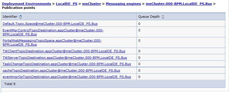
- This pane contains collection and detail pages for the buses and their individual components, such as messaging engines, queue points, destinations, publication points, and mediation points.
Note that not all pages can be edited when accessed from a link in the navigation tree. See the online help for the browser for more detail, including how to access versions of the page that can be edited.

Table 1 lists and describes the icons associated with each item in the navigation tree.
| Icon | Description |
|---|---|
|
| Indicates a collection of buses, destinations, queue points, publication points, or mediation points, depending on where in the navigation tree it appears. |
|
| Indicates a service integration bus. |
|
| Indicates a messaging engine. |
|
| Indicates a service integration bus member. |


Work with targets
Targets provide additional flexibility by allowing you to modify processing by changing the target configured for a reference.
A component can call a component in another module to minimize the time and cost of building an application. Targets provide additional flexibility: to allow your installed applications to benefit from advances in processing or other changes, you can use the administrative console to change the endpoint of a cross-module invocation, without rewriting or redeploying the application.
To take advantage of the flexibility provided, you must understand how the system names the targets. The link from the calling module must connect to the correct target.
Target names
Target names are derived from how the calling component invokes the target. The names have the following format:
- Invocation type
- Name format
- Synchronous
- A name that follows the Java™ Naming and Directory Interface (JNDI) format, for example:
- folder/export/fullpath_to_target/target_component_name
- Asynchronous
- A name with the format
folder/calling_component_name/
full_path_to_target_component/target_component_name
- Multiple destinations
- This name is the same as an asynchronous invocation but the target sends a message to multiple destination components.
Change import targets
Change the target of a reference provides applications with the flexibility of taking advantage of advances in components as they happen without recompiling and reinstalling the application.
Before changing the target for a reference you must:
- Verify the new target uses the same data object type
- Know whether the module is synchronously or asynchronously invoking the target
- Know whether the reference targets a single or multiple services
Change the target of an import from a module when another service with the same interface as the original target provides new or improved functionality that your module can use.
- Stop the module that contains the reference that you are changing.
- Use the administrative console, display the Service Component Architecture (SCA) modules.
Navigate to this panel using Applications > SCA Modules
- Select your module and press Stop. The display updates to show the application as stopped.
- Use the administrative console, display the Service Component Architecture (SCA) modules.
- Change the target destination of the reference.
How you make the change depends on how the module invokes the target.
Type of invocation How to change Single target service - Use the administrative console, display the SCA Modules. Navigate to the panel using Applications > SCA Modules.
- From the displayed list, select the module that contains the import that references the target to change.
- Expand the list of imports by clicking the plus sign (+) next to Imports.
- Select the import to change from the list.
- In the Target area, select the Module from the list.
- After the Export list refreshes, select the export for the new target.
Save the change by clicking OK.
Multiple target services - Display the buses on the system on which the module resides. Navigate to the panel using Service Integration > Buses.
- Select the SCA.System.cellname.Bus
- Display the destination targets for the bus by clicking Destinations.
- Select the destination that represents the import that connects the calling module to the targets. This identifier will contain the word import.
- Display the list of properties by clicking Context properties.
- Select the property to change by clicking on the targets property in the list.
- Change the Context value field to the new destination targets.
- Return to the Context properties panel
by clicking OK.
Save the change by clicking OK.
Save changes. Click Save when prompted.
- Use the administrative console, display the SCA Modules. Navigate to the panel using Applications > SCA Modules.
Start the module and make sure the module receives the expected results.
Work with imports and exports
You can list the imports and exports of service modules that have been deployed to IBM Business Process Manager. You can also display import and export interfaces and change the details of import bindings and selected export bindings.
Displaying an import or export interface
You can display the import or export interfaces of service modules that have been deployed to IBM Business Process Manager.
To display the import or export interfaces of service modules that you have deployed, use the administrative console to complete the following steps.
- From the console navigation pane, click Applications > SCA Modules > moduleName to display the SCA Modules detail page for that module.
- From the SCA Modules detail page, do one of the following tasks, depending on the type of interface you want to view.
Option Description View an import interface - In the content pane, expand Imports to list all imports associated with the module.
- Expand the import you want to view, and then expand Interfaces to display the import interfaces.
- Select the interface you want to display.
View an export interface - In the content pane, expand Exports to list all exports associated with the module.
- Expand the export you want to view, and then expand Interfaces to display the export interfaces.
- Select the interface you want to display.
- In the content pane, expand Imports to list all imports associated with the module.
The content pane displays the WSDL (Web Services Description Language) interface.
Displaying an import or export binding
You can display details about import and export bindings after you deploy service modules to IBM Business Process Manager.
To display the import or export binding details of service modules that you have deployed, use the administrative console to complete the following steps.
- From the console navigation pane, click Applications > SCA Modules > moduleName to display the SCA Modules detail page for that module.
- From the SCA Modules detail page, do one of the following tasks, depending on the type of binding you want to view.
Option Description View an import binding - In the content pane, expand Imports to list all imports associated with the module.
- Expand the import you want to view, and then expand Bindings to display the import bindings.
- Select the binding you want to display.
View an export binding - In the content pane, expand Exports to list all exports associated with the module.
- Expand the export you want to view, and then expand Bindings to display the export bindings.
- Select the binding you want to display.
- In the content pane, expand Imports to list all imports associated with the module.
The content pane displays the import or export binding details.
Administer bindings
You can display information about import and export bindings and, in some cases, you can update the properties of the bindings. You use the administrative console to display and change information related to bindings. You can also use commands to show and modify import and export binding information.
Administer SCA bindings
You can view information about the SCA import and export bindings of a module after the module has been deployed to the server. You can also reconfigure selected properties of an SCA import binding.
View and updating SCA import bindings
Use the administrative console, you can view information about a Service Component Architecture (SCA) import binding and change the target of the associated module.
To perform this task, you must have permission to change the master configuration. To view information about an SCA import binding or to change the target of the associated module, use the administrative console to complete the following steps.
- Select the module that contains the binding by navigating to Applications > SCA Modules and clicking the module name.
- Select the binding by performing the following steps:
- In the Module components section, expand Imports.
- Expand the import, and then expand Binding.
- Click the binding to view information about its properties.
- Module identifies the module that contains the import with this import binding.
- Version displays the SCA module version, if the module is versioned.
- Cell ID identifies the SCA module instance in the cell.
- Import identifies the import that contains the selected import binding.
- Import interfaces contains the list of interfaces for the import of this module.
- In the Module components section, expand Imports.
- To select a new target SCA module.
- Select a module from the Target list.
Selecting another SCA module changes the exports and export interfaces that are displayed.
- Select an export from the Export list.
Save changes to the master configuration.
- Select a module from the Target list.
If you made any updates, the binding is changed for the selected module. The changes take effect after you restart the SCA module.
If the module is redeployed, the configuration changes you made are replaced by the original settings.
To ensure the changes you made remain with the module across deployments, use IBM Integration Designer to make the changes in the source code for the module.
View SCA export bindings
Use the administrative console, you can view information about a Service Component Architecture (SCA) export binding, such as the name of the associated module and the name of the Web Services Description Language (WSDL) file. To view information about an SCA export binding, use the administrative console to complete the following steps.
- Select the module that contains the binding by navigating to Applications > SCA Modules and clicking the module name.
- Select the binding by performing the following steps:
- In the Module components section, expand Exports.
- Expand the export, and then expand Binding.
- Click the binding to view information about its properties.
- Module identifies the module that contains the export with this export binding.
- Version displays the SCA module version, if the module is versioned.
- Cell ID identifies the SCA module instance in the cell.
- Export identifies the export that contains the selected export binding.
- Export interfaces contains the list of interfaces for the export of this module.
- In the Module components section, expand Exports.
Administer web service bindings
You can view information about the web service import and export bindings of a module after the module has been deployed to the server. You can also reconfigure selected properties of import bindings and configure policy sets for the bindings.
View and updating Web service import bindings
Use the administrative console, you can view information about a web service import binding and change the endpoint URL. For the Java™ API for XML Web Services (JAX-WS) bindings, you can also configure a policy set for the binding.
To perform this task, you must have permission to change the master configuration. The steps for administering web service bindings depend on the type of binding:
- For JAX-RPC
bindings, you can view attributes of the binding and edit the target endpoint.
- For JAX-WS bindings, you can view attributes of the binding, edit the target endpoint, and configure policy sets.
A policy set is a collection of policy types, each of which provides a quality of service. These types have been configured and can be associated with a web service provider or consumer.
Policy sets work in pairs. You must have the same policy set on the service requester as on the service provider. Therefore, you should have the same policy set on the import binding as on the service provider it is calling.
The Policy set attachments section of the administrative console page appears only for JAX-WS bindings. It does not appear for JAX-RPC service bindings.
- Select the module that contains the binding by navigating to Applications > SCA Modules and clicking the module name.
- Select the binding by performing the following steps:
- In the Module components section, expand Imports.
- Expand the import, and then expand Binding.
- Click the binding to view information about its properties.
- In the Module components section, expand Imports.
- Change the value of Target endpoint address, which is the location of the web service, and then click Apply or OK.
- For JAX-WS bindings only, configure policy sets for import bindings by performing the following tasks:
- Optional: Expand Preferences, indicate the maximum number of rows and whether you want to retain the filter criteria, and click Apply.
- Optional: Select the filter icon to use a filter to search the table.
- Select the import binding, and click Attach to attach a policy set to the binding, or click Detach to remove the policy set.
- To assign a policy set binding, select the import binding, click Assign Binding, and provide a name for the policy set binding.
- Repeat steps 4.c and 4.d for each binding you want to configure.
Save changes to the master configuration.
If you made any updates, the binding is changed for the selected module. The changes take effect after you restart the SCA module.
If the module is redeployed, the configuration changes you made are replaced by the original settings.
To ensure the changes you made remain with the module across deployments, use IBM Integration Designer to make the changes in the source code for the module.
View and updating web service export bindings
Use the administrative console, you can view information about a web service export binding (including the WSDL file) and configure properties of the associated web module. For the Java™ API for XML Web Services (JAX-WS) bindings, you can also configure a policy set for the binding.
To perform this task, you must have permission to change the master configuration. The steps for administering web service bindings depend on the type of binding:
- For JAX-RPC bindings, you can view attributes of the binding.
- For JAX-WS bindings, you can view attributes of the binding and configure policy sets.
A policy set is a collection of policy types, each of which provides a quality of service. These types have been configured and can be associated with a web service provider or consumer.
Policy sets work in pairs. You must have the same policy set on the service requester as on the service provider. Therefore, you should have the same policy set on the export binding as on the client.
The Policy set attachments section of the administrative console page appears only for JAX-WS bindings. It does not appear for JAX-RPC service bindings.
- Select the module that contains the binding by navigating to Applications > SCA Modules and clicking the module name.
- Select the binding by performing the following steps:
- In the Module components section, expand Exports.
- Expand the export, and then expand Binding.
- Click the binding to view information about its properties.
- In the General Properties section, view the name, port, and location (endpoint address) of the web service.
- From the Related Properties list, click the interface to view the Web Services Description Language (WSDL) file that is associated with the web service.
- In the General Properties section, view the name, port, and location (endpoint address) of the web service.
- In the Module components section, expand Exports.
- To change properties that are associated with the web module, click one of the following properties in the Web Module Properties list:
- Click Manage Export Binding Web Module to view or edit deployment-specific information for a web module. For example, you can edit the Starting weight, which specifies the priority of this module during server startup.
- Click Context Root to view the web module name and Uniform Resource Identifier (URI) and edit the context root.
- Click Virtual Hosts to specify the virtual host for the web module. Virtual hosts let you associate a unique port with a module or application.
- Click JSP reload options for Web modules to specify information about the reloading of JavaServer Pages (JSP) files (such as the number of seconds to scan a file system for updated JSP files).
- Click Session management to specify information about HTTP session support. For example, you can set the number of minutes before a session times out.
- For JAX-WS bindings only, configure policy sets for export bindings by performing the following tasks:
- Optional: Expand Preferences, indicate the maximum number of rows and whether you want to retain the filter criteria, and click Apply.
- Optional: Select the filter icon to use a filter to search the table.
- Select the export binding, and click Attach to attach a policy set to the binding, or click Detach to remove the policy set.
- To assign a policy set binding, select the export binding, click Assign Binding, and provide a name for the policy set binding.
- Repeat steps 4.c and 4.d for each binding you want to configure.
Save the changes to the master configuration.
If you made any updates, the binding is changed for the selected module. The changes take effect after you restart the SCA module.
If the module is redeployed, the configuration changes you made are replaced by the original settings.
To ensure the changes you made remain with the module across deployments, use IBM Integration Designer to make the changes in the source code for the module.
Work with web service (JAX-WS) bindings
When you use web service (JAX-WS) bindings with applications, you can add a SAML quality of service (QOS) to the binding. You must first use the administrative console to import the policy set. You can also use the administrative console to make sure the server is properly configured for use with the web service (JAX-WS) binding.
Import SAML policy sets
SAML is an XML-based OASIS standard for exchanging user identity and security attributes information. When you configure a web service (JAX-WS) binding in Integration Designer, you can specify an SAML policy set. You first use the administrative console of IBM Business Process Manager to make the SAML policy sets available so they can be imported into Integration Designer.
The SAML policy sets are typically located in the profile configuration directory:
profile_root/config/templates/PolicySets
Before you begin this procedure, verify the following directories (which contain the policy sets) are located in the profile configuration directory:
- SAML11 Bearer WSHTTPS default
- SAML20 Bearer WSHTTPS default
- SAML11 Bearer WSSecurity default
- SAML20 Bearer WSSecurity default
- SAML11 HoK Public WSSecurity default
- SAML20 HoK Public WSSecurity default
- SAML11 HoK Symmetric WSSecurity default
- SAML20 HoK Symmetric WSSecurity default
- Username WSHTTPS default
If the directories are not in the profile configuration directory, copy them to that directory from the following location:
app_server_root/profileTemplates/default/documents/config/templates/PolicySets You import the policy sets into the administrative console, select the ones you want to make available to Integration Designer, and then save a .zip file for each of those policy sets to a location accessible by Integration Designer.
- Import the policy sets by following these steps:
- From the administrative console, click Services > Policy Sets > Application policy sets.
- Click Import > From Default Repository.
- Select the SAML default policy sets, and click OK.
- Export the policy sets so they can be used by Integration Designer:
- From the Application policy sets page, select the SAML policy set you want to export, and click Export.
If the Application policy sets page is not currently displayed, click Services > Policy Sets > Application Policy Sets from the administrative console.
- On the next page, click the .zip file link for the policy set.
- In the File Download window, click Save and indicate a location accessible by Integration Designer.
- Click Back.
- Complete steps 2.a through 2.d for each policy set you want to export.
- From the Application policy sets page, select the SAML policy set you want to export, and click Export.
The SAML policy sets are saved in .zip files and are ready to be imported into Integration Designer.
Import the policy sets into Integration Designer, as described in the topic "Policy sets".
Invoking web services that require HTTP basic authentication
HTTP basic authentication employs a user name and password to authenticate a service client to a secure endpoint. You can set up HTTP basic authentication when sending or receiving web service requests.
You set up HTTP basic authentication for receiving web service requests by configuring the JAX-WS export binding, as described in the Create and assigning security roles to web service exports.
HTTP basic authentication can be enabled for web service requests that are sent by a JAX-WS import binding in one of two ways:
- When configuring the import binding in an SCA module, you can select the supplied HTTP authentication policy set named BPMHTTPBasicAuthentication (which is provided with the web service (JAX-WS) import binding) or any other policy set that includes the HTTPTransport policy.
- When constructing the SCA module, you can use mediation flow capabilities to dynamically create a new HTTP authentication header and specify the user name and password information in the header.
The policy set has precedence over the value specified in the header. To use the value set in the HTTP authentication header at run time, do not attach a policy set that includes the HTTPTransport policy. Specifically, do not use the default BPMHTTPBasicAuthentication policy set, and, if you have defined a policy set, make sure it excludes the HTTPTransport policy.
For more information about web service policy sets and policy bindings and how they are used, see Web services policy sets of the WAS Information Center.
- To use the supplied policy set.
- Optional: In the administrative console, create a client general policy binding or edit an existing one that includes the HTTPTransport policy with the required user ID and password values.
- In IBM Integration Designer, generate a web service (JAX-WS) import binding and attach the BPMHTTPBasicAuthentication policy set.
- Perform one of the following steps:
- In IBM Integration Designer, in the web service (JAX-WS) import binding properties, specify the name of an existing client general policy binding that includes the HTTPTransport policy.
- After deploying the SCA module, use the administrative console to either select an existing client policy binding, or create a new client policy binding and then associate it with the import binding.
- In IBM Integration Designer, in the web service (JAX-WS) import binding properties, specify the name of an existing client general policy binding that includes the HTTPTransport policy.
- Optional: In the administrative console of the process server, edit the selected policy set binding to specify the required ID and password.
- To specify the user name and password in the HTTP authentication header, perform one of the following sets of steps:
- Use the HTTP Header Setter mediation primitive in IBM Integration Designer to create the HTTP authentication header, and specify the user name and password.
- If additional logic is required, use Java code in a custom mediation primitive (as shown in the following example) to:
- Create an HTTP authentication header.
- Set the user name and password information.
- Add the new HTTP authentication header to HTTPControl.
- Set the updated HTTPControl back in the Context service.
       //Get the HeaderInfoType from contextService         ContextService contextService = (ContextService) ServiceManager.INSTANCE
        .locateService("com/ibm/bpm/context/ContextService");
        HeaderInfoType headers = contextService.getHeaderInfo();
       if(headers == null){
            headers = ContextObjectFactory.eINSTANCE.createHeaderInfoType();
        }
        //Get the HTTP header and HTTP Control from HeaderInfoType
        HTTPHeaderType httpHeaderType = headers.getHTTPHeader();
        HTTPControl cp = httpHeaderType.getControl();
        HeadersFactory factory = HeadersFactory.eINSTANCE;
       if(cp == null){
            cp = factory.createHTTPControl();
        }
        //Create new HTTPAuthentication and set the HTTPCredentials
        HTTPAuthentication authorization = factory.createHTTPAuthentication();
        HTTPCredentials credentials = factory.createHTTPCredentials();
        authorization.setAuthenticationType(HTTPAuthenticationType.BASIC_LITERAL);
        credentials.setUserId("USERNAME");
        credentials.setPassword("PASSWORD");
        authorization.setCredentials(credentials);
        cp.setAuthentication(authorization);
        httpHeaderType.setControl(cp);
        // Set header info back to the current execution context.
        contextService.setHeaderInfo(headers);
Checking the server configuration
When you deploy an application with a web service (JAX-WS) binding, you must make sure the server on which the application is deployed does not have the Start components as needed option selected. You can check to see whether this option is selected by performing the following steps from the administrative console:
- Click Servers > Server types > WebSphere application servers.
- Click the server name.
- From the Configuration tab, determine whether Start components as needed is selected.
- Perform one of the following steps:
- If Start components as needed is selected, remove the check, and then click Apply.
- If Start components as needed is not selected, click Cancel.
Administer HTTP bindings
You can view information about the HTTP import and export bindings of a module after the module has been deployed to the server. You can also tune, or set, special features of the import and export bindings.
You use Integration Designer to create HTTP imports and exports.
View and updating HTTP import bindings
Use the administrative console, you can change the configuration of HTTP import bindings without changing the original source and then redeploying the application.
Change HTTP import bindings when the binding properties of an HTTP application used by a Service Component Architecture (SCA) module change.
When security and role-base authorization are enabled, you must log in as an administrator or configurator to perform this task.
- Select the module that contains the binding by navigating to Applications > SCA Modules and clicking the module name.
- Select the binding by performing the following steps:
- In the Module components section, expand Imports.
- Expand the import, and then expand Binding.
- Click the binding to view information about its properties.
- In the Module components section, expand Imports.
- Select the scope for the changes you want to make.
- To change the configuration on the binding scope, click the Binding Scope tab.
- To change the configuration at the method scope, click the Method Scope tab.
When both configurations exist, the method scope configuration takes precedence over the binding scope configuration.
- Make changes to one or more of the following properties:
- Select method (Method scope only)
Choose the method to review or configure. Click the arrow in the Select method field to see the list of methods that can be configured.
- Endpoint URL
Specifies the URL for the target service.
- HTTP Method
Specifies the method to use for the endpoint URL.
- HTTP version
Specifies the HTTP version to use for this endpoint URL. The choices are 1.0 and 1.1. The default is 1.1.
- Number of connection retries
Specifies the number of times the request is retried when the system receives an error response. The default is 0, which means that, after a failure, no attempt is made.
- Basic HTTP authentication
Specifies the authentication alias to use with the HTTP server on this binding.
To choose the authentication alias, select the alias name from the list. To change the attributes of a selected authentication alias, click Edit. To create a new authentication alias, click New.
- SSL authentication
Specifies the SSL configuration to use for this binding.
To edit an existing configuration, select the name from the list and click Edit. To create a new configuration, click New.
- Transfer Encoding
Specifies how information is transferred between the endpoints. Choices are chunked or identity.
The chunked encoding modifies the body of a message in order to transfer it as a series of chunks, each with its own size. This allows dynamically produced content to be transferred along with the information necessary for the recipient to verify that it has received the full message.
If you set this parameter to chunked, Content Encoding is set to identity and you will be unable to change Content Encoding.
- Content Encoding
Specifies how the content that traverses the binding is encoded. Choose either gzip, x-gzip, deflate, or identity.
- HTTP proxy settings or HTTPS proxy settings
Specifies the settings for bindings that do not require security authorization for access (HTTP proxy settings) or that do require authorization for access (HTTPS proxy settings).
- Proxy host
Specifies the host name or IP address of an HTTP proxy server through which to connect to the endpoint URL.
- Proxy port
Specifies the port used to connect to an HTTP proxy server for this binding.
- Proxy credentials
Specifies the Java2 Connectivity (J2C) authentication alias to use for the proxy settings.
To change an existing alias, select the alias from the list and click Edit. To add a new alias, click New.
- Non-proxied hosts
Specifies a list of hosts on this binding that do not use proxies. Enter each host on a separate line (use the Enter key).
To add a host to the list, type the host at the end of the list, separating it from the previous entry by clicking the Enter key. To remove a host from the list, delete the host from the list.
- Proxy host
- Response read timeout
Specifies the time, in seconds, the binding waits to read the response message from the HTTP transport channel. Setting this field to 0 causes the binding to wait indefinitely.
The HTTP transport channel has its own Read timeout value, which is the amount of time the channel waits for a read request to complete on a socket after the first read request occurs. This setting is described in
HTTP transport channel settings in the WebSphere Application Server Information Center.
Save changes to the master configuration.
- Select method (Method scope only)
If you made any updates, the binding is changed for the selected module. The changes take effect after you restart the SCA module.
If the module is redeployed, the configuration changes you made are replaced by the original settings.
To ensure the changes you made remain with the module across deployments, use IBM Integration Designer to make the changes in the source code for the module.
View and updating HTTP export bindings
Use the administrative console, you can change the configuration of HTTP export bindings without changing the original source and then redeploying the application.
Change HTTP export bindings when you need to change whether a method on a binding is pingable or to change the encodings a method or binding supports.
When security and role-base authorization are enabled, you must log in as an administrator or configurator to perform this task.
- Select the module that contains the binding by navigating to Applications > SCA Modules and clicking the module name.
- Select the binding by performing the following steps:
- In the Module components section, expand Exports.
- Expand the export, and then expand Binding.
- Click the binding to view information about its properties.
- In the Module components section, expand Exports.
- Select the scope for the changes you want to make.
- To change the configuration on the binding scope, click the Binding Scope tab.
- To change the configuration at the method scope, click the Method Scope tab.
When both configurations exist, the method scope configuration takes precedence over the binding scope configuration.
- Make changes to one or more of the following properties:
- Select method (Method
scope only)
Choose the method to review or configure. Click the arrow in the Select method field to see the list of methods that can be configured.
- HTTP Methods
Lists the methods and the current configuration for the methods. You can set whether the method is pingable and the return code for the method.
- Method
The name of the method. The methods are GET, POST, PUT, DELETE, TRACE, OPTIONS, and HEAD.
- Pingable
Whether or not an HTTP client can ping the method. When selected, you must specify the return code the binding returns to the client. The default for this is unchecked.
- Return code
An integer returned when an HTTP client pings the method.
- Method
- Transfer Encoding
Specifies how information is transferred between the endpoints. Choices are chunked or identity.
The chunked encoding modifies the body of a message in order to transfer it as a series of chunks, each with its own size. This allows dynamically produced content to be transferred along with the information necessary for the recipient to verify that it has received the full message.
If you set this parameter to chunked, Content Encoding is set to identity and you will be unable to change Content Encoding.
- Content Encoding
Specifies how the content that traverses the binding is encoded. Choose either gzip, x-gzip, deflate, or identity.
Save changes to the master configuration.
- Select method (Method
scope only)
If you made any updates, the binding is changed for the selected module. The changes take effect after you restart the SCA module.
If the module is redeployed, the configuration changes you made are replaced by the original settings.
To ensure the changes you made remain with the module across deployments, use IBM Integration Designer to make the changes in the source code for the module.
Administer EJB bindings
You can view information about the EJB import and export bindings of a module after the module has been deployed to the server. You can also reconfigure selected properties of import bindings.
View and updating EJB import bindings
You can view information about EJB import bindings using the WebSphere administrative console. You can also modify the JNDI name associated with the binding.
To see or edit an EJB binding, it must be installed as part of a Service Component Architecture (SCA) application in your server profile. You can modify only the JNDI name property. All other properties for an EJB binding import are read-only.
EJBs invoked by an EJB import can be running in any of the following combinations. For each one of these scenarios, make sure you consider the information in the JNDI configuration information column when you modify the JNDI name:
| EJB scenario | JNDI configuration information |
|---|---|
| IBM Business Process Manager in a different Java™ EE module | Set the JNDI name in the EJB import binding to match the global namespace. Also, confirm the JNDI name specified in the EJB import binding matches what is specified in the Java EE module bindings file.
The JNDI name for local invocations, which apply only to the EJB 3.0 programming model, take the form ejblocal: followed by the fully qualified class name of the local interface. You can find more information in the "JNDI name" topic. |
| Remote IBM Business Process Manager or WebSphere Application Server | Create a namespace binding (of EJB binding type)
using the BPM administrative console.
To create the namespace binding, click Environment > Naming > Namespace. The name specified in the namespace field for the namespace binding should match the JNDI name specified in the EJB import binding configuration. |
| Remote Java EE server (other than IBM Business Process Manager or WebSphere Application Server) | Create a namespace binding using the BPM administrative console.
To create the namespace binding, click Environment > Naming > Namespace. The name specified in the namespace field for the namespace binding should match the JNDI name specified in the EJB import binding configuration. |
If your implementation involves WebSphere Application Server, additional configuration using the WebSphere Application Server administrative console might be required.
To view or configure EJB import properties using the BPM administrative console:
- Select the module that contains the binding by navigating to Applications > SCA Modules and clicking the module name.
- Select the binding by performing the following steps:
- In the Module components section, expand Imports.
- Expand the import, and then expand Binding.
- Click the binding to view information about its properties.
- In the Module components section, expand Imports.
- Optional: Change the JNDI name.
Save changes to the master configuration.
If you made any updates, the binding is changed for the selected module. The changes take effect after you restart the SCA module.
If the module is redeployed, the configuration changes you made are replaced by the original settings.
To ensure the changes you made remain with the module across deployments, use IBM Integration Designer to make the changes in the source code for the module.
View EJB export bindings
You can view EJB export bindings using the WebSphere administrative console.
To see an EJB export binding, it must be installed as part of a Service Component Architecture (SCA) application in your server profile.
- Select the module that contains the binding by navigating to Applications > SCA Modules and clicking the module name.
- Select the binding by performing the following steps:
- In the Module components section, expand Exports.
- Expand the export, and then expand Binding.
- Click the binding to view information about its properties.
- In the Module components section, expand Exports.
Administer EIS bindings
EIS bindings are installed in the server as part of your SCA applications. Administer your bindings from the administrative console.
You must have permission to make changes to the master configuration in order to perform this task.
You have an installed application that includes an EIS import or export module.
To change configuration properties after you deploy the adapter as part of a module, use the administrative console of the runtime environment. You can update resource adapter properties (used for general adapter operation), managed connection factory properties (used for outbound processing), and activation specification properties (used for inbound processing).
You can also set configuration properties after you install a stand-alone adapter. To do so, from the administrative console, expand Resources > Resource adapters, and select the adapter whose properties you want to configure.
- Select the module that contains the binding by navigating to Applications > SCA Modules and clicking the module name.
- Select the binding by performing the following steps:
- In the Module components section, expand Imports or Exports.
- Expand the import or export, and then expand Binding.
- To view the WSDL, expand Interfaces and select the interface you want to view. The WSDL of the interface is displayed. The WSDL cannot be edited through the administrative console but can be altered with text editors.
- To view the binding, expand Bindings and click the import or export binding to view. You can change the port or the name of the imported or exported service.
- In the Module components section, expand Imports or Exports.
- Optional: Change the port or the name of the imported or exported service.
Save changes to the master configuration.
If you made any updates, the binding is changed for the selected module. The changes take effect after you restart the SCA module.
If the module is redeployed, the configuration changes you made are replaced by the original settings.
To ensure the changes you made remain with the module across deployments, use IBM Integration Designer to make the changes in the source code for the module.
Administer JMS bindings
You can view information about the JMS import and export bindings of a module after the module has been deployed to the server. You can also tune, or set, special features of the import and export bindings.
Use the administrative console to configure and administer JMS import and export bindings.
For detailed instructions on generating JMS imports and exports, see "Generating a JMS import binding" and "Generating a JMS export binding" in the Integration Designer information center.
View and updating JMS bindings
You can configure JMS import and export bindings to apply special features of the resource. The administrative tasks are performed using the WebSphere administrative console.
You must have permission to make and save changes to the profile on the administrative console.
The JMS import or export must be installed as part of a Service Component Architecture (SCA) application in your server profile.
- Select the module that contains the binding by navigating to Applications > SCA Modules and clicking the module name.
- Select the binding by performing the following steps:
- In the Module components section, expand Imports or Exports.
- Expand the import or export, and then expand Binding.
- Click the binding to view information about its properties. The general properties of the binding are displayed:
- The Send Resources category contains the Connection Factory and the Send Destination.
- The Receive Resources category contains the Response Connection Factory and the Activation Specification.
- The Advanced Resources category contains Callback resources and other available resources.
You can also access a resource by typing the JNDI name in the text box. Doing so, however, allows you to enter the name of a resource that is not yet configured.
- In the Module components section, expand Imports or Exports.
- Make any required changes to the resources:
- Click Browse to open a window with a list of JNDI names; then, select the required JNDI name.
- Click Configure to open the corresponding page referred to by the JNDI name.
Save changes to the master configuration.
If you made any updates, the binding is changed for the selected module. The changes take effect after you restart the SCA module.
If the module is redeployed, the configuration changes you made are replaced by the original settings.
To ensure the changes you made remain with the module across deployments, use IBM Integration Designer to make the changes in the source code for the module.
Properties of JMS bindings
The JMS import and export bindings can be installed with all the necessary connection factories having been created during deployment, or they can be configured to point to a set of existing resources.
Typically, JMS import and export bindings are created in Integration Designer. When you configure the binding, you can either create the connections and destinations required for the JMS binding (by selecting Configure new messaging provider resources, which is the default), or you can select Use pre-configured messaging provider resources. If you choose pre-configured, you add the JNDI names for the connection factory and the send destination (for a one-way operation) or the send and receive destinations (for a request-response operation).
Configure the JMS binding depends upon which option was selected.
Table 1 and Table 2 show examples of the resources you specify when you select Use pre-configured messaging provider resources.
The JNDI name takes the form:
- moduleName/importName_resourceAbbreviation
or
- moduleName/exportName_resourceAbbreviation
For example, for a module named Inventory and an import named Import1, the JNDI name for the connection factory would be:
- Inventory/Import1_CF
The fields and associated values for import bindings are shown in the following table:
| Property | Example |
|---|---|
| JNDI name for connection factory | moduleName/importName_CF |
| JNDI name for send destination | moduleName/importName_SEND_D |
| JNDI name for receive destination | moduleName/importName_RECEIVE_D |
The fields and associated values for export bindings are shown in the following table:
| Property | Example |
|---|---|
| JNDI name for activation specification | moduleName/exportName_AS |
| JNDI name for receive destination | moduleName/exportName_RECEIVE_D |
| JNDI name for send destination | moduleName/exportName_SEND_D |
The resources are created at the server scope. The scope in the administrative console is initially set to All Scopes. You must set the scope to cell or node to create a new resource. You can select an existing resource from the default list.
View or changing the state of an endpoint
You can use the administrative console to manage the state of endpoints associated with JMS bindings, WebSphere MQ JMS bindings, and WebSphere MQ bindings. For example, you can pause or resume an endpoint associated with one of those bindings.
The import or export must be installed as part of a Service Component Architecture (SCA) application in your server profile.
This procedure applies only to Version 7 (or later) applications deployed to the runtime environment.
- Select the SCA module. From the administrative console, click Applications > SCA Modules and then click the modulename.
- Under Module components, expand Imports or Exports.
- Expand the import or export and then expand Binding. Make sure that you select one of the following bindings:
- JMS
- WebSphere MQ JMS
- WebSphere MQ
- Click the binding to be administered.
- To view or change the state of a binding endpoint, perform the following tasks:
- Click the Runtime tab.
- In the Receiving Endpoints table, select the check box for the endpoint.
- Click Pause or Resume to temporarily stop or restart the endpoint.
The endpoint is paused or resumed.
Administer Generic JMS bindings
You can view information about the Generic JMS import and export bindings of a module after the module has been deployed to the server. You can also tune, or set, special features of the import and export bindings.
Use the administrative console to configure and administer Generic JMS import and export bindings.
For detailed instructions on generating Generic JMS imports and exports, see "Generating a generic JMS import binding" and "Generating a generic JMS export binding" in the Integration Designer information center.
Set up connectivity for the Generic JMS binding
You must set up connectivity to and from a third-party JMS provider to use the Generic JMS binding.
You must have permission to make and save changes to the profile on the administrative console. You must have the appropriate permissions to make and save changes in IBM Integration Designer and in WebSphere Enterprise Service Bus (WebSphere ESB).
This task provides a procedural outline only; providing specific instructions for individual third-party JMS providers is beyond the scope of this topic.
The application in this scenario contains a mediation component connection to other applications at both ends by means of the Generic JMS binding; the application contains an interface with a single two-way operation.
- Configure your third-party JMS provider to create a queue manager, queues, and JMS connection factories and destinations using the provider-specific tools.
- In WebSphere ESB, you must define a generic messaging provider.
- In Integration Designer, perform the following tasks:
- Add an import and export to the application and connect them to a previously-implemented mediation component.
- Add a Generic JMS binding to both the export and the import: Generate binding > Messaging binding > Generate JMS binding .
- Set the genericMessagingProviderName property on both the import and export to match the properties previously defined to WebSphere ESB.
- Set the ExternalJNDIName for the connections and send/receive destinations to match those defined in your third-party JMS provider tools.
- Add an import and export to the application and connect them to a previously-implemented mediation component.
- Deploy the application to a single server.
Verify the third-party JMS provider queue manager is running and available for connection and the context to which the generic messaging provider definition points in WebSphere ESB is available.
You can build and deploy your application using Integration Designer. Another way to deploy applications is to export the modules as .zip files and then use the serviceDeploy command of BPM Advanced or WebSphere ESB (mediation modules only) to build and deploy them as EAR files.
- Start the application.
- Run the application.
The application can be run by placing messages on the third-party JMS provider queue defined in the Generic JMS export receive destination. Responses will be returned to the Generic JMS export send destination.
Similarly, the application will issue requests to the Generic JMS import send destination and expect responses on the Generic JMS import receive destination.
View and updating Generic JMS bindings
You can administer Generic JMS import and export bindings to configure special features of the resource. The administrative tasks are performed using the administrative console.
You must have permission to make and save changes to the profile on the administrative console, and you must have completed the connectivity setup procedure.
The Generic JMS import or export must be installed as part of a Service Component Architecture (SCA) application in your server profile.
- Select the module that contains the binding by navigating to Applications > SCA Modules and clicking the module name.
- Select the binding by performing the following steps:
- In the Module components section, expand Imports or Exports.
- Expand the import or export, and then expand Binding.
- Click the binding to be administered. The general properties of the binding are displayed:
- The Send Resources category contains the Connection Factory and the Send Destination.
- The Receive Resources category contains the Response Connection Factory, the Listener Port, and the Activation Specification.
- The Advanced Resources category contains Callback resources and other available resources.
You can also access a resource by typing the JNDI name in the text box. Doing so, however, allows you to enter the name of a resource that is not yet configured.
- In the Module components section, expand Imports or Exports.
- Administer the required resource:
- Click Browse to open a window with a list of JNDI names; then, select the required JNDI name. The selected name will populate the appropriate text field.
- Click Configure to open the corresponding page referred to by the JNDI name. While most resources can be configured at cluster scope, selecting the Configure option at Listener Port displays a page showing
all listener ports with the cluster Listener Port names for all the members of the given cluster; you can then select one listener port.
When Configure has been selected, the corresponding WebSphere Application Server page will open.
Save changes to the master configuration.
If you made any updates, the binding is changed for the selected module. The changes take effect after you restart the SCA module.
If the module is redeployed, the configuration changes you made are replaced by the original settings.
To ensure the changes you made remain with the module across deployments, use IBM Integration Designer to make the changes in the source code for the module.
The Generic JMS import and export bindings can be installed with all the necessary connection factories having been created during deployment, or they can be configured to point to a set of existing resources.
Typically, the Generic JMS bindings are created in Integration Designer. You can either create the connections and destinations required for the JMS binding at the time the component is installed on your server, or you can specify the JNDI name of the resources on the server that you intend your JMS import or export to use.
Configure the Generic JMS binding depends upon which option was selected.
In the case where new message provider resources are created (that is, the resources are created on the server during installation), the resources will exist and can be located and administered using the administrative console. The JNDI names of the generated artifacts are described in the following tables.
| Resource | Generated resource JNDI name |
|---|---|
| Outbound Connection | [moduleName]/[importName]_CF |
| Response Connection | [moduleName]/[importName]_RESP_CF |
| Send destination | [moduleName]/[importName]_SEND_D |
| Receive destination | [moduleName]/[importName]_RECEIVE_D |
| Callback destination | [moduleName]/[importName]_CALLBACK_D |
| Resource | Generated resource JNDI name |
|---|---|
| Inbound Connection | [moduleName]/[exportName]_LIS_CF |
| Response Connection | [moduleName]/[exportName]_RESP_CF |
| Receive destination | [moduleName]/[exportName]_RECEIVE_D |
| Send destination | [moduleName]/[exportName]_SEND_D |
| Callback destination | [moduleName]/[exportName]_CALLBACK_D |
The resources are created at the server scope. The scope in the administrative console is initially set to All scopes. You must set the scope to cell or node to create a new resource. You can select an existing resource from the default list.
If you select the other option and the JMS import is expecting to find required resources on the server, you must have these resources installed and the import and export files must contain the JNDI names. The association between the JMS binding and the resources will then be made.
Administer WebSphere MQ JMS bindings
You can view information about the WebSphere MQ JMS import and export bindings of a module after the module has been deployed to the server. You can also tune, or set, special features of the import and export bindings.
Use the administrative console to access WebSphere MQ JMS bindings.
For detailed instructions on generating WebSphere MQ imports and exports, see "Generating an MQ JMS import binding" and "Generating an MQ JMS export binding" in the Integration Designer information center.
View and updating MQ JMS bindings
You can administer MQ JMS bindings to configure special features of the resource. The administrative tasks are performed using the administrative console.
You must have permission to make and save changes to the profile on the administrative console.
The queue and queue manager are not automatically generated; they must be created in WebSphere MQ by your WebSphere MQ administrator.
The MQ JMS import or export must be installed as part of a Service Component Architecture (SCA) application in your server profile.
- Select the module that contains the binding by navigating to Applications > SCA Modules and clicking the module name.
- Select the binding by performing the following steps:
- In the Module components section, expand Imports or Exports.
- Expand the import or export, and then expand Binding.
- Click the binding to view information about its properties. The general properties of the binding are displayed:
- The Send Resources category contains the Connection Factory and the Send Destination.
- The Receive Resources category contains the Response Connection Factory and the Activation Specification.
- The Advanced Resources category contains Callback resources and other available resources.
You can also access a resource by typing the JNDI name in the text box. Doing so, however, allows you to enter the name of a resource that is not yet configured.
- In the Module components section, expand Imports or Exports.
- Make any required changes to the resources:
- Click Browse to open a window with a list of JNDI names; then, select the required JNDI name. The selected name will populate the appropriate text field.
- Click Configure to open the corresponding page referred to by the JNDI name.
Most resources can be configured at the cluster scope. However, when you select the Configure option for the activation specification, a page is displayed that shows all activation specifications for all members of the given cluster; you can then select one activation specification.
Save changes to the master configuration.
If you made any updates, the binding is changed for the selected module. The changes take effect after you restart the SCA module.
If the module is redeployed, the configuration changes you made are replaced by the original settings.
To ensure the changes you made remain with the module across deployments, use IBM Integration Designer to make the changes in the source code for the module.
Properties of MQ JMS bindings
MQ JMS bindings can be installed with all the necessary connection factories having been created during deployment, or they can be configured to point to a set of existing resources.
Typically, MQ JMS bindings are created in Integration Designer. You can either create the connections and destinations required for the JMS binding at the time the component is installed on your server, or you can specify the JNDI name of the resources on the server that you intend your MQ JMS import or export to use.
Configure the MQ JMS binding depends upon which option was selected.
In the case where new message provider resources are created (that is, the resources are created on the server during installation), the resources will exist and can be located and administered using the administrative console.
Examples of the JNDI names of the generated artifacts are described in the following tables.
| Resource | Module name | Import name | Resource global JNDI name |
|---|---|---|---|
| Outbound Connection Factory | mqjms.module | my/import | mqjms.module/my/import_MQ_CF |
| Response Activation Specification | mqjms.module | my/import | mqjms.module/my/import_AS |
| Failed Event Replay Connection Factory | mqjms.module | my/import | mqjms.module/my/import_RESP_CF |
| Send | mqjms.module | my/import | mqjms.module/my/import_MQ_SEND_D |
| Receive | mqjms.module | my/import | mqjms.module/my/export_MQ_RECEIVE_D |
| SIB Callback Destination | mqjms.module | my/import | mqjms.module/my/import_MQ_CALLBACK_D |
| SIB Callback Connection Factory | All modules | my/import | SCA.MQJMS/Callback_CF |
| Resource | Module name | Export name | Resource global JNDI name |
|---|---|---|---|
| Request Activation Specification | mqjms.module | my/export | mqjms.module/my/export_AS |
| Failed Event Replay Connection Factory | mqjms.module | my/export | mqjms.module/my/export_LIS_CF |
| Response Connection Factory | mqjms.module | my/export | mqjms.module/my/export_RESP_CF |
| Receive | mqjms.module | my/export | mqjms.module/my/export_MQ_RECEIVE_D |
| Send | mqjms.module | my/export | mqjms.module/my/export_MQ_SEND_D |
| SIB Callback Destination | mqjms.module | my/export | mqjms.module/my/export_MQ_CALLBACK_D |
| SIB Callback Connection Factory | All modules | my/export | SCA.MQJMS/Callback_CF |
- The resources are created at the server scope. The default scope in the administrative console is cell. You must change the scope in order to locate and administer the resources.
- The SIB callback destination and SIB callback connection factory are SIB JMS resources. The other entries in the table are MQ JMS resources. The two types of resources are administered separately in the administrative console.
If you select the other option and the MQ JMS import or export binding is expecting to find on the server resources that it will use, you must have these resources installed and the import file must contain their JNDI names. The association between the MQ JMS import and the resources will then be made.
Administer WebSphere MQ bindings
You can view information about the WebSphere MQ import and export bindings of a module after the module has been deployed to the server. You can also tune, or set, special features of the import and export bindings.
Use the administrative console to access WebSphere MQ bindings.
For detailed instructions on generating WebSphere MQ imports and exports, see "Generating an MQ JMS import binding" and "Generating an MQ JMS export binding" in the Integration Designer information center.
View and updating WebSphere MQ bindings
You can administer WebSphere MQ import and export bindings to tune, or set, special features of the resource. The administrative tasks are performed using the administrative console.
You must have permission to make and save changes to the profile on the administrative console.
The queue and queue manager are not automatically generated and must be created in WebSphere MQ by your WebSphere MQ administrator.
The WebSphere MQ import or export must be installed as part of a Service Component Architecture (SCA) application in your server profile.
- Open the default messaging provider settings page in the administrative console.
Expand JMS Providers and click WebSphere MQ.
- Optional: Administer WebSphere MQ connection factories.
Click WebSphere MQ connection factory in the list of additional properties. This page shows a list of WebSphere MQ connection factories with a summary of their configuration properties. Click the MQ connection factory to administer, or click New to create a new connection factory.
Use the subsequent page to browse or change the configuration properties of the selected connection factory for use with WebSphere MQ as a JMS provider. These configuration properties control how connections are created to associated queues.
You set these properties in the bindings for the resource reference of the application. If you do not want to modify the bindings for an existing application, locate this connection factory in the JCA pages where you can find these properties.
- Optional: Administer WebSphere MQ queue connection factories.
Click WebSphere MQ queue connection factories in the list of additional properties. This page shows a list of WebSphere MQ queue connection factories with a summary of their configuration properties. Click the WebSphere MQ queue connection factory to administer, or click New to create a new queue connection factory.
Use the subsequent page to browse or change the configuration of the selected queue connection factory for use with the WebSphere MQ JMS provider. These configuration properties control how connections are created to associated queues.
A WebSphere MQ queue connection factory is used to create JMS connections to queues provided by WebSphere MQ for point-to-point messaging. Use WebSphere MQ queue connection factory administrative objects to manage queue connection factories for the WebSphere MQ JMS provider.
- Optional: Administer WebSphere MQ queue destinations.
Click WebSphere MQ queue destinations in the list of additional properties. This page shows a list of the WebSphere MQ queue destinations with a summary of their configuration properties. Click the queue destination to administer, or click New to create a new WebSphere MQ queue destination.
New WebSphere MQ queue destinations must be configured with the custom properties in the following table.
Custom properties for WebSphere MQ queue destinations
Destination Type Property Name Property Value Property Type Send destination MDWRITE YES java.lang.String MSGBODY MQ java.lang.String MDMSGCTX SET_ALL_CONTEXT java.lang.String Receive destination MDREAD YES java.lang.String MSGBODY MQ java.lang.String MDMSGCTX SET_ALL_CONTEXT java.lang.String Use the subsequent page to browse or change the configuration properties of the selected queue destination for point-to-point messaging with WebSphere MQ as a messaging provider.
A WebSphere MQ queue destination is used to configure the properties of a queue. Connections to the queue are created by the associated queue connection factory for WebSphere MQ as a messaging provider.
- Select the module that contains the binding by navigating to Applications > SCA Modules and clicking the module name.
- Select the binding by performing the following steps:
- In the Module components section, expand Imports or Exports.
- Expand the import or export, and then expand Binding.
- Click the binding to view information about its properties. The general properties of the binding are displayed:
- The Send Resources category contains the Connection Factory and the Send Destination.
- The Receive Resources category contains the Response Connection Factory and the Activation Specification.
- The Advanced Resources category contains Callback resources and other available resources.
You can also access a resource by typing the JNDI name in the text box. Doing so, however, allows you to enter the name of a resource that is not yet configured.
- In the Module components section, expand Imports or Exports.
- Make any required changes to the resources:
- Click Browse to open a window with a list of JNDI names; then, select the required JNDI name. The selected name will populate the appropriate text field.
- Click Configure to open the corresponding page referred to by the JNDI name.
Most resources can be configured at the cluster scope. However, when you select the Configure option for the activation specification, a page is displayed that shows all activation specifications for all members of the given cluster; you can then select one activation specification.
Save changes to the master configuration.
If you made any updates, the binding is changed for the selected module. The changes take effect after you restart the SCA module.
If the module is redeployed, the configuration changes you made are replaced by the original settings.
To ensure the changes you made remain with the module across deployments, use IBM Integration Designer to make the changes in the source code for the module.
Properties of WebSphere MQ bindings
The WebSphere MQ binding can be installed with all the necessary connection factories having been created during deployment, or they can be configured to point to a set of existing resources.
Typically, WebSphere MQ import and export bindings are created in Integration Designer. You can either create the connections and destinations required for the WebSphere MQ binding at the time the component is installed on your server, or you can specify the JNDI name of the resources on the server that you intend your WebSphere MQ binding to use.
Configure the WebSphere MQ binding depends upon which option was selected.
In the case where new message provider resources are created (that is, the resources are created on the server during installation), the resources will exist and can be located and administered using the administrative console.
Examples of the JNDI names of the generated artifacts are described in the following tables.
| Resource | Module name | Import name | Resource global JNDI name |
|---|---|---|---|
| Outbound Connection Factory | mq.module | my/import | mq.module/my/import_MQ_CF |
| Response Activation Specification | mq.module | my/import | mq.module/my/import_AS |
| Send | mq.module | my/import | mq.module/my/import_MQ_SEND_D |
| Receive | mq.module | my/import | mq.module/my/export_MQ_RECEIVE_D |
| SIB Callback Destination | mq.module | my/import | mq.module/my/import_MQ_CALLBACK_D |
| SIB Callback Connection Factory | All modules | my/import | SCA.MQ/Callback_CF |
| Resource | Module name | Export name | Resource global JNDI name |
|---|---|---|---|
| Request Activation Specification | mq.module | my/export | mq.module/my/export_AS |
| Response Connection Factory | mq.module | my/export | mq.module/my/export_RESP_CF |
| Receive | mq.module | my/export | mq.module/my/export_MQ_RECEIVE_D |
| Send | mq.module | my/export | mq.module/my/export_MQ_SEND_D |
| SIB Callback Destination | mq.module | my/export | mq.module/my/export_MQ_CALLBACK_D |
| SIB Callback Connection Factory | All modules | my/export | SCA.MQ/Callback_CF |
- The resources are created at the server scope. The default scope in the administrative console is cell. You must change the scope in order to locate and administer the resources.
- The SIB Callback Destination and SIB Callback Connection Factory are SIB JMS resources. The other entries in the table are WebSphere MQ resources. The two types of resources are administered separately from the administrative console.
If you select the other option and the WebSphere MQ binding is expecting to find resources on the server that it will use, you must have these resources installed and the import or export file must contain their JNDI names. The association between the WebSphere MQ binding and the resources will then be made.
Migrate WebSphere MQ Bindings from version 6 to later versions
Migration is only required for WebSphere MQ bindings that contain pre-configured resources.
Specifying an activation specification
In WebSphere ESB version 7, the WebSphere MQ binding uses the WebSphere MQ resource adapter to receive messages, which requires an activation specification. If a WebSphere MQ binding has pre-configured WebSphere MQ resources, define an additional activation specification JNDI name in the end-point configuration of the binding. This JNDI name must refer to an existing activation specification JMS resource on the server.
Modify connection factory properties
You must remove these custom properties from the pre-configured connection factories:
- SENDEXIT
- RECEXIT
- SENDEXITINIT
- RECEXITINIT
Modify destination properties
You must add these custom properties in the pre-configured destinations:
| Destination Type | Property Name | Property Value | Property Type |
|---|---|---|---|
| Send destination | MDWRITE | YES | java.lang.String |
| MSGBODY | MQ | java.lang.String | |
| MDMSGCTX | SET_ALL_CONTEXT | java.lang.String | |
| Receive destination | MDREAD | YES | java.lang.String |
| MSGBODY | MQ | java.lang.String | |
| MDMSGCTX | SET_ALL_CONTEXT | java.lang.String |
Work with modules in the administration widgets
Use the administration widgets to browse deployed modules in a cell, view detailed information about each module, and edit module artifacts.
A graphical view visually represents the services exposed and invoked by a module with appropriate contextual information about each. Detailed information about the module is also available and includes the module version, cell identifier (used to uniquely identify a versioned module in a cell), and endpoints. The graphical view provides overall module status and highlights any existing configuration problems.
The Module Browser widget is used with other administration widgets. It enables you to list the names of any properties and policies defined for the module. In addition, if you are using Process Server, it lists the business rules, BPEL processes, business state machines, human tasks, business calendars, and security roles defined for the module. Select an artifact from the list in this widget to perform any necessary administration tasks in related widgets.
As a group, these widgets provide visibility into all the administrative artifacts in an application cluster, effectively aggregating solution administration. The data provided in these widgets can help you answer questions such as:
- What services are consumed in or exposed by a module?
- Is the module wiring correct, and are the correct versions of modules deployed?
- Are all service exports and service imports bound to existing modules?
- What is the status of a module? Is it running, or stopped?
- Are there any failed events in the module?
- What properties does the module expose?
- What mediation policies are associated with the module?
- What BPEL processes and human tasks are used in a module?
- What security roles are used in a module?
- What business calendars are used in a module?
- What business state machines are defined for a module?
- What business rules are used in a module?
For detailed task information, refer to the online help provided with each widget.
Browsing and administering modules
Use the administration widgets to view and administer all deployed SCA modules in a cell.
- If you are using a deployment environment, ensure the deployment manager is running before use the widget. In addition, the node agents must be running in order to see module status in the widget.
- If you have turned on security in your business space, make sure you are using both administrative security and application security.
- If you are using Microsoft Internet Explorer as your browser, configure it to display new versions of pages instead of cached versions.
See Caching problem in default configuration of Microsoft Internet Explorer Versions 6, 7, and 8 for more information.
Required security role for this task: When administrative security is enabled, you must be logged in with an administrative role (Administrator, Configurator, Operator, Monitor, AdminsecurityManager, Deployer, or icsadmins) to view and administer modules. For each module in the cell, you can see a list of artifacts associated with it in the Module Browser widget, including service exports, service imports, properties, policies, and service control points. If you are using Process Server, you can also see BPEL processes, human tasks, business rules, business state machines, business calendars and security roles for the module.
The related Module Administration widget displays a graphical representation of module service exports and service imports and provides administrative access to module artifacts.
To browse for a module and examine its details.
- Log into your business space and open the page that contains the Module Browser and Module Administration widgets. The Module Browser widget lists all of the modules currently deployed to the cell.
- To display only a subset
of modules.
- From the menu on the widget toolbar, click Edit Settings.
- Select Show selected modules, and click Add.
- In the Select Modules to Add window, select the names of modules to show in the Module Browser widget. In the Search modules text box, you can type the first few letters of the name of a module, and the list of modules in the window is refreshed with only the modules that begin with those letters.
- After selecting all modules to show in the Module Browser widget, click Add. The Module Browser widget displays the specific modules you selected.
- Browse the list of modules to locate the one you want to see in detail.
- Click the arrow next to the module name to expand the tree
view. The widget displays the following information about the module:
- Service imports and service exports in the module
- Whether properties and policies have been defined for the module
- Business rule groups defined in the module
- BPEL processes defined in the module
- Business state machines defined in the module
- Human tasks defined in the module
- Business calendars defined in the module
- Security roles defined for the module (available only when administrative security and application security are enabled)
- Service control points defined for the module
- To see additional details about module artifacts.
Option Description To view service imports and service exports - Click the name of the module to display a diagram of all of its service imports and service exports in the Module Administration widget.
- Click any service import or export in the diagram to display more information.
You can also click the name of an individual import or export in Module Browser to display its high-level binding endpoint details in the Module Administration widget.
To view or administer module policies
- Click the Module Policies section of the browser tree to view the policy attachments defined for the module in the Module Administration widget.
- Optionally, create new policy attachments and click Save.
To view a BPEL process template, human task, or business state machine
- Do one of the following:
- Expand the Processes section of the browser tree to list all BPEL processes in the module, then click the process name.
- Expand the Human Tasks section of the browser tree to list all tasks in the module, then click the task name.
- Expand the State Machines section of the browser tree to list all business state machines in the module, then click the state machine name.
- Expand the Processes section of the browser tree to list all BPEL processes in the module, then click the process name.
- View the artifact details in the Module Administration widget and, optionally, click the link to open Business Process Choreographer Explorer in a new browser window and administer the artifact.
To view or administer module properties
- Click the Module Properties section of the browser tree to list all promoted properties defined for the module in the Module Administration widget.
- Optionally, modify property values and click Save.
To view or administer business rule groups
- Expand the Rule Groups section of the browser tree to list all business rule groups.
- Click the name of the rule group to display its details in the Module Administration widget.
- Click the link in the Module Administration widget to open the business process rules manager.
To view or administer a security role
- Expand the Security Roles section of the browser tree to list all security roles.
- Click the name of the security role to display its details in the Module Administration widget.
You must have BPMAdmin or BPMRoleManager authority to assign or modify roles.
To view or administer a business calendar
- Expand the Business Calendar section of the browser tree to list all calendars.
- Click the name of the business calendar to display its details in the Module Administration widget.
You must have appropriate Reader, Writer, or Owner permissions for the calendar.
To view all of the service control points for a module and display details for a service control point To view all of the service control points for a module:
- Expand the Service Control Points section of the browser tree to list all service control points.
- Click Service Control Points to display all service control points in the Module Administration widget.
To display details for a service control point:
- Expand the Service Control Points section of the browser tree to list all service control points.
- Click the name of a service control point to display its details in the Module Administration widget.
Administer mediation policies for modules
Use the Mediation Policy Administration widget to work with mediation policies associated with modules. Using mediation policies you can dynamically control service interactions, using contextual information. Depending on whether your mediation policies are associated with modules or with target services, the Mediation Policy Administration widget interacts with different administration widgets.
- If your mediation policies are associated with modules, the Mediation Policy Administration widget can interact with the Module Browser widget and the Module Administration widget.
- If your mediation policies are associated with target services, the Mediation Policy Administration widget can interact with the Service Browser widget.
Log in to your business space and access the page that contains your administration widgets (including the Mediation Policy Administration widget).
The initial widget details are displayed.
If you have the Module Browser widget on your page, it lists the modules installed on the application server. The application server can be either WebSphere Enterprise Service Bus (WebSphere ESB) or Process Server.
If you have the Module Administration widget on your page, its content depends on what you select in the Module Browser widget. If you select Module Policies, the Module Administration widget displays the Mediation Policy Administration widget.
Display, create, attach, or delete mediation policies.
Modules: Displaying mediation policies for modules
Use the Mediation Policy Administration widget, to create mediation policies and policy attachments in WebSphere Service Registry and Repository (WSRR). Using mediation policies, you can control service interaction using contextual information.
- Use IBM Integration Designer to create a module containing a Policy Resolution mediation primitive.
- Deploy the module to WebSphere Enterprise Service Bus (WebSphere ESB) or IBM Business Process Manager.
- Ensure that WebSphere ESB or IBM Business Process Manager have a definition for the WSRR to use.
- Load the enterprise archive (EAR) file, containing your module, into WSRR.
- Create a business space that contains the Module Browser widget and the Mediation Policy Administration widget.
You can control service requests dynamically by using mediation policies to override module properties at run time. Such mediation policies are stored in WSRR. You can define one or more mediation policies for your module, and each mediation policy can override one or more module properties. Optionally, you can create one or more gate conditions on each policy attachment. When service requests are processed, gate conditions are compared to the condition values in the message. All the gate conditions must be met before an associated mediation policy can be used.
- Log in to your business space and navigate to the space that you created for administering mediation policies associated with modules.
- From the Module Browser widget, select Mediation Policies. The Mediation Policy Administration widget is refreshed. If there are existing policy attachments they are displayed.
- From the Mediation Policy Administration widget, if you have more than one WSRR definition, then select the definition used by your module. If you change the WSRR definition, the list of policy attachments changes.
- Click the Edit icon of the policy attachment to work with. Each policy attachment row has a pencil icon, at the end of the row, that you can click to view mediation policy information.
The Mediation Policy Administration displays the following information:
- Assertions: The module properties the mediation policy can override. In WSRR, the module properties appear as policy assertions.
- Group Name: The group to which the property belongs. By default, the group name is the name of the mediation flow component.
- Property Name: The alias name of the property.
The alias name identifies the property in the mediation flow.
- Value: The current value in the mediation policy, rather than the current value in the module. When a mediation policy is available and suitable, the mediation policy value takes precedence.
- Gate Conditions (Optional): Conditions that must be met before the mediation policy can be used. In WSRR, gate conditions are user properties on the policy attachment object.
- Name: The name of a gate condition is always prefixed with the string medGate_.
- Value: The value of the gate condition, for example, country = France or Age > 59.
Modules: Creating mediation policies for modules
Use the Mediation Policy Administration widget to create mediation policies and policy attachments in WebSphere Service Registry and Repository (WSRR). Using mediation policies, you can control service interactions, using contextual information.
- Use IBM Integration Designer to create a module containing a Policy Resolution mediation primitive.
- Deploy the module to WebSphere Enterprise Service Bus (WebSphere ESB) or IBM Business Process Manager.
- Ensure that WebSphere ESB or IBM Business Process Manager have a definition for the WSRR to use.
- Load the enterprise archive (EAR) file, containing your module, into WSRR.
- Create a business space that contains the Module Browser widget and the Mediation Policy Administration widget.
You can control service requests dynamically by using mediation policies to override module properties at run time. Such mediation policies are stored in WSRR. You can define one or more mediation policies for your module, and each mediation policy can override one or more module properties. Optionally, you can create one or more gate conditions on each policy attachment. When service requests are processed, gate conditions are compared to the condition values in the message. All the gate conditions must be met before an associated mediation policy can be used.
- Log on to your business space and navigate to the space that you created for administering mediation policies associated with modules.
- From the Module Browser widget, select Mediation Policies. The Mediation Policy Administration widget is refreshed. If there are existing policy attachments they are displayed.
- If you have more than one WSRR definition, select the definition used by your module.
- Enter the name of the New policy attachment. Mediation policy attachments associate a mediation policy with a module. In WSRR, the mediation policy and policy attachment are separate objects.
- Click Create The Mediation Policy Administration widget is refreshed. You can now specify the group of properties you want to work with, and the name of the new mediation policy.
- Select a Group name. Each group contains module properties. Select the group whose property values you want to override.
- Enter a name in the New policy field. This is the name of the mediation policy you want to create and attach to the module.
- Click Next The Mediation Policy Administration widget is refreshed. You can now
add assertions and gate conditions.
You cannot edit assertions after you create a mediation policy in your business space. Therefore, add all the assertions that you require before you save the mediation policy.
- Create one or more assertions. Assertions are module properties the policy can override. In WSRR, the module properties to override appear as policy assertions.
The widget requires each policy attachment to have at least one assertion.
- Select a Property name. The name is the alias name of the property.
The alias name identifies the property in the mediation flow.
- Enter a suitable value in the Value field; for example, All or 10 or /body/input/address. When available, the policy value takes precedence at run time. If a policy is not found, or is unsuitable, the runtime environment uses the promoted property value.
- Click Add Assertion.
- Select a Property name. The name is the alias name of the property.
- Optional: Create one or more gate conditions. Gate conditions must be met before the policy can be used. In WSRR, gate conditions are user properties on the policy attachment object.
- Enter a gate condition name in the Gate condition name field. The name of a gate condition is always prefixed with the string medGate_.
- Enter a gate condition value in the Value field. The gate condition value is made up of the following parts: policy condition name, operation and gate
value.
- The policy condition name you enter must map to a Policy condition name in the module.
- The operation can be: = , != , > , < , <= or >= .
- The gate value is the value being compared, for example, country = France.
- Click Add Gate Condition.
- Enter a gate condition name in the Gate condition name field. The name of a gate condition is always prefixed with the string medGate_.
- To delete an assertion or gate condition, click the delete icon of the appropriate assertion or gate condition. If you hover over an assertion or gate condition, the delete icon, a cross, appears at the end of the row.
- Click Save.
In WSRR, a mediation policy and a policy attachment are created. The policy attachment connects the mediation policy to the module. If you added a gate condition, WSRR creates a user property on the policy attachment. The user property represents the condition.
Modules: Attaching existing mediation policies to modules
Use the Mediation Policy Administration widget to attach existing mediation policies to modules. Using mediation policies, you can control service interactions, using contextual information.
- Use IBM Integration Designer to create a module containing a Policy Resolution mediation primitive.
- Deploy the module to WebSphere Enterprise Service Bus (WebSphere ESB) or IBM Business Process Manager.
- Ensure that WebSphere ESB or IBM Business Process Manager have a definition for the WSRR to use.
- Load the enterprise archive (EAR) file, containing your module, into WSRR.
- Create a business space that contains the Module Browser widget and the Mediation Policy Administration widget.
You can control service requests dynamically by using mediation policies to override module properties at run time. Such mediation policies are stored in WSRR. You can define one or more mediation policies for your module, and each mediation policy can override one or more module properties. Optionally, you can create one or more gate conditions on each policy attachment. When service requests are processed, gate conditions are compared to the condition values in the message. All the gate conditions must be met before an associated mediation policy can be used.
- Log on to your business space and navigate to the space that you created for administering mediation policies associated with modules.
- From the Module Browser widget, select Mediation Policies. The Mediation Policy Administration widget is refreshed. If there are existing policy attachments they are displayed.
- If you have more than one WSRR definition, select the definition used by your module.
- Enter the name of the New policy attachment. Mediation policy attachments associate a mediation policy with a module. In WSRR, the mediation policy and policy attachment are separate objects.
- Click Create The Mediation Policy Administration widget is refreshed. You can now specify the group of properties you want to work with, and the name of an existing mediation policy for that group.
- Select a Group name. Each group contains module properties. Select the group whose property values you want to override.
- Click Use existing.
- Select a mediation policy from the Select a policy menu. The mediation policies displayed depend on the group you selected.
- Click Next The Mediation Policy Administration widget is refreshed. You can now
add gate conditions.
You cannot edit mediation policy assertions after you create a mediation policy in a business space. However, because gate conditions exist on the mediation policy attachment, you can add gate conditions when you create a new policy attachment.
- Optional: Define one or more gate conditions. Gate conditions must be met before the policy can be used. In WSRR, gate conditions are user properties on the policy attachment object.
- Enter a gate condition name in the Gate condition name field. The name of a gate condition is always prefixed with the string medGate_.
- Enter a gate condition value in the Value field. The gate condition value is made up of the following parts: policy condition name, operation and gate
value.
- The policy condition name you enter must map to a Policy condition name in the module.
- The operation can be: = , != , > , < , <= or >= .
- The gate value is the value being compared, for example, country = France.
- Click Add Gate Condition.
- Enter a gate condition name in the Gate condition name field. The name of a gate condition is always prefixed with the string medGate_.
- Click Save.
In WSRR, a policy attachment is created that associates the selected mediation policy with the selected module.
The Mediation Policy Administration widget is refreshed, and the new policy attachment is added to the list of policy attachments.
Modules: Deleting mediation policies for modules
Use the Mediation Policy Administration widget to delete policy attachments and associated mediation policies in WebSphere Service Registry and Repository (WSRR).
- Use IBM Integration Designer to create a module containing a Policy Resolution mediation primitive.
- Deploy the module to WebSphere Enterprise Service Bus (WebSphere ESB) or IBM Business Process Manager.
- Ensure that WebSphere ESB or IBM Business Process Manager have a definition for the WSRR to use.
- Load the enterprise archive (EAR) file, containing your module, into WSRR.
- Create a business space that contains the Module Browser widget and the Mediation Policy Administration widget.
You can control service requests dynamically by using mediation policies to override module properties at run time. Such mediation policies are stored in WSRR. You can define one or more mediation policies for your module, and each mediation policy can override one or more module properties. Optionally, you can create one or more gate conditions on each policy attachment. When service requests are processed, gate conditions are compared to the condition values in the message. All the gate conditions must be met before an associated mediation policy can be used.
- Log on to your business space and navigate to the space that you created for administering mediation policies associated with modules.
- From the Module Browser widget, select Mediation Policies. The Mediation Policy Administration widget is refreshed. If there are existing policy attachments they are displayed.
- If you have more than one WSRR definition, then select the definition used by your module. If you change the WSRR definition, the list of policy attachments changes.
- Click the Delete icon of the policy attachment to delete. Each policy attachment row has a cross icon, at the end of the row, that you can click to delete the policy attachment. You are asked to delete the policy attachment.
- Click OK.
In WSRR, the policy attachment is deleted. Any associated mediation policies are also deleted, unless they are being used by another policy attachment.
Manage timetables in Business Calendar Manager
You can use the Business Calendar Manager widget in a business space to view, edit, and modify timetables that define the available time for your business application, and you can set the appropriate role-based access for the timetables.
- Log in to your business space and open the Business Calendar Manager widget.
- Under All Timetables, double-click the row of the timetable to review or modify.
- Perform one of the following steps, depending on how you want to modify the timetable.
- To modify a timetable, under the Time intervals table, double-click a time interval. In the time interval that opens, modify the details of the time interval and click Save.
- To create another time interval for the timetable, click the Create Time Interval button. Under Create Time Interval, define the details of the new time interval and click Save.
- To delete a time interval in a timetable, select a time interval in the Time intervals table and click Delete Time Interval.
Administer services
Use the administration widgets to list services defined in WebSphere Service Registry and Repository (WSRR) and administer the mediation policies associated with the services.
Use the Service Browser widget to list services defined in WSRR. In addition, use the Service Browser widget to list the endpoints and operations defined for the services.
Use the Mediation Policy Administration widget to administer mediation policies associated with services.
The data provided in these widgets can help you answer questions such as:
- What services are defined in an instance of WSRR?
- What endpoints and operations are defined for a service?
- What mediation policies are associated with a service?
Listing services defined in WSRR
Use the Service Browser widget to list services defined in an instance of WebSphere Service Registry and Repository (WSRR).
- Ensure that WebSphere ESB or IBM Business Process Manager have a definition for the WSRR to use.
- Load the WSDL file that defines your service into WSRR.
- Create a business space that contains the administration widgets you need, including the Service Browser widget.
You can list the services that are defined in an instance of WSRR. In addition, you can list the endpoints and operations that are defined for the services.
- Log on to your business space and navigate to the space that you created for administering services.
- From the Service Browser widget, check the correct WSRR definition is displayed. If the correct WSRR definition is not displayed, select the correct WSRR definition. If your application server has definitions for more than one instance of WSRR, you can display the services that are defined on each WSRR.
When you change the WSRR definition, the list of services is refreshed.
Display the names of the endpoints and operations for a service. Select a service and expand the tree structure under Mediation Policies.
Icons are used to indicate whether a name refers to a service, endpoint, or operation. In addition, when you select a level under Mediation Policies, the Mediation Policy Administration widget displays the level.
Administer mediation policies for services
Use the Mediation Policy Administration widget to work with mediation policies associated with target services. Using mediation policies, you can dynamically control service interactions, using contextual information.
To create work with mediation policies associated with target services, then create a business space that contains the administration widgets you need to view and administer services (for example, the Mediation Policy Administration, Service Browser, Module Browser, andModule Administration widgets). Depending on whether your mediation policies are associated with modules or with target services, the Mediation Policy Administration widget interacts with different widgets.
- If your mediation policies are associated with modules, the Mediation Policy Administration widget can interact with the Module Browser widget and the Module Administration widget.
- If your mediation policies are associated with target services, the Mediation Policy Administration widget can interact with the Service Browser widget.
Log in to your business space and navigate to the space that you created for administering services.
The initial widget details are displayed.
The Service Browser widget lists the services defined on a particular instance of WebSphere Service Registry and Repository (WSRR).
The contents of the Mediation Policy Administration widget depends on what you select in the Service Browser widget.
Display, create, attach, or delete mediation policies.
Services: Displaying mediation policies for services
Use the Mediation Policy Administration widget to display mediation policies and policy attachments, which exist in WebSphere Service Registry and Repository (WSRR). Using mediation policies, you can control service interactions, using contextual information.
- Use IBM Integration Designer to create a module containing a Policy Resolution mediation primitive.
- Deploy the module to WebSphere Enterprise Service Bus (WebSphere ESB) or IBM Business Process Manager.
- Ensure that WebSphere ESB or IBM Business Process Manager have a definition for the WSRR to use.
- In WSRR, load the enterprise archive (EAR) file containing your module. Also, load the WSDL documents for the services to attach mediation policies to.
- Create a business space that contains the administration widgets you need, including the Service Browser and Mediation Policy Administration widgets.
You can control service requests dynamically by using mediation policies to override module properties at run time. Such mediation policies are stored in WSRR. You can define one or more mediation policies for services used by your module, and each mediation policy can override one or more module properties. Optionally, you can create one or more gate conditions on each policy attachment. When service requests are processed, gate conditions are compared to the condition values in the message. All the gate conditions must be met before an associated mediation policy can be used.
- Log on to your business space and navigate to the space that you created for administering services.
- From the Service Browser widget, check the correct WSRR definition is displayed. If the correct WSRR definition is not displayed, select the correct WSRR definition. If your application server has definitions for more than one instance of WSRR, you can display the services that are defined on each WSRR. When you change the WSRR definition, the list of services is refreshed.
- Select the level for which you want to display policy attachments. Mediation policies can be attached at the level of the service, endpoint, or operation. The Mediation Policy Administration widget is refreshed. If there are existing policy attachments they are displayed.
- From the Mediation Policy Administration widget, click the Edit icon of the policy attachment to work with. Each policy attachment row has a pencil icon, at the end of the row, that you can click to view mediation policy information.
The Mediation Policy Administration displays the following information:
- Assertions: The module properties the mediation policy can override. In WSRR, the module properties appear as policy assertions.
- Group Name: The group to which the property belongs. By default, the group name is the name of the mediation flow component.
- Property Name: The alias name of the property.
The alias name identifies the property in the mediation flow.
- Value: The current value in the mediation policy, rather than the current value in the module. When a mediation policy is available and suitable, the mediation policy value takes precedence.
- Gate Conditions (Optional): Conditions that must be met before the mediation policy can be used. In WSRR, gate conditions are user properties on the policy attachment object.
- Name: The name of a gate condition is always prefixed with the string medGate_.
- Value: The value of the gate condition, for example, country = France or Age > 59.
Services: Creating mediation policies for services
Use the Mediation Policy Administration widget to create mediation policies and policy attachments in WebSphere Service Registry and Repository (WSRR). Using mediation policies, you can control service interactions, using contextual information.
- Use IBM Integration Designer to create a module containing a Policy Resolution mediation primitive.
- Deploy the module to WebSphere Enterprise Service Bus (WebSphere ESB) or IBM Business Process Manager.
- Ensure that WebSphere ESB or IBM Business Process Manager have a definition for the WSRR to use.
- In WSRR, load the enterprise archive (EAR) file containing your module. Also, load the WSDL documents for the services to attach mediation policies to.
- Create a business space that contains the administration widgets you need, including the Service Browser and Mediation Policy Administration widgets.
You can control service requests dynamically by using mediation policies to override module properties at run time. Such mediation policies are stored in WSRR. You can define one or more mediation policies for services used by your module, and each mediation policy can override one or more module properties. Optionally, you can create one or more gate conditions on each policy attachment. When service requests are processed, gate conditions are compared to the condition values in the message. All the gate conditions must be met before an associated mediation policy can be used.
- Log on to your business space and navigate to the space that you created for administering services.
- From the Service Browser widget, if the correct WSRR definition is not displayed select the correct WSRR definition. If your application server has definitions for more than one instance of WSRR, you can display the services that are defined on each WSRR. The list of services is refreshed.
- Select the level at which you want to create a mediation policy. You can attach a mediation policy at the level of the service, endpoint, or operation. The Mediation Policy Administration widget is refreshed. The following information is displayed:
- The name of the service, endpoint, or operation that you selected.
- The WSRR definition that you selected.
- Any policy attachments that exist for the service, endpoint, or operation that you selected.
- Enter the name of the New policy attachment. Policy attachments associate a mediation policy with a target service. In WSRR, the mediation policy and the policy attachment are separate objects.
- Click Create The Mediation Policy Administration widget is refreshed. You can now specify the group of properties you want to work with, and the name of the new mediation policy.
- Select a Group name. Each group contains module properties. Select the group whose property values you want to override.
- Enter a name in the New policy field. This is the name of the mediation policy you want to create and attach to the service, endpoint, or operation.
- Click Next The Mediation Policy Administration widget is refreshed. You can now
add assertions and gate conditions.
You cannot edit assertions in a business space after you create a mediation policy. Therefore, add all the assertions that you require before you save the mediation policy.
- Define one or more assertions. Assertions are module properties the mediation policy can override. In WSRR, the module properties to override appear as policy assertions.
The widget requires each policy attachment to have at least one assertion.
- Select a Property name. The name is the alias name of the property.
The alias name identifies the property in the mediation flow.
- Enter a suitable value in the Value field; for example, All or 10 or /body/input/address. When available, the policy value takes precedence at run time. If a policy is not found, or is unsuitable, the runtime environment uses the promoted property value.
- Click Add Assertion.
- Select a Property name. The name is the alias name of the property.
- Optional: Define one or more gate conditions. Gate conditions must be met before the policy can be used. In WSRR, gate conditions are user properties on the policy attachment object.
- Enter a gate condition name in the Gate condition name field. The name of a gate condition is always prefixed with the string medGate_.
- Enter a gate condition value in the Value field. The gate condition value is made up of the following parts: policy condition name, operation and gate
value.
- The policy condition name you enter must map to a Policy condition name in the module.
- The operation can be: = , != , > , < , <= or >= .
- The gate value is the value being compared, for example, country = France.
- Click Add Gate Condition.
- Enter a gate condition name in the Gate condition name field. The name of a gate condition is always prefixed with the string medGate_.
- To delete an assertion or gate condition, click the delete icon of the appropriate assertion or gate condition. If you hover over an assertion or gate condition, the delete icon, a cross, appears at the end of the row.
- Click Save.
In WSRR, a mediation policy and a policy attachment are created. The policy attachment connects the mediation policy to the service, endpoint, or operation. If you added a gate condition, WSRR creates a user property on the policy attachment. The user property represents the condition.
Services: Attaching existing mediation policies to services
Use the Mediation Policy Administration widget to attach existing mediation policies to service endpoints. Using mediation policies, you can control service interactions, using contextual information.
- Use IBM Integration Designer to create a module containing a Policy Resolution mediation primitive.
- Deploy the module to WebSphere Enterprise Service Bus (WebSphere ESB) or IBM Business Process Manager.
- Ensure that WebSphere ESB or IBM Business Process Manager have a definition for the WSRR to use.
- In WSRR, load the enterprise archive (EAR) file containing your module. Also, load the WSDL documents for the services to attach mediation policies to.
- Create a business space that contains the administration widgets you need, including the Service Browser and Mediation Policy Administration widgets.
You can control service requests dynamically by using mediation policies to override module properties at run time. Such mediation policies are stored in WSRR. You can define one or more mediation policies for services used by your module, and each mediation policy can override one or more module properties. Optionally, you can create one or more gate conditions on each policy attachment. When service requests are processed, gate conditions are compared to the condition values in the message. All the gate conditions must be met before an associated mediation policy can be used.
- Log on to your business space and navigate to the space that you created for administering services.
- From the Service Browser widget, if the correct WSRR definition is not displayed select the correct WSRR definition. If your application server has definitions for more than one instance of WSRR, you can display the services that are defined on each WSRR. The list of services is refreshed.
- Select the level at which you want to attach a mediation policy. You can attach a mediation policy at the level of the service, endpoint, or operation. The Mediation Policy Administration widget is refreshed. The following information is displayed:
- The name of the service, endpoint, or operation that you selected.
- The WSRR definition that you selected.
- Any policy attachments that exist for the service, endpoint, or operation that you selected.
- Enter the name of the New policy attachment. Policy attachments associate a mediation policy with a target service. In WSRR, the mediation policy and the policy attachment are separate objects.
- Click Create The Mediation Policy Administration widget is refreshed. You can now specify the group of properties you want to work with, and the name of an existing mediation policy for that group.
- Select a Group name. Each group contains module properties. Select the group whose property values you want to override.
- Click Use existing.
- Select a mediation policy from the Select a policy menu. The mediation policies displayed depend on the group you selected. Because a target service might be called from different modules, the mediation policy associated with the target service might not affect the service request. A mediation policy can only affect a service request if the service, endpoint, or operation that you selected is called by an appropriate module. An appropriate module is one that has properties the mediation policy can override.
- Click Next The Mediation Policy Administration widget is refreshed. You can now
add gate conditions.
You cannot edit mediation policy assertions in a business space after you create a mediation policy. However, because gate conditions exist on the mediation policy attachment, you can add gate conditions when you create a new policy attachment.
- Optional: Define one or more gate conditions. Gate conditions must be met before the policy can be used. In WSRR, gate conditions are user properties on the policy attachment object.
- Enter a gate condition name in the Gate condition name field. The name of a gate condition is always prefixed with the string medGate_.
- Enter a gate condition value in the Value field. The gate condition value is made up of the following parts: policy condition name, operation and gate
value.
- The policy condition name you enter must map to a Policy condition name in the module.
- The operation can be: = , != , > , < , <= or >= .
- The gate value is the value being compared, for example, country = France.
- Click Add Gate Condition.
- Enter a gate condition name in the Gate condition name field. The name of a gate condition is always prefixed with the string medGate_.
- Click Save.
In WSRR, a policy attachment is created that associates the selected mediation policy with the selected service, endpoint, or operation.
The Mediation Policy Administration widget is refreshed, and the new policy attachment is added to the list of policy attachments.
Services: Deleting mediation policies for services
Use the Mediation Policy Administration widget to delete policy attachments and associated mediation policies in WebSphere Service Registry and Repository (WSRR).
- Use IBM Integration Designer to create a module containing a Policy Resolution mediation primitive.
- Deploy the module to WebSphere Enterprise Service Bus (WebSphere ESB) or IBM Business Process Manager.
- Ensure that WebSphere ESB or IBM Business Process Manager have a definition for the WSRR to use.
- In WSRR, load the enterprise archive (EAR) file containing your module. Also, load the WSDL documents for the services to attach mediation policies to.
- Create a business space that contains the administration widgets you need, including the Service Browser and Mediation Policy Administration widgets.
You can control service requests dynamically by using mediation policies to override module properties at run time. Such mediation policies are stored in WSRR. You can define one or more mediation policies for services used by your module, and each mediation policy can override one or more module properties. Optionally, you can create one or more gate conditions on each policy attachment. When service requests are processed, gate conditions are compared to the condition values in the message. All the gate conditions must be met before an associated mediation policy can be used.
- Log on to your business space and navigate to the space that you created for administering services.
- From the Service Browser widget, if the correct WSRR definition is not displayed select the correct WSRR definition. If your application server has definitions for more than one instance of WSRR, you can display the services that are defined on each WSRR. The list of services is refreshed.
- Select the level at which you want to delete a policy attachment and associated mediation policies. You can attach a mediation policy at the level of the service, endpoint, or operation. The Mediation Policy Administration widget is refreshed. The following information is displayed:
- The name of the service, endpoint, or operation that you selected.
- The WSRR definition that you selected.
- Any policy attachments that exist for the service, endpoint, or operation that you selected.
- Click the delete icon of the policy attachment to delete. Each policy attachment row has a cross icon, at the end of the row, that you can click to delete the policy attachment. You are asked to delete the policy attachment.
- Click OK.
In WSRR, the policy attachment is deleted. Any associated mediation policies are also deleted, unless they are being used by another policy attachment.
Administer services using proxy gateways
Use the Proxy Gateway widget to administer proxy groups defined for a proxy gateway. A proxy gateway is a module that receives web service requests and forwards them to an endpoint defined in a proxy group.
Create a business space that contains the Proxy Gateway widget. Proxy groups must be defined in the following places:
- In the proxy gateway module, using IBM Integration Designer.
- In the built-in configuration store, in WebSphere ESB or Process Server.
When you deploy a proxy gateway module to WebSphere ESB or Process Server, any new proxy groups defined by the module are automatically created.
When you uninstall a proxy gateway module, the proxy groups defined by the module are not automatically deleted.
Proxy groups contain virtual services that you map to real service endpoints, using the Proxy Gateway widget.
Log in to your business space and navigate to the page that contains the Proxy Gateway widget.
Initially, the Proxy Gateway widget displays the following information:
- Proxy Group: A group to which you can add virtual services that you map to real service endpoints. You can use the icon after the Proxy Group heading to sort the entries in ascending (^) or descending (v) order.
- Proxy Gateway: A module that can forward web service requests to an endpoint defined in a proxy group. You can use the icon after the Proxy Gateway heading to sort the entries in ascending (^) or descending (v) order.
Display the contents of proxy groups. Update or delete proxy groups.
Displaying proxy groups
Use the Proxy Gateway widget to list your proxy gateways and proxy groups. Also, use the Proxy Gateway widget to display the details of a particular proxy group.
- Use IBM Integration Designer to create a proxy gateway. Use the wizard to create a proxy gateway module, which is an SCA module containing a Gateway Endpoint Lookup mediation primitive.
- Deploy the proxy gateway module to WebSphere Enterprise Service Bus (WebSphere ESB) or IBM Business Process Manager.
- Create a business space containing the Proxy Gateway widget.
A proxy gateway is a module that receives web service requests and forwards them to an endpoint defined in a proxy group. Proxy groups contain virtual services that you map to real service endpoints. A virtual service can have one or more endpoints associated with it.
- Log on to your business space and open the page that contains the Proxy Gateway widget. The Proxy Gateway widget lists the proxy gateways and proxy groups that are installed on your system.
- From the Proxy Gateway widget, select the Proxy Group whose details you want to display by clicking the pencil icon. The Proxy Gateway widget is refreshed.
If the configuration store contains virtual services for the proxy group, the Proxy Gateway widget displays the following information:
- Enabled: An icon indicates whether you can send messages to the virtual service. On another panel, you can enable or disable virtual services.
- Virtual Service: The name of a proxy service. You can associate a virtual service with one or more existing service endpoints.
- Endpoint: One or more existing service endpoints that are associated with the virtual service.
Work with an existing virtual service or add a new virtual service.
Add virtual services to proxy groups
Use the Proxy Gateway widget to add a virtual service to a proxy group.
- Use IBM Integration Designer to create a proxy gateway. Use the wizard to create a proxy gateway module, which is an SCA module containing a Gateway Endpoint Lookup mediation primitive.
- Deploy the proxy gateway module to WebSphere Enterprise Service Bus (WebSphere ESB) or IBM Business Process Manager.
- Create a business space containing the Proxy Gateway widget.
A proxy gateway is a module that receives web service requests and forwards them to an endpoint defined in a proxy group. Proxy groups contain virtual services that you map to real service endpoints. A virtual service can have one or more endpoints associated with it.
When you create your proxy gateway module, you define the proxy groups for the module. After you deploy your proxy gateway module, you can use the Proxy Gateway widget to add virtual services to the proxy groups. The virtual service information is stored in the built-in configuration store that exists in WebSphere ESB and IBM Business Process Manager.
When the proxy gateway processes a client request, the virtual service name used to look up the endpoints must match the virtual service name in the client request. If you create a proxy gateway module with the default type of routing, which is URL-based, and use the URL available in the resolved WSDL, then the routing of the request occurs automatically. If you create a proxy gateway module with XPath-based routing, ensure the message location you specify contains the correct virtual service name.
- Log on to your business space and open the page that contains the Proxy Gateway widget.
- From the Proxy Gateway widget, select the Proxy Group to work with. Click the pencil icon at the end of the relevant row. The Proxy Gateway widget is refreshed.
If the configuration store contains virtual services for the proxy
group, the virtual services are displayed. If a virtual service is associated with more than one endpoint, only the first endpoint is displayed in the table.
- Add a virtual service.
- Enter the location of the WSDL that describes the virtual service. The WSDL might be stored in WebSphere Service Registry and Repository (WSRR) or another repository. When the widget is refreshed, the service name in the WSDL is used to populate the Virtual Service Name field.
- Click Add Service The Proxy Gateway widget is refreshed and shows the following information:
If your WSDL document describes multiple WSDL services, the Proxy Gateway widget imports the first WSDL service only.
- Port Type: The WSDL portType of the virtual service.
- Virtual Service Name: The name of the virtual service that is stored in the configuration store. The default name is entered for you, and is based on the service name in the WSDL you specified.
- Virtual Service URLs:
- Proxy Gateway: The name of the proxy gateway module.
- Endpoint: The endpoint of the virtual service.
- Enable Virtual Service: A check box that indicates whether you can send messages to the virtual service. By default, virtual services are enabled.
- Endpoint URLs: One or more network-addressable endpoints to which a message can be forwarded. If you define a list of endpoints, you can determine the order in which the services are tried. You determine the order by moving the endpoints up and down in the list.
- Advanced Service Properties: If you need to do special processing, for a particular virtual service, you might use the Advanced Service Properties. The Advanced Service Properties are key-value pairs to be accessible in the mediation flow, after the Gateway Endpoint Lookup mediation primitive. For example, you might want to specify the location of the XSL style sheet that relates to this virtual service. At run time, the key-value pairs are stored in the EndpointLookupContext
of the service message object (SMO).
- Name: The name of the key.
- Value: The value of the key.
- Optional: Add another endpoint to the virtual service by clicking Add Endpoint.
- Optional: Delete one of the endpoints defined for the virtual service by clicking the cross icon at the end of the relevant row.
Save the endpoint information.
The new virtual service is added to the built-in configuration store, and the Proxy Gateway widget is refreshed.
- Retrieve the WSDL that your client uses to call a virtual service.
You can obtain the WSDL by entering the endpoint of the virtual service URL in a web browser, and appending the string: ?wsdl.
For example, http://zzz/Gold?wsdl, where http://zzz/ is the address of the proxy gateway and Gold is the name of the virtual service.
The endpoint of the virtual service URL is specified in the Endpoint field, under the Virtual Service URLs heading.
- Use your client to access the proxy gateway. The proxy gateway routes your request to the real service associated with the virtual service.
Add endpoints to virtual services
Use the Proxy Gateway widget to add endpoints to virtual services that belong to a proxy group.
- Use IBM Integration Designer to create a proxy gateway. Use the wizard to create a proxy gateway module, which is an SCA module containing a Gateway Endpoint Lookup mediation primitive.
- Deploy the proxy gateway module to WebSphere Enterprise Service Bus (WebSphere ESB) or IBM Business Process Manager.
- Create a business space containing the Proxy Gateway widget.
A proxy gateway is a module that receives web service requests and forwards them to an endpoint defined in a proxy group. Proxy groups contain virtual services that you map to real service endpoints. A virtual service can have one or more endpoints associated with it.
When you create your proxy gateway module, you define the proxy groups for the module. After you deploy your proxy gateway module, you can use the Proxy Gateway widget to add virtual services to the proxy groups. The virtual service information is stored in the built-in configuration store that exists in WebSphere ESB and IBM Business Process Manager.
When the proxy gateway processes a client request, the virtual service name used to look up the endpoints must match the virtual service name in the client request. If you create a proxy gateway module with the default type of routing, which is URL-based, and use the URL available in the resolved WSDL, then the routing of the request occurs automatically. If you create a proxy gateway module with XPath-based routing, ensure the message location you specify contains the correct virtual service name.
- Log on to your business space and open the page that contains the Proxy Gateway widget.
- From the Proxy Gateway widget, click the pencil icon next to the proxy group to work with. The Proxy Gateway widget is refreshed. If the configuration store contains virtual services for the proxy group, the virtual services are displayed. If a virtual service is associated with more than one endpoint, only the first endpoint is displayed in the table.
- Select the virtual service to work with by clicking the pencil icon at the end of the row. The Proxy Gateway widget refreshes and shows the following information:
- Port Type: The WSDL portType of the virtual service.
- Virtual Service Name: The name of the virtual service that is stored in the configuration store. The default name is entered for you, and is based on the service name in the resolved WSDL.
- Virtual Service URLs:
- Proxy Gateway: The name of the proxy gateway module.
- Endpoint: The endpoint of the virtual service.
- Enable Virtual Service: A check box that indicates whether you can send messages to the virtual service.
- Endpoint URLs: One or more network-addressable endpoints to which a message can be forwarded. If you define a list of endpoints, you can determine the order in which the services are tried. You determine the order by moving the endpoints up and down in the list.
- Advanced Service Properties: If you need to do special processing, for a particular virtual service, you might use the Advanced Service Properties. The Advanced Service Properties are key-value pairs to be accessible in the mediation flow, after the Gateway Endpoint Lookup mediation primitive. For example, you might want to specify the location of the XSL style sheet that relates to this virtual service. At run time, the key-value pairs are stored in the EndpointLookupContext
of the service message object (SMO).
- Name: The name of the key.
- Value: The value of the key.
- Click Add Endpoint. to add an endpoint to the virtual service.
Save the endpoint information.
The new endpoint is added to the built-in configuration store, and the Proxy Gateway widget is refreshed.
- Retrieve the WSDL that your client must use to call a virtual service. You can obtain the WSDL by entering the endpoint of the virtual service URL in a web browser, and appending the string: ?wsdl.
For example, http://zzz/Gold?wsdl, where http://zzz/ is the address of the proxy gateway and Gold is the name of the virtual service.
The endpoint of the virtual service URL is specified in the Endpoint field, under the Virtual Service URLs heading.
- Use your client to access the proxy gateway. The proxy gateway routes your request to the real service associated with the virtual service.
Delete proxy groups from the built-in store
Use the Proxy Gateway widget to delete proxy groups from the built-in store.
- Use IBM Integration Designer to create a proxy gateway. Use the wizard to create a proxy gateway module, which is an SCA module containing a Gateway Endpoint Lookup mediation primitive.
- Install the proxy gateway module to WebSphere Enterprise Service Bus (WebSphere ESB) or IBM Business Process Manager.
- Create a business space containing the Proxy Gateway widget.
- Uninstall the proxy gateway module.
A proxy gateway is a module that receives web service requests and forwards them to an endpoint defined in a proxy group.
When you create a proxy gateway module, you define the proxy groups for the module. When you install your proxy gateway module, if the proxy groups do not exist in the built-in configuration store, they are automatically created.
When you uninstall your proxy gateway module, the proxy groups are not automatically deleted from the built-in configuration store. You must use the Proxy Gateway widget to delete the proxy groups and associated virtual services.
- Log on to your business space and open the page that contains the Proxy Gateway widget.
- From the Proxy Gateway widget, delete a proxy group that has no associated proxy gateway. Click the cross icon at the end of the relevant row.
The proxy group is removed from the built-in configuration store, and the Proxy Gateway widget is refreshed.
Administer case management tasks
IBM Case Manager tasks integrate with BPEL processes through a web service. After you deploy the web service module for a case management task to a production server, use the Process Server administrative console to make changes to the module properties.
You must have deployed the web service module to Process Server.
The topics in this section provide considerations for using security and policy sets for IBM Case Manager cases.
A key post-deployment task is to communicate the address of the service to the Case Manager developer. For example, if you move the service from one server to another, you need to make the change known so the case management task can use the correct address when invoking the service.
- For general information on providing clients with a description of a web service, see "Making deployed web services applications available to clients".
- For information on the PEPartnerLink item attribute, which specifies the endpoint address in FileNet P8, see "Deployment configuration formats" in the FileNet P8 Information Center.
Security considerations for integrating BPEL processes with case management tasks
If you select Use security to access the web service from the case management task when you create the web service module in Integration Designer, user name and password credentials are supplied when a IBM Case Manager task invokes a web service module on Process Server. You can optionally select Use a secure socket (SSL) connection to provide an additional level of security for the request from IBM Case Manager to IBM Business Process Manager.
User name and password credentials are also required on the response of a long-running BPEL process from BPM to IBM Case Manager and are facilitated by the import.
The following sections provide information on the security token that includes the user name and password as well as information about SSL.
Username security token
The user name and password credentials make up the security token for communication between a web services module and a case management task.
A security token represents a set of claims made by a client. The security token is embedded in the SOAP message within the SOAP header and is propagated from the message sender to the intended message receiver. On the receiving side, the web services security handler authenticates the security token and sets up the caller identity on the running thread.
By default, the FileNet P8 Component Manager service user credentials are used for authentication with the service. The Component Manager provides an option to configure different credentials for the service on Process Server.
- Web service provider updates
-
Because it is possible for the SOAP header from the message sender to contain more than one security token, you must indicate which token should be used for authenticating the caller's identity.
Use the following procedure to create a caller and then associate the caller with the username token.
- From the administrative console, click Services > Service providers.
- From the Service provider pages, click the name of the web service.
- From the web service page, click the policy set binding.
- Click WS-Security.
- Click Caller.
- On the Callers page.
- Click New.
- In the Name field, enter an arbitrary name for the security token that identifies the caller.
- In the Caller identity local part field, enter:
- http://docs.oasis-open.org/wss/2004/01/oasis-200401-wss-username-token-profile-1.0#UsernameToken
- Click OK.
The service provider configuration is updated after you restart Process Server or after you restart the application and clear the cache.
To clear the cache, you can use a wsadmin script, such as the following:
set psm [$AdminControl queryNames type=PolicySetManager,*]
$AdminControl invoke $psm refresh
- From the administrative console, click Services > Service providers.
- Web service client updates
-
If you select Create a long-running business process, the response to IBM Case Manager occurs in a separate flow, and you need to specify the client user name security token on the import by configuring the callback handler.
Use the following procedure to update the callback user name and password so the long-running process response is passed with the username token:
- From the administrative console, click Services > Service clients.
- On the Service clients page, click the web service module you deployed.
- In the Policy Set Attachments section of the Configuration tab, click BPM FileNet Web Services -
Client.
- On the binding page, click WS-Security.
- On the WS-Security page, click Authentication and protection.
- On the Authentication and protection page, click gen_unametoken.
- On the gen_unametoken page.
- From the Token type list, select Username Token v1.0.
- From the JAAS login list, select wss.generate.unt.
- In the Additional Bindings section, click Callback handler.
- From the Token type list, select Username Token v1.0.
- In the Basic Authentication section, enter a user name. Then enter a password in the Password field and the Confirm password field.
The user name and password for the invocation back to Case Manager must be a valid FileNet P8 account with the appropriate permissions for this operation, as described in the "#AUTHENTICATED-USERS" topic of the FileNet P8 Information Center. Only authenticated users have the correct permissions to view and edit a case.
- Select OK.
The service client configuration is updated after you restart the Process Server or after you restart the application and clear the cache.
To clear the cache, you can use a wsadmin script, such as the following:
set psm
[$AdminControl queryNames type=PolicySetManager,*] $AdminControl
invoke $psm refresh
For additional information, see the "Callback handler settings" topic in the WebSphere Application Server Information Center.
- From the administrative console, click Services > Service clients.
SSL configuration
SSL security can be used for establishing secure communications between two endpoints. To have the user name and password credentials to be unobservable during message transmission, use the secure sockets layer (SSL).
When you select Use a secure socket (SSL) connection during the web service module configuration, the SSL setting depends on the type of process you select:
- Do not create a business process
The SSL setting applies to the request and response.
- Create a microflow
The SSL setting applies to the request and response.
- Create a long running business process
The SSL setting applies, by default, only to the request.
The response flow on a long running BPEL process does not automatically use SSL. The setting on the response is governed by the SSL configuration on the FileNet P8 system.
You should ensure the FileNet P8 Component Manager is configured to use a secure socket connection so the response data is encrypted. The callback address that you use to reply to IBM Case Manager must include https and a secure port in the address.
To establish secure communications, a certificate and an SSL configuration must be specified for the endpoint. To set up SSL configuration on Process Server, see "Creating a Secure Sockets Layer configuration" in the WAS Information Center.
SSL configuration must also be set up for the remote endpoint on Case Manager. The procedure for setting up SSL is described in the "Setting up Application Engine SSL security" topic of the FileNet P8 Information Center.
Policy sets and binding considerations for case management tasks
If you select Use security to access the web service from the case management task when you create the web service module in Integration Designer, a default policy set is applied to the export. If you select a long-running BPEL process, a default policy set is applied to both the export and import.
A policy set is a collection of policy types that are configured and associated with a given web service provider or requester. Policy sets do not include environment or platform-specific information, such as the key for signing, keystore information, or persistent store information. These types of information are defined in the binding.
Default policy set and bindings
The following default policy set and bindings are provided by IBM Business Process Manager:
- BPM FileNet Web Services policy set
- BPM FileNet Web Services - Provider binding
- BPM FileNet Web Services - Client binding
The default provider binding is set on the web service export. If a web service import was generated, the default client binding is set on it as well. These policy set bindings act as starting points for your configuration.
Considerations for modifying policy set bindings
In some cases, the default policy set binding might not be appropriate for your particular use. You can create a new policy set binding to add or remove the capabilities of the default binding and associate it with a policy set.
To associate an application-specific binding with a policy set, you copy the default binding and modify it. For example, the BPM FileNet web services policy set includes the WSAddressing policy and the WSSecurity policy. The WSSecurity policy defines, among other things, the parts of a message that are encrypted and signed, but not how they are encrypted and signed.
If you create an application-specific binding for that policy on an application, you can specify the particular certificates used to encrypt and sign those parts of the message.
For instructions on performing these tasks, see Securing Web services using policy sets.
Manage processes and their components
Processes on a runtime process server have instances that you can manage with one of the Business Process Manager tools.
Administer processes with the Process Inspector
Use the Process Inspector to view and manage process instances for process applications running on a specific process server. Open the Process Inspector from the Process Admin Console in one of the following ways
- Click the Process Inspector toolbar link.
- Click an item listed under Process Status on the Server Admin page.
Troubleshooting NIST SP800-131a environment configurations
If you are configuring IBM Business Process Manager to support the National Institute of Standards and Technology (NIST) SP800-131a security standard, you might observe one or more of the following configuration issues.
| Symptom | Potential cause | What to do |
|---|---|---|
| Synchronization in the administrative console fails after conversion of certificates | The existing connection is using old certificates | Run the syncNode command |
| The deployment manager, node agent, or node cannot be stopped after switching to NIST | PROFILE_DIR/properties/ssl.client.props file properties have not been updated | Update the PROFILE_DIR/properties/ssl.client.props file properties as they are not transferred during node synchronization |
| Browser cannot access the Process Admin console | The TLS 1.2 protocol might not be enabled in the browser |
|
| The Process Portal is empty when only Microsoft Internet Explorer is used |
|
|
| Process Designer login fails, resulting in apeer not authenticated error message |
|
|
| Process Designer login displays an empty page with the This program cannot display the webpage message | Process Designer uses Microsoft Internet Explorer to open the Process Center page, which is the default perspective. As a result, this error appears when TLS version 1.2 is not enabled in Microsoft Internet Explorer | Verify that TLS version 1.2 is supported and enabled in Microsoft Internet Explorer and reopen Process Designer |
| A configured Process Server does not show up in the Servers tab of the Process Designer | After the certificates were converted to the NIST SP 800-131a standard, Process Center and Process Server signers were not added to the Process Center and Process Server truststore | Confirm the Process Server signer certificate is added to the Process Center truststore, and the Process Center signer certificate is added to the Process Server truststore |
| When Firefox is used, Process Designer playback fails and returns the The connection was interrupted error message | Firefox does not support TLS version 1.2 | Change the default browser |
| When Microsoft Internet Explorer is used, Process Designer playback fails and returns the Internet Explorer cannot display the webpage error message | TLS version 1.2 is not enabled in Microsoft Internet Explorer? | Change the default browser |
Work with process instances
From the Process Inspector, you can view a summary of information about multiple process instances, view detailed information about individual process instances, and take certain immediate actions on the process instances that are displayed, to quickly investigate and resolve problems
Use the Process Inspector
The Process Inspector provides information about events and processes across your entire system-including information about such things as general metadata, current activities, timers, message events, orphaned tokens, and the status of tasks. In addition to viewing the detailed activity information about process instances, you can also interactively perform certain troubleshooting and maintenance tasks. For example, from the Process Inspector display, you can delete a process instance, or restart a group of failed process instances.
Only the task owner or a member of the task owner's team can view and modify task data. By default, members of the BPM security group can act on the associated process instance.
View process instance details
When you click a process instance in the Process Inspector, specific details are displayed in a separate panel. You can view detailed information about one specific process instance or view a summary of information about an entire group that you select. You can click one item in the list to see specific information about that process instance, such as error details and actions that can be taken. If you select several items, or use the Select All option, then you will see summarized information about your selection, such as common errors, locations, and actions that can be taken.
To view process instances details. A process named Hiring is used for example purposes.
- From the Process Inspector search results, select a process instance. (Tip: Make your selection by selecting a check box, clicking on the name, or clicking anywhere in the row.) The process instance details panel opens.
All tokens in the business process are displayed according to the following types:
- Tasks (open and completed)
- Timers (active only)
- Message events (listening only)
- Orphaned tokens
Other activity details include:
- Process instance name, such as Hiring
Hold your mouse pointer over the process instance name to see the identifier.
- Business process design (BPD) name, process application name, and snapshot name
- Process instance status, such as Active
- Date and time information, such as the starting time or when the item is due
- Error information (when applicable)
- Actions, such as Pause (See "Process Inspector task actions" for a list of actions and descriptions.)
- Related task activities (all tokens in the BPD), such as Schedule interview
The Expand icon (
 ) next to an error message indicates there is additional information available (such as stack trace, location, date-time, and so forth).
- To view error details, click the Expand icon (). The Runtime Error Information window opens.
- After you review the error information, close the window.
- To view information about multiple process instances, select individual check boxes or click the Select All option located at the top of the search results list. Information similar to the following is displayed:
- Number of processes selected
- Actions, such as Retry failed steps, Terminate, or Delete
When you enable Select All, the initial selection includes only those items listed on the page. If there are more results than those listed on the page, a link is displayed with the total number of items that resulted from the query. Click the link to select all results in the query. This option does not display all results, but only includes them in your selection.
For example, there are 200 results in a query of "Failed" items. The first 20 items are visible on the page, however, you want to initiate a retry action on all 200 failed items, not 20 at a time. To include all 200 failed items that resulted in the query, click the link Select all 200 rows and then any task action that you initiate will process all 200 items (even though they are not all displayed).
View activity details
Open a task activity directly from the process instance information to view specific activity details in a separate panel. Activity details include status, assignee, and the business process tokens.
To view activity details:
- Open a task activity, such as Schedule interview. (Tip: You can open a task activity by clicking the corresponding link from the process instance search result or from the process details area.) The activity details panel opens, displaying information similar to the following list:.
- Business process design (BPD) name
- Activity name
- Process instance status (the execution state of the activity) such as New, Closed, or Received
- Error information (when applicable)
- Assignee name (the user that this task is assigned to)
- Actions that can be taken, such as Retry or Escalate (See
"Process Inspector task actions" for a list of actions and descriptions.)
- Location list and related data, such as Location: Interviews and Data: employee name; department
The Expand icon (
) next to an error message indicates there is additional information available (such as stack trace, location, date-time, and so forth).
- To view error details, click the Expand icon (). The Runtime Error Information window opens.
- After you review the error information, close the window.
- Under Actions, do one of the following:
- To restart the process instance activity, click Retry failed steps and then click OK when a confirmation message is displayed.
- To escalate the process instance activity, click Escalate, complete the given Escalate form, and then click OK.
- To pause execution, click Suspend and then click OK when a confirmation message is displayed.
- To open the data tree and run a script or service, click Edit data, click in the data tree to edit information, and click Save.
Troubleshooting errors and failures in a failed process instance
Use the Process Inspector, you can take corrective actions on process instance errors one at a time or in bulk across multiple locations. In most cases, you can either try to run the process again, edit data and then try again, or skip a failed step. The best method to use depends on the nature of the failure. Failures can be of two types, system failures or failures caused by invalid or corrupted data. A process instance might fail because the network connection is down or a power failure occurs. Or it might fail because changes occur in the execution environment after the instance is migrated, and those changes cause data to become invalid or corrupted.
To recover from a system failure, use the Process Inspector in the Process Admin Console web interface. First, make sure the condition that caused the failure is corrected. Then, to view and process the errors, select Retry failed steps. Retry failed steps resumes or restarts failed process instances.
If an activity failed to complete because of invalid data, use the Process Inspector to view and resolve those errors. Click Edit data to display the data tree. You can then edit variables to correct the data and then try the failed step again. You can also run a service or script and then save changes.
Restriction: You can see data objects only if you have individual or group authority to view or edit them.
You can choose to skip a step entirely, but use that option with caution. The Skip option passes data to the next activity, but any actions associated with the skipped activity do not run. Therefore, the process might complete, but the result might not be accurate.
- From the search results, click a failed process instance. A panel opens, displaying information similar to the following:
- Process name, such as Hiring
- Status, which is Failed
- Error message, such as Invalid approval code
- Location, such as Human resources system
- Actions, such as Retry failed steps, Edit data, Escalate, and Skip. For details about all the actions, see Process Inspector actions.
If you select multiple failed process instances and the selections share a single, common error, the common error message is displayed in the process details area. If there are multiple errors that are not common to each process instance, the label Multiple (n) is displayed in the process details area, where n is the number of errors within the selection.
The Expand icon (
) next to an error message indicates there is additional information available (such as stack trace, location, date-time, and so forth).
- To view error details, click the Expand icon ().
- From the list provided, select one of the following actions:
- To restart the process instance activity, click Retry failed steps and then click OK when a confirmation message is displayed.
- To open the data tree and run a script or service, click Edit data, click in the data tree to edit information, and click Save. You can then click Retry failed steps.
Process Inspector actions
Process Inspector provides actions to recover failed process instances.
The following tables contain descriptions of the actions that can be initiated on process instances and activities when using the Process Inspector.
Only the task owner or a member of the task owner's team can view and modify task data. By default, members of the BPM security group can act on the associated process instance.
Bulk indicates the action can be performed in bulk on multiple items at a time.
| Action | Bulk | Description |
|---|---|---|
| Delete | Yes | Deletes a process instance from the server.
This action is available when the process instance status is Completed, Failed, or Suspended. Configure the ACTION_DELETE_INSTANCE action policy for the user to have authority to perform the action. See Security configuration properties. |
| Delete orphaned tokens | Yes | Deletes orphaned tokens from the server, allowing processing to continue.
Use this action when activities have been deleted during the migration of inflight process instances from an older snapshot to a newer snapshot, thus causing orphaned tokens. Deleting orphaned tokens does not recover the orphaned tokens, but allows the process to resume so the remaining process tokens can proceed. An orphaned token is a pointer (token) that is associated with an activity or event that has been removed from a business BPD. To delete tokens, you must first configure the security policy. For instructions, see "Changing the security policy". |
| Force suspend | Yes | Stops the execution of a looping process.
Use this action when a process error causes an endless loop that is using a large percentage of central processing units (CPUs) and potentially diminishing server performance. |
| Resume | Yes | Starts a suspended process instance.
Configure the ACTION_RESUME_INSTANCE action policy for the user to have authority to perform the action. See Security configuration properties. |
| Retry failed steps | Yes |
Resumes or restarts a failed process instance. This action is available when a task fails. Use this action on one or more process instances after a system problem is resolved. For example, several process instances failed because the server could not access a database. After the database connection is restored, you can restart the failed process instances using the Retry failed steps action. |
| Suspend | Yes | Pauses the execution of an active process instance.
Configure the ACTION_SUSPEND_INSTANCE action policy for the user to have authority to perform the action. See Security configuration properties. |
| Terminate | Yes | Terminates the execution of an active process instance.
This action is available when the process instance status is Failed or Suspended. Configure the ACTION_ABORT_INSTANCE action policy for the user to have authority to perform the action. See Security configuration properties. |
Note about bulk processing
If you initiate a bulk operation that cannot be applied to all process instances within a selection, the operation is applied to as many items as possible. For example, there are 10 process instances in a selection; seven are active and three are completed. When you terminate an action, only the seven active items are terminated (stopped). The three completed items cannot be stopped because they have already completed and are not currently running. A message confirms the number of items that were terminated.
| Action | Description |
|---|---|
| Escalate | Opens a window from where you can reassign a task activity and modify the priority level. |
| Edit data | Opens the data tree in a separate window from where you can edit input variables or run a service or script. This action is currently not supported for Advanced Integration Services. |
| Fire now | Initiates timers. |
| Retry failed step | Restarts the activity from the step that failed.
Try changing the input values. Edit and save input variables, then click Retry failed steps. |
| Force suspend | Stops an activity that is currently running in the Event Manager or a Coach interface. |
| Skip | Passes data to the next activity, but no actions associated with the skipped activity will run.
You can skip any task if you have administrative authority. You can skip active or failed tasks. You can also skip any task if you are logged in as owner of the task or part of the team the task was assigned to and have the ACTION_RETRY_INSTANCE action policy configured as a configuration object. Limitation: Variables with an Any type cannot be viewed or modified in the web Process Inspector. Skipping a task which uses these variables will cause the values in these variables to be lost. Use this action with caution. Consider the implications for the integrity of the process before you choose to skip an activity. To skip an activity with predefined output values, edit and save private and output variables, then click Skip. |
Administer BPEL processes and human tasks
BPEL processes and human tasks are deployed as part of an application. You can use the administrative console or the administrative commands to administer process templates and task templates. Use Business Process Choreographer Explorer to work with process instances and task instances and to report on BPEL processes and human tasks.
Getting started with Business Process Choreographer Explorer and Business Process Archive Explorer
Depending on your user role, you can use these client interfaces to manage BPEL processes and human tasks, work with your assigned tasks, view completed BPEL processes and human tasks that are in an archive database, or delete processes and tasks from the archive. Both client interfaces offer a search function that you can use to discover BPEL processes and their related activities and human tasks that meet specific criteria. For example, you can check the status of these instances, navigate between related instances and templates, and retrieve a graphical view of the process structure and process states, which includes the associated activities and human tasks.
In addition, the tasks that you can perform depend on the client interface that you are using.
- Business Process Choreographer Explorer
- You can use Business Process Choreographer Explorer to perform the following tasks:
- If you are in the Business Process Choreographer system monitor role, you can browse all the BPEL process instances and human tasks, and also view their details.
- If you are in the Business Process Choreographer system administrator role, you can manage the lifecycle of BPEL processes and human tasks, repair BPEL processes, and manage work assignments.
- If you are a business user, you can use Business Process Choreographer Explorer to work with your assigned tasks, flag your absence and define substitutes.
Any attempts to access the Business Process Choreographer Explorer using the HTTP protocol are redirected to use HTTPS.
- Business Process Archive Explorer
- The Business Process Archive Explorer looks and behaves very much like the Business Process Choreographer Explorer client. The key differences are that it can only connect to a Business Process Archive Manager configuration, and it can only be used to view and work with completed BPEL processes and human tasks that have been moved to the archive database.
You can use Business Process Archive Explorer to perform the following tasks:
- If you are in the Business Process Choreographer system monitor role, you can browse all the BPEL process instances and human tasks that are in the archive database, and also view their details.
- If you are in the Business Process Choreographer system administrator role, you can browse, view, and delete BPEL process instances and human tasks that are in the archive database.
- If you are neither in the administrator role nor the monitor role, you can only see instances that you started or initiated. You cannot view any details about the instances. That is, the only views that show any content are available from the Views tab by clicking Process Instances > Started By Me or Task Instances > Initiated By Me.
Any attempts to access the Business Process Archive Explorer using the HTTP protocol are redirected to use HTTPS.
User interface overview: Business Process Choreographer Explorer and Business Process Archive Explorer
Business Process Choreographer Explorer and Business Process Archive Explorer are stand-alone web applications that provide a set of administration functions for managing BPEL processes and human tasks, and for viewing and deleting archived processes and tasks. The interface consists of a taskbar, a navigation pane, and the workspace.
The following figure shows the layout of the user interface.

The user interface has the following main areas.
Taskbar
For all users, the taskbar offers options for logging out of the client application and for accessing online help. If substitution is enabled for the Human Task Manager in Business Process Choreographer and the Virtual Member Manager service is configured for WebSphere Application Server security, it also contains the My Substitutes option. You can use this option to specify another user as your substitute. This person receives your tasks when you are absent.
In addition, if you have system administrator rights, the taskbar can also contain the following options.
- Define Substitutes
- Business Process Choreographer Explorer only. Select this option to define absence settings for users.
This option is available only when substitution is enabled for the Human Task Manager in Business Process Choreographer and the Virtual Member Manager service is configured for WebSphere Application Server security.
- Customize
- Select this option to add views to and remove views from the navigation pane for this instance of the client application. You can also define the view that your users see when they log in.
- Manage Views
- Select this option to define and manage customized views for your user group.
Navigation pane
If the Views tab is selected, the navigation pane contains links to views that you use to administer objects, for example, process instances that you started, or human tasks that you are authorized to administer. The default user interface contains links to predefined views for BPEL processes and tasks.
The system administrator can customize the content of the navigation pane by adding and removing predefined views from the navigation pane and defining custom views to add to the navigation pane. All users can define personalized views to be added to their navigation pane.
Page title
If the Views tab is selected, the workspace contains pages that you use to view and administer BPEL process and human task related objects. For information about a page in the workspace, click the Help icon  on the page.
Views tab: Business Process Choreographer Explorer and Business Process Archive Explorer user interfaces
Depending on the client application, use the Views tab to access views that you use to administer BPEL process and human task objects, such as process instances and work assignments, or to view completed BPEL processes and human tasks that are in an archive database.
The default user interface contains links to predefined views for BPEL processes and tasks. In addition, the navigation pane can contain links to customized views defined by a system administrator. You can also define your own personalized views, which are added to your navigation pane.
Available actions
The following actions are available in the navigation pane:
- Collapse and expand a group.
Click the arrow beside an item in the navigation pane to expand or collapse the item.
- Navigate to a view.
Click the view name to navigate to that view.
- Define a new search.
Click the New Search icon (
 ),
to search for objects, or to define a personalized view.
),
to search for objects, or to define a personalized view.
Additional actions are available from the pop-up menu depending on the view type. The Show pop-up menu icon ( ) indicates that a pop-up menu is available.
- To delete the view, click the Delete icon (
 ).
).
- To modify the view, click the Edit icon (
 ).
).
- To create a copy of the view and modify the copy, click the Copy icon (
 ).
).
- To move the view up or down in the list, click the Up icon (
 ) or the Down icon (
 ).
).
View types
The navigation pane can contain the following types of views. Depending on the view, additional actions are available from the pop-up menu.
- Predefined views in the default navigation pane
- These groups of views are available in the navigation pane, and do not initially have a pop-up menu. When the navigation pane is changed using Customize, these predefined then have the Predefined view icon
 in front of them, which makes it possible to move them up or down.
 - Customized views and predefined views that were added to the navigation pane by the system administrator
- Business users can click the view name and navigate to the view.
For system administrators, pop-up menus are available.
- The predefined views are indicated by the Predefined
view icon: . A system administrator can use the pop-up
menu to change the position of these views in the navigation pane.
- The customized views are indicated by the Custom view icon: .
A system administrator can delete, edit, copy, and move these views.
- The predefined views are indicated by the Predefined
view icon:
- Personalized views
- These views are indicated by the Custom view icon: .
These views are only visible to the user who created the views. The user can delete, edit, copy, and move the views.
If you are the system administrator, you can delete personalized views belonging to other users.
Predefined views in the navigation pane
The default navigation pane contains the following groups of views. Additional default views are available, for example, for state machines, that system administrators can add to the client interface using the Customize option in the taskbar. All views show items, independent of additional filters, to which you are authorized. For example, you see only the terminated processes you are allowed to see. If no view is defined for a group of views, the group is not displayed.
- Process Templates
- The process templates group contains the following views:
- Currently Valid
- Business Process Choreographer Explorer only. This view shows a list of process templates are the currently valid version of each process. That is, they are the newest started version of a process whose valid from date is not in the future. From this view you can display information about the process template and its structure, display a list of process instances that are associated with a template, and start process instances.
- All Versions
- This view shows a list of all process versions for all process templates. From this view you can display information about a process template for a process version and its structure, and display a list of process instances that are associated with a template.
- Process Instances
- The process instances group contains the following views:
- Started By Me
- This view shows the process instances that you started. From this view, you can monitor the progress of the process instance, and list the activities, processes, or tasks that are related to it.
Actions that change objects in this view are not available for Business Process Archive Explorer.
- Administered By Me
- This view shows the process instances that you are authorized to administer. From this view, you can act on the process instance, for example, to suspend and resume a process, or monitor the progress of the activities in a process instance.
Actions that change objects in this view are not available for Business Process Archive Explorer.
- Critical Processes
- Business Process Choreographer only. This view shows process instances in the running state that contain activities in the stopped state. From this view, you can act on the process instances, or list the activities and then act on them.
- Terminated Processes
- This view shows process instances that are in the terminated state.
From this view, you can act on these process instances.
Actions that change objects in this view are not available for Business Process Archive Explorer.
- Failed Compensations
- Business Process Choreographer Explorer only. This view shows the compensation actions that have failed for microflows.
- Activity Instances
- The activity instances group contains the following view:
- Stopped Activities
- This view shows the activities that are in the stopped state.
Actions that change objects in this view are not available for Business Process Archive Explorer.
- Task Templates
- The task templates group contains the following view:
- My Task Templates
- This view shows a list of task templates. From this view you can create and start a task instance, and display a list of task instances that are associated with a template.
Actions that change objects in this view are not available for Business Process Archive Explorer.
- Task Instances
- The task instances group contains the following views:
- My To-dos
- Business Process Choreographer Explorer only. This view shows a list of the task instances that you are authorized to work with. From this view, you can, for example, work on a task instance, release a task instance that you claimed, or transfer a task instance to another user.
- All Tasks
- Business Process Choreographer Explorer only. This view shows all of the tasks for which you are the owner, potential owner, or editor. From this view, you can work on a task instance, release a task instance that you claimed, or transfer a task instance to another user.
- Initiated By Me
- This view shows the task instances that you initiated. From this view, you can, for example, work on a task instance, release a task instance that you claimed, or transfer a task instance to another user. You can also change the priority of a task, and change its business category.
Actions that change objects in this view are not available for Business Process Archive Explorer.
- Administered By Me
- This view shows the task instances that you are authorized to administer. From this view, you can act on the task instance, for example, to suspend and resume a process, to create work items for the task instance, or to display a list of the current work items for the task instance. You can also change the priority of a task, and change its business category.
Actions that change objects in this view are not available for Business Process Archive Explorer.
- My Escalations
- Business Process Choreographer Explorer only. This view shows all of the escalations for the logged on user.
Start Business Process Choreographer Explorer
Business Process Choreographer Explorer is a web application that can be installed as part of the configuration of the process container.
Before you can start using Business Process Choreographer Explorer from a web browser, you must have installed the process container, human task container, and the Business Process Choreographer Explorer application, and the application must be running. To start Business Process Choreographer Explorer.
- Direct your web browser to the Business Process Choreographer Explorer URL.
The value of the URL depends on how the virtual host and context root were configured for the installation. The URL takes the following form.
- https://application_server_host:port_number/context_root
Any attempts to access the Business Process Choreographer Explorer using the HTTP protocol are redirected to use HTTPS.
In addition, you can extend the URL to go directly to a list or details page for a process, task, or escalation.
https://application_server_host:port_number/context_root
       [?oid_type=oid[&view=graphic]|?oids_type=[oids]]
Where:
- application_server_host
- The network name for the host of the application server that provides the Business Process Choreographer Explorer instance with which you want to work.
- port_number
- The port number used by Business Process Choreographer Explorer. The port number depends on your system configuration. The default port number is 9443.
- context_root
- The root directory for the Business Process Choreographer Explorer application on the application server. The default is bpc.
- oid_type
- Optional. The type of object to display. This parameter can take one of the following values:
- aiid
- Activity instance ID
- piid
- Process instance ID
- ptid
- Process template ID
- tkiid
- Task instance ID
- tktid
- Task template ID
- esiid
- Escalation instance ID
- oid
- Required if oid_type is specified. The value of the object ID. If you did not specify a view or you specified an unsupported value for the view, the details page of the object is displayed.
- view
- Optional. The type of view to be shown.
- graphic
- Optional. This parameter is used to display the Process State View page or the Process Structure View page. It requires the value of the oid_type parameter is piid, aiid, or ptid.
- If the value of the oid_type parameter is piid or aiid, the Process State View page is displayed. For activities, this is the Process State View page for the corresponding process.
- If the value of the oid_type parameter is ptid, the Process Structure View page is displayed.
- oids_type
- Optional. The type of the objects that you want display. Use this parameter to display a list of objects. If you specify the oid_type parameter, this parameter is ignored.
This parameter can take one of the following values:
- aiids
- Activity instance IDs
- piids
- Process instance IDs
- ptids
- Process template IDs
- tkiids
- Task instance IDs
- tktids
- Task template IDs
- oids
- Optional. A comma-separated list of the object IDs to display in a list. If you do not specify a list of object IDs, all of the objects of the specified object type that you are authorized to see are displayed.
- Enter a user ID and password, then click Login.
If you did not specify any of the optional parameters, the initial Business Process Choreographer Explorer page is displayed. By default, the initial page is the My To-dos page. If you specified one of the optional parameters, the details page, the Process Structure View page, or the Process State View page for the object, or a list of objects is displayed.
Example URLs
The following list shows example URLs for some of the Business Process Choreographer pages.- Process Instance page
-
- https://hostname:9443/bpc?piid=_PI:90030109.7232ed16.d33c67f6.beb30076
- Process State View page of a process instance
-
- https://hostname:9443/bpc?piid=_PI:9003012b.f36b82cc.ee016df6.dde001ae&view=graphic
- Process Structure View page of the parent process of an activity instance
-
- https://hostname:9443/bpc?aiid=_AI:9004012b.f36bc92b.ee016df6.dde0021f&view=graphic
- Process Structure View page of a process template
-
- https://hostname:9443/bpc?ptid=_PT:9001012b.fea5bcf.b076df6.abd502b4&view=graphic
- List two specific process instances
-
https://hostname:9443/bpc?piids=_PI:9003012c.3b615b8e.948c67f6.87ff010e, _PI:9003012c.3b617d5e.948c67f6.87ff016a - List all process templates
-
- https://hostname:9443/bpc?ptids=
Start Business Process Archive Explorer
Business Process Archive Explorer is a web application that allows you to browse and delete process instances and task instances that have been moved to an archive database.
Before you can start using Business Process Archive Explorer from a web browser, you must have installed the Business Process Archive Manager, the Task Archive Manager and the Business Process Archive Explorer. The following applications must be running:
- BPArchiveMgr_scope
- TaskArchiveMgr_scope
- BPCArchiveExplorer_scope
To start Business Process Archive Explorer.
- Direct your web browser to the Business Process Archive Explorer URL.
The value of the URL depends on how the virtual host and context root were configured for the installation. The URL takes the following form.
- https://application_server_host:port_number/context_root
Any attempts to access the Business Process Archive Explorer using the HTTP protocol are redirected to use HTTPS.
In addition, you can extend the URL to go directly to the details of a process or task.
- https://application_server_host:port_number/context_root?oid_type=oid
Where:
- application_server_host
- The network name for the host of the Business Process Archive Explorer instance with which you want to work.
- port_number
- The port number used by Business Process Archive Explorer. The port number depends on your system configuration. The default port number is 9443.
- context_root
- The root directory for the Business Process Archive Explorer application on the application server. The default is bpcarchive.
- oid_type
- Optional. The type of object to display. This parameter can take one of the following values:
- aiid
- Activity instance ID
- piid
- Process instance ID
- ptid
- Process template ID
- tkiid
- Task instance ID
- tktid
- Task template ID
- oid
- Optional. The value of the object ID.
- If security is enabled, enter a user ID and password, then click Login.
If you specified an object ID, the details page for the object is displayed. If you did not specify an object ID, the initial Business Process Archive Explorer page is displayed. By default, the initial page is the Process Instances Administered By Me view.
BPEL process administration-frequently asked questions
Answers to a set of frequently asked questions about administering BPEL processes.
- How is administering enterprise applications that contain BPEL processes different when they are part of a process application, which is deployed using Process Center?
-
 How
is administering enterprise applications that contain BPEL processes different when development mode is enabled, or when the application is running on a Process Center server?
How
is administering enterprise applications that contain BPEL processes different when development mode is enabled, or when the application is running on a Process Center server?
- What happens if a process template is in the started state, but the application it belongs to is in the stopped state?
- How do I stop new process instances being created?
- What happens to running instances when a newer process template becomes valid?
- What happens to a running instance if the template it was created from is stopped?
- How can I tell if any process instances are still running?
- Why can't I stop an enterprise application if it has BPEL process instances?
How is administering enterprise applications that contain BPEL processes different when they are part of a process application, which is deployed using Process Center?
Applications that contain BPEL processes as part of a process application should be started, stopped, deployed, and undeployed using Process Center. Certain lifecycle operations, such as starting and stopping templates are not available in Process Center. You must perform these operations using either the administrative console or the administrative scripts.
Applications that contain BPEL processes cannot be stopped or undeployed if instances of BPEL process or human task templates in any state are present. This restriction does not apply if the process server is running in development mode or the process application is running on a Process Center server.
How is administering enterprise applications that contain BPEL processes different when development mode is enabled, or when the application is running on a Process Center server?
When development mode is enabled on a stand-alone process server, you can stop and uninstall business process applications even when the application contains running instances of BPEL processes or human tasks. In a production system, making sure that development mode is not enabled can protect your long-running instances from being accidentally stopped or uninstalled.
What happens if a process template is in the started state, but the application it belongs to is in the stopped state?
If a currently valid process template is in the started state, but the application is in the stopped state, no new process instances are created from the template. Existing process instances cannot be navigated while the application is in the stopped state.
How do I stop new process instances being created?
Use the administrative console, select a process template, and click Stop. This action puts the process template into the stopped state, and no more instances are created from the template. After the template stops, any attempts to create a process instance from the template result in an EngineProcessModelStoppedException error.
What happens to running instances when a newer process template becomes valid?
If a process template is no longer valid, this fact has no effect on running instances that were instantiated from the template. Existing process instances continue to run to completion. Old and new instances run in parallel until all of the old instances have finished, or until they have been terminated.
What happens to a running instance if the template it was created from is stopped?
Change the state of a process template to 'stopped' only stops new instances being created. Existing process instances continue running until completion in an orderly way.
How can I tell if any process instances are still running?
Log on to the Business Process Choreographer Explorer as a process administrator, and go to the Process Instances Administered By Me page. This page displays any running process instances. If necessary, you can terminate and delete these process instances.
Why can't I stop an enterprise application if it has BPEL process instances?
For a process instance to run, its corresponding application must also be running. If the application is stopped, the navigation of the process instance cannot continue. For this reason, you can only stop an enterprise application if it has no BPEL process instances.
Optimizing BPEL process administration
To improve performance, you can reduce the database load and the rate at which the database grows by optimizing how processes are administered.
If you restrict administration and monitoring to the BPESystemAdministrator and BPESystemMonitor roles (useSystemAdminAuthorizationOnly), make sure these roles are mapped to a reasonable set of users for the BPEContainer application. To optimize how processes are administered, you can set a custom property in the administrative console to one of the alternative process administration modes.
| Process administration mode | Value of the ProcessAdministration custom property |
|---|---|
| Optimize process administration | optimize |
| Restrict process administration to authorization | useProcessAdminAuthorizationOnly |
| Restrict process administration to system administrators | useSystemAdminAuthorizationOnly |
If you set the value of the custom property to useSystemAdminAuthorizationOnly, this value affects which user IDs can perform administrative actions on newly created process instances, activity instances, and scope instances. This might cause disruption to people or automated processes that perform administrative actions using user IDs not in the appropriate role.
- In the administrative console, click Servers > Clusters > WebSphere application server clusters, then cluster_name where Business Process Choreographer is configured.
- In the Business Process Manager section, expand Business Process Choreographer and click Business Flow Manager > Custom Properties.
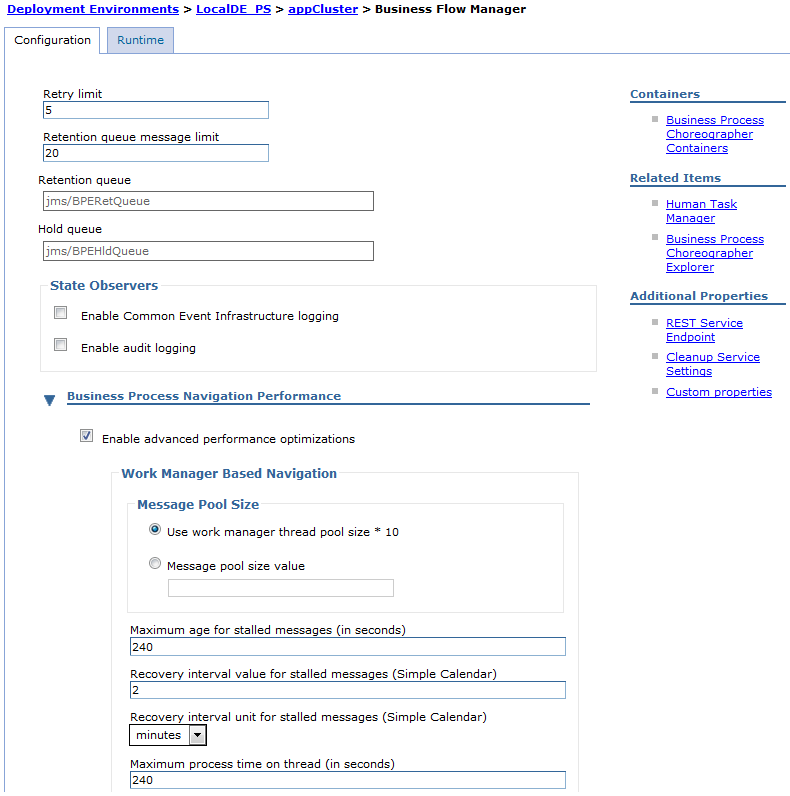

- Click New to add a new custom property.
- Enter ProcessAdministration as the name and the value for the process administration mode.
Delete this custom property will return process administration to instance-based authorization, but only for new process instances, activities, and scopes.
Save the changes.
- Activate the changes by restarting the cluster where Business Process Choreographer is configured.
The new process administration behavior applies to all new process instances. The behavior of existing instances depends on the position of the process navigation when the administration settings were changed. Activities before the current navigation position continue to be subject to the administration mode that was active when they were started. For all other activities, the new administration mode applies.
Alternative administration modes for BPEL processes
The alternative administration modes can help you to reduce response times for queries on tasks and processes by reducing the number of objects that are created in the Business Process Choreographer database to administer processes and activities.
You can set the administration mode in the administrative console by assigning one of the following values to the Business Flow Manager ProcessAdministration custom property.
- optimize
- Optimize process administration. In this mode, no default administration tasks are created at run time if a process template does not have any administration tasks defined. This mode reduces only the number of objects that are created; the set of users that can administer or monitor process, activity, and scope instances is not changed.
- useProcessAdminAuthorizationOnly
- Restrict process administration to authorization. If a process template was modeled to include administration tasks, this administration mode deactivates them and all actions related to them, such as escalations
associated with the administration task.
The set of users that can administer or monitor process, activity, and scope instances is not changed by this administration mode. However, if the process or any of its activities have replacement variables that reference the modeled administration task, the people query for the task cannot be resolved, and the default people assignments apply.
- useSystemAdminAuthorizationOnly
- Restrict process administration to system administrators. If your process template was modeled to include administration tasks, this administration mode deactivates them and all actions related to them, such as escalations and monitoring. In addition, instance-based authorization is disabled thus restricting process administration and monitoring to users who are system administrators and system monitors.
If you do not specify an administration mode, instance-based authorization applies to actions on processes, activities, and scopes. In addition, administration tasks are created as defined in the process template. If the process template does not have any administration tasks, a default administration task is created at run time when a process instance is started.
If you change the administration mode, the new mode applies to all new process instances. For existing instances, the administration mode used depends on the position of the process navigation when the administration mode was changed. Activities before the current position are subject to the administration mode that applied when the instances were created. For all other activities, the new administration mode applies. Take care to avoid any disruption to people or automated processes that perform administrative actions using user IDs not in the appropriate role.
Additional information on restricting process administration to system administrators
This process administration mode is the most restrictive. A different set of rules applies to what happens when a new process instance is started and which user IDs are allowed to view, monitor, or perform administrative actions on process instance, scope instances, and activity instances.
This administration mode might not be suitable for your needs if any of the following conditions apply to your system:
- Your BPEL process relies on actions that are associated with modeled administration tasks, for example, escalations.
- If adding the users that need to perform the modeled administration tasks to the BPESystemAdministrator role, grants these users more rights than they need.
When process administration is restricted to system administrators, the following rules apply to administering and monitoring process instances, scope instances, and activity instances.
- Process instances
- When a new process instance is started, whether by a user or another component, no administration task instance is created for the process instance. The only work item created for the process instance is the process starter work item.
- Administration
- Only users in the BPESystemAdministrator role can perform administration actions on the process instance. For example, terminating or restarting a failed process instance, or updating the contents of a global or local variable.
- View and monitoring
- Only users in either the BPESystemAdministrator role or BPESystemMonitor role can view or monitor the process instance or parts of it. For example, viewing the progress of a process instance in the Business Process Choreographer Explorer, or using Business Flow Manager APIs to read the contents of variables that belong to a process instance.
- Scope instances
- When a scope that has an associated administration task is activated, no administration task instance is created and no work item is created.
- Administration
- Only users in the BPESystemAdministrator role can perform administration actions on the scope instance. For example, jumping from one activity in the scope to another activity, or performing a skip, force-retry, or force-complete on an activity inside the scope.
- View and monitoring
- Only users in either the BPESystemAdministrator role or BPESystemMonitor role can view or monitor the scope instance or parts of it.
- Activity instances
- When an activity instance needs an administrative action performed on it, for example, because it stops due to a failure in its implementation, no administration task or work items are created.
- Administration
- Only users in the BPESystemAdministrator role can perform administration actions on the activity instance. For example, performing a force-complete, force-navigate, or force-retry on an activity instance that stopped.
- View and monitoring
- Only users in either the BPESystemAdministrator role or BPESystemMonitor role can view or monitor the activity instance or parts of it. For example, reading the contents of variables that belong to an activity instance.
Listing information about process and task templates
Use the listTemplates.py administrative script to list instance and version information about deployed BPEL process and task templates. This script provides an overview of which versions of a template are deployed with which applications. The information can help you identify whether an old version of an application can be undeployed. An application cannot be undeployed if there are any instances of any BPEL process templates or human task templates belonging to the application, regardless of the state of the instance.
The following conditions must be met:
- If the user ID does not have operator authority, include the wsadmin -user and -password options to specify a user ID that has operator authority.
- If you are not working with the default profile, use the wsadmin -profileName profile option to specify the profile.
- Change to the Business Process Choreographer subdirectory where the administrative script is located.
 Enter the following command:
- cd install_root/ProcessChoreographer/admin

 Enter the following command:
- cd install_root/ProcessChoreographer/admin
 Enter the following command:
- cd install_root\ProcessChoreographer\admin
- Run the script to display the information.
- Enter the following command:
install_root/bin/wsadmin.sh -f listTemplates.py -cluster clusterName [-templateName templateName] [-applicationName applicationName] (-all | -active | -stopped | -invalid | -superseded) [-countInstances] [-groupBy (application | template)] -
Enter the following command:
install_root/bin/wsadmin.sh -f listTemplates.py -cluster clusterName [-templateName templateName] [-applicationName applicationName] (-all | -active | -stopped | -invalid | -superseded) [-countInstances] [-groupBy (application | template)] -
Enter the following command:
install_root\bin\wsadmin -f listTemplates.py
     -cluster clusterName      [-templateName templateName]
     [-applicationName applicationName]
     (-all | -active | -stopped | -invalid | -superseded)
     [-countInstances]
     [-groupBy (application | template)]
Where:
- -cluster clusterName
- The name of the cluster where Business Process Choreographer is configured. In a multicluster setup, you must specify the application cluster because that is where Business Process Choreographer is configured.
- -templateName templateName
- Optionally restricts the list to a particular temple.
- -applicationName applicationName
- Optionally restricts the reported information to the specified application. The default is to report information about all applications on the cluster.
- -all | -active | -stopped | -invalid | -superseded
- You can specify one of these options to restrict the list to a subset of the instances.
- -all
- Lists all valid templates. That is, templates that belong to a deployed application. This behavior is the default.
- -active
- This option lists only valid templates that are in the state active.
- -stopped
- This option lists only valid templates that are in the state stopped.
- -invalid
- This option lists only templates that are in the Business Process Choreographer database, but do not belong to any deployed application.
This is the only option that displays invalid templates.
If you use this option, the script requires access to the Business Process Choreographer database, so you run the script in connected mode and at least one cluster member must be running.
- -superseded
- This option lists only templates for which a newer version is available in the runtime system, regardless of their state.
- -countInstances
- Optionally provides a count of how many instances of each template are in the system.
If you use this option, the script requires access to the Business Process Choreographer database, so you run the script in connected mode, and at least one cluster member must be running.
- -groupBy (application|template)
- Optionally groups the information by application or by template.
For example, to list information about all versions of the application myApp deployed on the cluster myCluster, including how many instances there are of each template version:
Enter the following command:
- wsadmin.sh -f listTemplates.py -cluster myCluster -application myApp -all -countInstances
Enter the following command:
- wsadmin.sh -f listTemplates.py -cluster myCluster -application myApp -all -countInstances
Enter the following command:
- wsadmin -f listTemplates.py -cluster myCluster -application myApp -all -countInstances
The script outputs the information in a table that has the following columns:
- Application name
- Version
- Template name
- Valid-from date
- Number of instances
-
- To identify application templates that could be removed, look for superseded versions that have zero instances. Then perform Browsing and administering modules to check whether any SCA modules depend on the services exported by the application. By removing applications that are no longer needed, you can speed up how fast your server starts.
- To uninstall a particular application template, but it still has running instances, consider performing any of the following.
- Allow more time for the running instances to reach an end state, then run the script again.
- Identify whether the running BPEL process instances can be migrated to a newer template instance.
- Investigate the reasons why particular instances have not reached an end state, and consider whether it is acceptable to force any of then into an end state.
You have the latest information about the applications.
Administer BPEL process and task templates
Use the administrative console or the administrative commands to administer BPEL process and task templates.
Process templates define BPEL processes and task templates define human tasks within an enterprise application. When an enterprise application that contains process or task templates is deployed and started, the templates are put into the started state. You can use the administrative console or the administrative commands to stop and start process and task templates. You can use Business Process Choreographer Explorer to view information about the started templates.
Stop and starting process templates using the administrative console
You can use the administrative console to start and stop BPEL process templates individually.
Before you begin this procedure, the following conditions must be met:
- If WebSphere administrative security is enabled, verify the user ID has operator authority.
- The application server, on which the process templates are to be stopped or started, must be running. That is, the -conntype none option of wsadmin cannot be used, because a server connection is required.
The following steps describe how to use the administrative console to stop and start process templates.
- Select the module to manage.
In the navigation pane of the administrative console, click Applications > SCA modules > module_name .
- In the Configuration page for the SCA module under Additional Properties, click Business processes, and then a process template.
- To stop the process template, click Stop.
Existing instances of the process templates continue to run until they end normally, but you cannot create new instances from the stopped template. If the process is a subprocess, the creation of new instances depends on whether the subprocess is a peer or a child of the calling process. If the process template is part of a process application, the business BPD cannot start new instances of the BPEL process, and therefore it cannot run to completion.
- To start the process template, click Start.
- To stop the process template, click Stop.
Stop and starting task templates using the administrative console
Use the administrative console to start and stop task templates individually.
If WebSphere administrative security is enabled, verify the user ID has operator authorization.
Task templates define Service Component Architecture (SCA) services that are represented as stand-alone tasks within an enterprise application. When an enterprise application that contains task templates is deployed and started, the task templates are put into the start state.
- Select the module to manage.
In the navigation pane of the administrative console, click Applications > SCA modules > module_name .
- In the Configuration page for the SCA module under Additional Properties, click Human tasks, and then select the task templates.
- To stop the task templates, click Stop. You cannot create new instances from the stopped template. In addition, if the template is part of a process application, the business BPD cannot start new instances of the task, and therefore it cannot run to completion.
- To start the task templates, click Start.
Stop and starting process and task templates using administrative scripts
Use an administrative script to stop and start all templates that belong to an application, as an alternative to the administrative console for stopping and starting process and task templates individually.
The following conditions must be met:
- If the user ID does not have operator or administrator authority, include the wsadmin -user and -password options to specify a user ID that has operator or administrator authority.
- Run the script in connected mode, that is, do not use the wsadmin -conntype none option.
- If you are not working with the default profile, use the wsadmin -profileName profile option to specify the profile.
The following steps describe how to use an administrative script to stop and start the process and task templates that belong to an application.
- Change to the Business Process Choreographer subdirectory where the administrative script is located.
Enter the following command:
- cd install_root/ProcessChoreographer/admin
Enter the following command:
- cd install_root/ProcessChoreographer/admin
Enter the following command:
- cd install_root\ProcessChoreographer\admin
- To stop the process and task templates: Enter the following command:
install_root/bin/wsadmin.sh -f bpcTemplates.jacl
                            -stop application_name
Enter the following command:
install_root\bin\wsadmin -f bpcTemplates.jacl
                         -stop application_name
Enter the following command:
install_root/bin/wsadmin.sh -f bpcTemplates.jacl
                            -stop application_name
Where:
- -stop application_name
- Stops all templates that belong to the named application.
Existing instances of the process templates continue to run until they end normally, but you cannot create new instances from the stopped template. If the process is a subprocess, the creation of new instances depends on whether the subprocess is a peer or a child of the calling process. If the process template is part of a process application, the business BPD cannot start new instances of the BPEL process, and therefore it cannot run to completion.
- To start the process and task templates: Enter the following command:
install_root/bin/wsadmin.sh -f bpcTemplates.jacl
                            -start application_name
Enter the following command:
install_root\bin\wsadmin -f bpcTemplates.jacl
                         -start application_name
Enter the following command:
install_root/bin/wsadmin.sh -f bpcTemplates.jacl
                            -start application_name
The templates belonging to the application start. You can use Business Process Choreographer Explorer to start process instances from the process templates, and work with task instances associated with the task template.
Manage the lifecycle of BPEL processes using Business Process Choreographer Explorer
After a BPEL process starts, it goes through various states until it ends. As a process administrator, you can take various actions on a process throughout its lifecycle.
Start a new process instance
You can start a new BPEL process instance from any of the BPEL process templates that you are authorized to use. All of the installed and started process templates are shown in the list of process templates in Business Process Choreographer Explorer. To start a new process instance.
- Display the process templates that you are authorized to use.
Click All Versions under Process Templates in the Views tab navigation pane.
- Select the check box next to the process template and click Start Instance.
This action displays the Process Input Message page.
If the process has more than one operation, this action displays a page that contains all of the available operations. Select the operation that is to start the process instance.
- Provide the input data to start the process instance.
If the process is a long-running process, you can type in a process instance name. If you do not specify a name, a system-generated name is assigned to the new process instance.
Complete the input for the process input message.
- To start the process, click Submit.
The process instance is started. If the process contains an activity that requires human interaction, a task is generated that can be claimed by any of the potential owners. If you are one of these potential owners, this task appears in the list on the My To-dos page.
If the process instance is a microflow, a process output message is displayed automatically in the web browser. For long-running processes that are not automatically deleted after the process completes, a process output message is available in the process instance view. To see the output message, select the instance in a process list in Business Process Choreographer Explorer, and open the process instance view. Not all processes have output messages, for example, if the process implements a one-way operation, an output message is not available.
Monitor the progress of a BPEL process instance
You can monitor the progress of a process instance to determine whether you need to take action so the process can run to completion.
In Business Process Choreographer Explorer to monitor the progress of a process instance.
- Display a list of process instances.
For example, click Administered By Me under Process Instances in the Views tab navigation pane.
- Select the check box next to the process instance and click View Process State.
The Process State page is displayed. This page shows the activities, the links including the transition and join conditions for the links, the fault handlers, the compensation handlers, and the event handlers that are defined for the process. Activities are color coded in the diagram, depending on their state. All states have an associated icon. For example, completed activities are indicated by a check mark. See the online help for the page.
- To act on an activity, click the activity, and select Show Activity Details.
Click an activity in the process state view. Use the choices in the pop-up menu, to display the activity details, skip the activity (mark an activity for skipping), or select it as the source for a jump to a different activity in the process. You can also repair switch activities that failed due to a problem with the evaluation of a case condition.
The available actions are displayed. Select the action of your choice.
View and modifying the variables of an activity
View and modify the activity variables of a process instance using Business Process Choreographer Explorer.
To see all of the variables of an activity, you need at least scope reader or process reader authority. To modify a variable you need scope administrator or process administrator authority. You can view all the exposed variables of an activity. If the variable can be changed and you have the correct authorization, you can modify the value of the variable.
Complete the following steps in Business Process Choreographer Explorer.
- In the Views tab, navigate to the Process Instance page. Complete one of the following actions:
- Click View Process State. Then click the relevant activity in the process state diagram, and click Show Activity Variables. You see the variables visible for the selected activity. Use the list to select a different activity in this process instance and display the visible variables.
- Click Activity Variables. Use the list to select an activity in this process instance and to display the visible variables.
- Click Skip Activities. Select an activity, and then click Set Variables. You see the variables visible for the selected activity. Use the list to select a different activity in this process instance and to display the visible variables.
- Select a variable name to see the current value.
- Click Edit to modify the value, and click Save to update the value settings of the variable.
The Edit action is available only if the variable settings can be modified.
Suspending and resuming BPEL process instances
You can suspend a long-running, top-level process instance. You might want to do this, for example, so that you can configure access to a back-end system used later in the process, or to fix a problem that is causing the process instance to fail. When the prerequisites for the process are met, you can resume the process instance.
To suspend and resume process instances, you must be a process administrator or system administrator. However, if Business Flow Manager is using the alternative process administration mode that restricts process administration to system administrators, then only users in the BPESystemAdministrator role can perform this action.
To suspend a process instance, the process instance must be in either the running or failing state. To resume a process, the process instance must be in the suspended state. To suspend or resume a process instance in Business Process Choreographer Explorer.
- Display a list of process instances.
For example, click Administered By Me under Process Instances in the Views tab navigation pane.
- Suspend the process.
Select the check box next to the process instance and click Suspend.
- Choose one of the options to suspend the process instance.
- To suspend the process until it is manually resumed, select Suspend.
- To suspend the process until a certain time, select Suspend process until, and specify the date and time.
- To suspend the process for a period of time, select Suspend process for, and specify the duration.
- To confirm your selection, click Submit.
This action suspends the specified top-level process instance. The process instance is put into the suspended state. Subprocesses with the autonomy attribute set to child are also suspended if they are in the running, failing, terminating, or compensating state. However, you can still complete any active activities and tasks that belong to the process instance.
To resume a process instance that is in the suspended state, select the process instance and click Resume.
The process instance and its subprocess are put into the states they had before they were suspended, for example, running. The process instance and its subprocesses resume.
Terminating BPEL process instances
You might want to terminate a process instance, for example, if the work or documents it represents are no longer needed, if no one is available to complete the process instance, if you have encountered problems with the process template and it needs to be redesigned, and so on.
To terminate a process instance, you must be a process administrator or system administrator. However, if Business Flow Manager is using the alternative process administration mode that restricts process administration to system administrators, then only users in the BPESystemAdministrator role can perform this action. In Business Process Choreographer Explorer to terminate a process instance. If compensation is defined for the process model, you can choose to terminate the process instance with compensation.
- Display the process instances that you can administer.
Click Administered By Me under Process Instances in the Views tab navigation pane.
- Select the check box next to the process instance to stop.
- To terminate the process instance with compensation, click Compensate.
This action terminates the process instance and starts compensation processing.
- To terminate the process instance without compensation, click Terminate.
This action stops the process instance immediately without waiting for any outstanding activities or tasks.
- To terminate the process instance with compensation, click Compensate.
Delete BPEL process instances using Business Process Choreographer Explorer
Process templates can be modeled so that process instances are not automatically deleted when they complete. You can explicitly delete these process instances after they complete.
To delete a process instance, you must be a process administrator or system administrator. However, if Business Flow Manager is using the alternative process administration mode that restricts process administration to system administrators, then only users in the BPESystemAdministrator role can perform this action.
The process instance must be in the finished, failed, terminated, or compensated state.
Completed processes instances are automatically deleted from the Business Process Choreographer database if the corresponding property is set for the process template in the process model.
You might want to keep process instances in the database, for example, to query data from process instances that are not written to the audit log, or to defer the deletion of processes to off-peak times. However, old process instance data that is no longer needed can impact disk space and performance. Therefore, you should regularly delete or archive process instance data that you no longer need or want to maintain. Make sure that you run this maintenance task at off-peak times.
You can delete completed process instances using either Business Process Choreographer Explorer, for example, to delete individual process instances, or the deleteCompletedProcessInstances administrative script to delete several process instances at once. Alternatively, you can archive completed process instances in the Business Process Archive database.
In Business Process Choreographer Explorer to delete a process instance.
- Display the process instances that you administer.
Click Administered By Me under Process Instances in the Views tab navigation pane.
- Select the process instance to delete and click Delete.
This action deletes the selected process instance from the database.
Repairing BPEL processes and activities using Business Process Choreographer Explorer
If a BPEL process runs into problems, you can analyze the process and then repair the activities. Business Process Choreographer Explorer provides various views for the process administrator to monitor the processes that are currently running.
The failure behavior of your process is controlled by the Continue On Error setting of the process template. If Continue On Error is set to no, any unexpected failure causes the affected activity to go to the stopped state.
If Continue On Error is set to yes (or if it is not set because your process was created with a WebSphere Integration Developer version earlier than 6.1.2) and an unexpected failure occurs, the default fault handler is invoked and ultimately causes the process to end in a failed state. The latter happens because with an unexpected failure there is no appropriate fault handler in the directly surrounding scope. When there is no explicit fault handler defined for the current fault and the default fault handler is invoked, it terminates the current scope and propagates the fault to the surrounding scope. Ultimately, this will cause the process to end in the failed state.
For invoke, Java snippet, human task, and custom activities you can model a dedicated Continue On Error setting and override the process setting. However, if you leave the default value the same as for the process, you can repair failure situations for these activity types. The setting at the activity level controls only the behavior of faults that are generated by the implementation of the activity. Faults that occur during the evaluation of the join condition, or during the evaluation of the transition condition of outgoing links are still controlled by the setting at the process level. Therefore, for example, an invoke activity can go to the stopped state (if, for example, the evaluation of its join condition failed) even if the Continue On Error setting at the activity level is set to yes.
If your activity stops, the process remains in the running state. You then have several options in Business Process Choreographer Explorer to repair the process and continue navigation.
- To view process instances with activities in the stopped state, define your own process instance search. Or, click Stopped Activities under Activity Instances in the navigation pane, and then click the relevant process instance of the failed activity.
- To view process instances with activities in the stopped state, click Critical Processes under Process Instances in the navigation pane.
- To monitor the progress of a specific process instance, click View Process State in any view that displays a list of process instances.
You can now take action to repair the pending activities.
Analyzing the cause of a failed BPEL process
Check information about an exception which caused a BPEL process to fail. If the process is in the failed state, you cannot repair the instance itself but you might be able to fix the cause of the problem to prevent the failure of future instances.
The process must be in the failed state. Any exception that occurs during process navigation which is not one of the faults defined for the process can lead to a failed process.
Complete the following steps in Business Process Choreographer Explorer.
- In the Views tab, navigate to the Process Instance page of the process.
For example, define a new process instance search to look for processes in the failed state, and click the failed process to see the process instance details.
- Select the Error Details tab to see more information about the failure of your process.
- Repair the cause of the failure to avoid further failures of instances of this process template.
Modify the variables of a stopped activity
Check the variables of an activity, and repair the process variables if they caused the activity to stop.
The process must be in the running state. To see the exposed variables of an activity, you need at least scope reader or process reader authority. If the value of the variable can be modified, you must be a scope administrator or system administrator to modify it. However, if Business Flow Manager is using the alternative process administration mode that restricts process administration to system administrators, then only users in the BPESystemAdministrator role can perform this action. During the lifetime of a process, problems can occur due to incorrect or missing values in the variables that control the BPEL process behavior. You can access all the exposed variables of an activity and repair the process by modifying the variable values. After you make the changes, you can continue process navigation.
Complete the following steps in Business Process Choreographer Explorer.
- In the Views tab, navigate to the Process Instance page.
For example, on the Critical Processes page, click the name of a process instance. On the Process Instance page, click the Activities tab, and click the name of the stopped activity.
Alternatively, to view stopped activities, click Stopped Activities under Activity Instances in the navigation pane. Then click the relevant activity.
- Click Variables to get a list of all of the variables visible to the activity.
- Select a variable name to see the value.
- Click Edit to modify the value, and click Save to update the value settings of the variable.
Although the Save action is always available, you might get an error message if the variable cannot be modified.
Restarting activities
You can restart an activity using new input data, for example, if you repaired the variables of an activity.
Generally, you can restart an activity if it is in the stopped state and the stopReason is Implementation failed or Follow-on navigation failed. Depending on the type of activity, you can restart the activity if it is in a state other than the stopped state. For more information on restarting activities in other states, see the related information on state transition diagrams for activities. To restart an activity in Business Process Choreographer Explorer.
- In the Views tab, navigate to the Activity page for the activity and click Restart.
For example, on the Process Instances Administered By Me page, click the name of a process instance. On the Process Instance page, click the Activities tab, and click the name of the activity you want to restart.
- Depending on the Stop Reason and the activity kind, you can specify the input data that is needed to start the activity again.
You can, optionally, specify the process Continue on Error setting is overridden for this activity. Clear the Continue on Error setting if you want the activity to stop again if an error occurs when the activity restarts.
- If an expiration time is set for the activity, specify the expiration behavior for the restarted activity.
- Click Restart.
Forcing the completion of activities
If you are aware that an activity is not going to complete in a timely manner, for example, because the invoked service is no longer available, you can force the completion of the activity so the process flow can continue. You might also want to force the completion of an activity if you cannot repair the cause of the failure. For example, if the evaluation of a wait expression in a wait activity repeatedly causes the activity to stop, you might want to force the activity to complete.
Generally, you can force an activity to complete if it is in the stopped state and the stopReason is Implementation failed, Follow-on navigation failed, or Exit condition is false. Depending on the activity kind, you can also force the completion of the activity in states other than the stopped state. For more information on forcing the completion of activities in other states, see the related information on state transitions diagrams for activities. To force the completion of an activity in Business Process Choreographer Explorer.
- In the Views tab, navigate to the Activity page for the activity, and click Force Complete.
- Set the data that is needed to complete the activity.
You can only provide data for activities that have output variables, that is, invoke, human task, pick, and receive activities.
- Click Force Complete again.
Rescheduling activities
You can reschedule activities using new date and time data in Business Process Choreographer Explorer.
Generally, you can reschedule pick, invoke, and staff activities if they are in the running, waiting, ready, or claimed state. Also, you can repair an activity that stopped because the timeout expression cannot be evaluated.
To reschedule an activity, you must be a system administrator or an administrator of the activity, an enclosing scope, or the process. However, if Business Flow Manager is using the alternative process administration mode that restricts process administration to system administrators, then only users in the BPESystemAdministrator role can perform this action. To reschedule an activity in Business Process Choreographer Explorer.
- In the Views tab, navigate to the Activity Instance List page. Select the activity you want to reschedule, and click Reschedule. Alternatively, click the name of the activity you want to reschedule and, on the Activity page, click Reschedule.
- On the Reschedule Activity page, specify a date and time to reschedule the activity. Alternatively, you can specify the activity is never rescheduled or that it is immediately rescheduled.
- Then click OK.
Repairing stopped activities
You can use Business Process Choreographer Explorer to manually intervene in the navigation of a BPEL process. You can repair activities that stopped because problems occurred, for example, during an expression evaluation.
Use this procedure for any of the following situations:
- An activity stopped because the evaluation of a join condition failed. The stopReason is Activation failed.
- A switch activity stopped because the evaluation of a case condition failed. The stopReason is Implementation failed.
- A while or repeatUntil activity stopped because the evaluation of a loop condition failed. The stopReason is Implementation failed.
- A forEach activity stopped because the evaluation of a loop condition failed. The stopReason is Implementation failed.
- An activity stopped because the evaluation of a transition condition failed. The stopReason is Follow-on navigation failed.
- An activity stopped because the exit condition evaluated to false when evaluated on the completion of the activity. The stopReason is Exit condition is false.
Usually the administrator tries to force a retry of the activity or to force the completion of the activity. For activity failures that cannot be repaired with these actions, you can override the navigation of the activity using Business Process Choreographer Explorer.
For details about the problem, click Error Details on the Activity page. You might need to modify variable values before you continue with the repair action. Furthermore, you can jump from one activity of a process instance to another activity, which is described in the topic on jumping activities. You might want to use a skip activity option to mark a failing activity to be skipped in subsequent process instances. Also, you might want to skip the processing of a stopped activity or mark it to be skipped when it gets processed again.
To repair a stopped activity, complete the relevant step in Business Process Choreographer Explorer.
- To view stopped activities, click Stopped Activities under Activity Instances in the navigation pane, and then click the relevant activity.
- You can now take the relevant action to repair the pending activity.
- An activity stopped because the evaluation of a join condition failed. The stopReason is Activation failed.
Complete the following steps:
- In the Views tab, navigate to the Activity page for the activity, and click Repair Join.
- Select the relevant option to continue processing. You can specify the join condition is reevaluated, and the navigation of the process instance continues. Alternatively, you can specify the value of the join condition for the activity is set to true or false to determine if the navigation of the current branch continues.
If a value of True is specified, the activity is started. If a value of False is specified, the behavior depends on the suppressJoinFailure process attribute. If this attribute is set to yes, the activity is skipped and the status of all outgoing links of this activity is set to false. Otherwise, the joinFailure standard fault of Business Process Execution Language is given.
- Click Continue to force the activity navigation.
- A switch activity stopped because the evaluation of a case condition failed. The stopReason is Implementation failed.
Complete the following steps:
- In the Views tab, navigate to the Activity page for the activity, and click Force Case Navigation.
- Select the branch that is to be followed during the navigation. The branches are enumerated according to their position in the model. You can only select one branch.
- Click Submit to force the case navigation.
- A while or repeatUntil activity stopped because the evaluation
of a loop condition failed. The stopReason is Implementation
failed. Complete the following steps:
- In the Views tab, navigate to the Activity page for the activity, and click Next Iteration or End Loop to force the navigation of the activity.
- A forEach activity stopped because the evaluation of a loop condition failed. The stopReason is Implementation failed.
Complete the following steps:
- In the Views tab, navigate to the Activity page for the activity, and click Repair For Each.
- Set the relevant values to continue processing. Specify a value for the start counter and the final counter. If the forEach activity has an early exit condition, also specify a value for the number of iterations to be completed.
- Click Continue to force the activity navigation.
- An activity stopped because the evaluation of a transition condition failed. The stopReason is Follow-on navigation failed. Complete the following steps:
- In the Views tab, navigate to the Activity page for the activity, and click Force Navigation.
- Select the names of the links that are to be followed during navigation. The displayed names of the links are the names that are determined in IBM Integration Designer during the modeling of the process. You can select an arbitrary number of links.
- Click Submit to force the activity navigation.
- An activity stopped because the exit condition evaluated to false when evaluated on the completion of the activity. The stopReason is Exit condition is false. Complete the following steps:
- In the Views tab, navigate to the Activity page for the activity, and click Restart or Force Complete.
- Set the data that is needed to restart or complete the activity.
- Click Restart or Force Complete to force the activity navigation.
- An activity stopped because the evaluation of a join condition failed. The stopReason is Activation failed.
Complete the following steps:
Repairing stopped activities using the process state view
Use the process state view in Business Process Choreographer Explorer, you can manually repair activities that stopped.
You can use this procedure if the evaluation of a join condition, loop condition, case condition, transition condition, or a forEach counter value failed and the corresponding activity is stopped.
To perform this task, you must be a process administrator or system administrator. However, if Business Flow Manager is using the alternative process administration mode that restricts process administration to system administrators, then only users in the BPESystemAdministrator role can perform this action. To repair a stopped activity using the process state view, complete the relevant step in Business Process Choreographer Explorer.
- To view the stopped activities of a process instance, click Process Instances > Critical Processes in the navigation pane. Then select the check box next to the relevant process instance, and click View Process State. One or more stopped activities or activity gateways might be listed. Alternatively, select Activity Instances > Stopped Activities.
- Depending on the problem that occurred, you can now use repair actions to repair the activity.
- An activity stopped because the evaluation of a join condition failed. The stopReason is Activation failed.
Complete the following steps:
- Click the activity gateway or, for a single incoming link, click the activity.
- Click Repair Join and choose to either reevaluate the condition or to force the result of the evaluation to true or false.
- The evaluation of the loop condition failed for a While or Repeat
Until activity. The stopReason is Implementation
failed. Complete the following step:
- Click the activity, and select either Next Iteration to continue the loop or End Loop and to end the loop.
- The evaluation of a case condition failed for a switch activity.
The stopReason is Implementation failed.
Complete the following steps::
- Click the activity, and click Force Case Execution. Select the case to be executed.
- An activity stopped because the evaluation of a transition condition failed. The stopReason is Follow-on navigation failed. Complete the following steps::
- Click the activity gateway or, for a single outgoing link, click the link.
- Click Repair Follow-on Navigation . The target nodes and links of the available branches are highlighted.
- To select one or more branches, click the target nodes or links, and select Select this Branch.
- Then click a target node, link, or the source node, and click Force Navigation to force the navigation of the selected branches.
- The evaluation of counter values failed for a forEach activity.
The stopReason is Implementation failed.
Complete the following steps::
- Click the activity, and click Repair For Each.
- Enter start and final counter values and, optionally, the number of iterations to run to either continue or end the loop.
- Click the activity, and click Repair For Each.
- An activity stopped because the evaluation of a join condition failed. The stopReason is Activation failed.
Complete the following steps:
Repairing correlation sets
You can view and modify the correlation sets for an activity using Business Process Choreographer Explorer. Additionally, you can repair activity correlation sets that are incorrect due to runtime faults or repair actions, or due to jump operations in the BPEL process.
To repair the correlation sets that are associated with an activity, you must be a process administrator or system administrator. However, if Business Flow Manager is using the alternative process administration mode that restricts process administration to system administrators, then only users in the BPESystemAdministrator role can perform this action. You might want to repair an activity correlation set if, for example, the activity is in the stopped state because the correlation set values do not match the expected values.
In Business Process Choreographer Explorer.
- In the Views tab, navigate to the Activity page for the activity, and select the Correlation tab to see the correlation sets that are associated with the activity.
- Click Repair Correlation Sets to modify the correlation sets.
- If there is more than one correlation set defined, use the drop-down list to select the correlation set to modify.
- If the correlation set is uninitialized, you can specify the values for the correlation set, and click Initialize to save the values.
- If the correlation set is already initialized and you want to change the values, first click Uninitialize to remove the existing values. Then you can specify the new values for the correlation set, and click Initialize to save these values.
All correlation sets contain the correct property values.
If the activity is stopped, you can continue to repair the process by restarting the activity.
Jumping activities
You can jump from one activity to another activity in the BPEL process instance. You can select to complete the source activity before you jump to a target activity.
To perform this action, either be a system administrator or be a process or scope administrator of the scope or a parent scope to which the source and target activities belong. However, if Business Flow Manager is using the alternative process administration mode that restricts process administration to system administrators, then only users in the BPESystemAdministrator role can perform this action.
To jump from one activity to another in Business Process Choreographer Explorer.
- In the Views tab, navigate to the Process State page of the process instance.
- Click the relevant activity in the process state diagram.
Note that jump actions are only available if the Detail level slider of the process state diagram is at the most detailed level.
- To go to another activity, click Jump to Another
Activity.
This option only available for activities in the running state ( ready, claimed, running, stopped, or waiting).
The process state diagram is displayed again, and only activities that qualify as target activities are selectable. For information on target activities, refer to the related information on activity jump targets.
- Select a target activity to choose an action to perform.
The actions that are available depend on the source activity.
- Choose an action to perform.
- To complete the source activity before you jump to the target activity, click Complete Source Activity and Jump.
The Complete Source Activity and Jump option is only available for target activities if the source activity is a human task activity in the claimed state. This option completes the source activity before you jump to a target activity.
- To force the completion of the source activity before you jump to the target activity, click Force Complete Source Activity and Jump. Then click Force Complete and Jump to complete the activity with the data that you provide.
The Force Complete Source Activity and Jump option is available for target activities if the source activity is a human task activity in the ready, claimed, or stopped state. It is also available for an invoke activity in the running or the stopped state, a receive or a wait activity in the waiting or the stopped state, and all other basic activities in the stopped state. This option forces the completion of the source activity before you jump to a target activity.
- To skip the activity and jump to another activity, click Skip Source Activity and Jump.
- Click Cancel Jump to cancel the jump action.
- To complete the source activity before you jump to the target activity, click Complete Source Activity and Jump.
Activity jump targets
When you jump from one activity to another activity in the BPEL process instance using Business Process Choreographer Explorer, you can select the target activity from a list of possible target activities. Certain restrictions apply when you select an activity that serves as a target activity for a jump action.
During the navigation of a process instance, you can only jump from an activity to activities that are directly nested either in the same sequence or cyclic flow. Additionally, you can jump within a flow if the source and target activity are connected by a series of flow links and there are no other links connected to any of the activities in between.
- You can perform activity jumps within sequence activities. This means the source activity and target activity of the jump must be in the same sequence and both are not nested in other structured activities.
- You can perform activity jumps within flow activities. In this case, the source activity and target activity of the jump can be directly nested in a flow activity and there must be only one path in the control flow from source to target.
- Additionally, you can jump outside of a scope if there is only one activity contained in the scope. For example, it is possible to jump from an invoke activity with an attached handler.
- You can also perform activity jumps within cyclic flows, whereby the source activity and target activity of the jump are also directly nested in the cyclic flow and are not nested in other structured activities.
Skipping activities in BPEL processes
You can skip an activity so that it is not included in the processing of the BPEL process instance.
To mark an activity to be skipped in Business Process Choreographer Explorer.
- In the Views tab, navigate to the Process State page of the process instance.
- Click the relevant activity in the process state diagram.
Note that skip and jump actions are only available if the Detail level slider of the process state diagram is at the most detailed level.
- Perform one of these skip actions.
- Click Skip Activity to mark this activity to be skipped. The activity is then indicated by the skip requested icon
 . Activities that are skipped are indicated by the skipped
icon
. Activities that are skipped are indicated by the skipped
icon  .
.
To perform this action, you must be a process administrator or a scope administrator of the scope or a parent scope to which the source and target activities belong.
The Skip Activity action is available for any activity state. An activity that is in an end state is marked to be skipped but the state of the activity remains unchanged until it is reached again by the navigation. Therefore, if an activity is already in an end state, the activity is skipped as soon as it is activated again.
- To unmark the activity to be skipped, click Cancel Skip. This cancels a previously selected skip activity request.
- Alternatively, to skip the activity and jump to another activity, click Jump to Another Activity.
The diagram is displayed again, and only activities that qualify as target activities are selectable. Note the options available depend on the source activity.
To skip the activity and jump to another activity, click Skip Source Activity and Jump.
- Click Skip Activity to mark this activity to be skipped. The activity is then indicated by the skip requested icon
Administer compensation for microflows using Business Process Choreographer Explorer
When a microflow runs, it can encounter problems. For these situations, compensation might have been defined for the BPEL process in the process model. Compensation allows you to undo previous completed steps, for example, to reset data and states so that you can recover from these problems. Undo actions are only necessary for activities that perform actions which do not participate in the transaction of the microflow.
For microflows to be compensated, the compensation service must be started in the administrative console. If a compensation action for a microflow fails, the process administrator must intervene to resolve the problem.
In Business Process Choreographer Explorer to administer failed compensation actions.
- Display a list of the compensation actions that failed.
Click Failed Compensations under Process Instances in the Views tab navigation pane.
The Failed Compensations page is displayed. This page contains information about why the named compensation action failed. This information can help you to decide what actions to take to correct the failed compensation.
- Select the check box next to the activity and then click one of the available actions.
The following administrative actions are available:
- Skip
- Skips the current compensating action and continues with compensating the microflow. This action might result in a non-compensated activity.
- Retry
- If you have taken action to correct the failed compensation action, click Retry to try the compensation action again.
- Stop
- Stops the compensation processing.
Create and starting a task instance
You can create and start a task instance from any of the task templates that you are authorized to use. All of the installed and started task templates with the newest valid from date are shown in the list of task templates in Business Process Choreographer Explorer. To create and start a task instance from a task template.
- Display the task templates that you are authorized to use.
Click My Task Templates under Task Templates in the Views tab navigation pane.
- Select the check box next to the task template and click Start Instance.
This action displays the Task Input Message page.
- Provide the input data to start the task instance.
- To start the task instance, click Submit.
The task instance is ready to be worked on.
Work on your tasks
To work on a task, you must claim the task, and then perform the actions needed to complete it. You can claim a task that is in the ready state if you are a potential owner or the administrator of that task. If you claim a task, you become the owner of that task, and are responsible for completing it.
Tasks for which you have the role of reader or editor also appear on your list of tasks.
To claim and complete a task with Business Process Choreographer Explorer.
- Display the tasks that have been assigned to you.
In the Views tab, click Task Instances > My To-dos.
This action displays the My To-dos page, which lists the tasks that have been assigned to you.
- Claim the task on which you want to work.
Select the check box next to the task, and click Work on.
This action displays the Task Message page.
- Provide the information to complete the task.
If you need to interrupt your work, for example, because you need more information from a co-worker to complete the task, click Save to save the changes you made.
- Click Complete to complete the task with the information that you provide.
The task that you completed is in the finished state. If you leave the task without completing it, the task remains in the claimed state.
Suspending and resuming task instances using Business Process Choreographer Explorer
You can suspend task instances using Business Process Choreographer Explorer. You might want to do this, for example, to fix a problem that is causing the task instance to fail. When the prerequisites for the task are met, you can resume running the task instance.
To suspend and resume a task instances, you must have task administrator authorization.
To suspend a task instance, the task instance must be in either the running or failing state. To resume a task, the task instance must be suspended.
Suspending tasks is only supported for human tasks that use the WebSphere Application Server simple calendar. To suspend a task instance in Business Process Choreographer Explorer.
- Display the task instances that you can administer.
Click Administered By Me under Task Instances in the Views tab navigation pane.
- On the Task Instance page, click Suspend.
- Choose one of the options to suspend the task instance.
- To suspend the task until it is manually resumed, select Suspend.
- To suspend the task until a certain time, select Suspend task until, and specify the date and time.
- To suspend the task for a period of time, select Suspend task for, and specify the duration.
- To confirm your selection, click Submit. The task instance is suspended.
To resume a task instance that is suspended, click Resume.
Restarting task instances using Business Process Choreographer Explorer
You can restart task instances using Business Process Choreographer Explorer. You might want to do this, for example, for a human task that is already running but not progressing as expected, or for a task that has reached an unexpected or undesired end state, such as failed or expired.
Additionally, you can change the input message values of tasks before you restart them. You can restart a task to reuse in order to initiate the same work again. This could be a human task that has finished, for example an invocation task or a collaboration task. Typically, you would restart this task with a changed input message.
The task instance can be a collaboration, invocation, or to-do task. The task instance can be in any state except inactive. Additionally:
- An invocation task cannot be in the running state.
- A to-do task cannot be in an end state, that is, it cannot be finished, failed, terminated, or expired. If the to-do task is forwarded, then the follow-on task cannot be in an end state.
- An inline to-do task cannot be in the ready state.
The task instance can be escalated, suspended, or waiting for subtasks. The caller must be the starter, originator, or an administrator of the task instance.
Restarting the task instance causes the people resolution to be newly performed and all timers to be reset. Any subtasks or follow-on tasks are deleted. Any escalations are canceled and reset into the inactive state. For invocation tasks, the logged-on user becomes the starter of the restarted task instance. To restart a task instance in Business Process Choreographer Explorer.
- In the Views tab, navigate to the Task page for the task, and click Restart.
- Click Restart to start the task again with the information you provide.
Rescheduling task instances
You can reschedule task instances using new date and time data in Business Process Choreographer Explorer.
You can update, reschedule, stop, and restart the expiration, deletion, and due times of a task. When a task is in the inactive state, after the task is created and before it is started, the task originator can update the reschedule time only to never reschedule or to immediately reschedule. This influences the scheduling of the time setting when the task is started. The task originator can modify the task duration after the task is created and before it is started.
When a task is in the ready, claimed, or running state, you can reschedule the due time and expiration time setting.
To change the due time setting of the task, you must be the owner, starter, originator, editor, or administrator of the task. To change the expiration time setting, you must be the originator or administrator of the task. To reschedule an task in Business Process Choreographer Explorer.
- In the Views tab, navigate to the Task instance page for the task, and click Reschedule.
For example, on the Process Instances Administered By Me page, click the name of a process instance. On the Process Instance page, click the Tasks tab, and click the name of the task you want to reschedule. On the Task instance page, click Reschedule.
- On the Reschedule Task page, select the time setting to modify, and specify a date and time for which to reschedule the task. Alternatively, you can specify the task is never rescheduled or that it is immediately rescheduled.
- Click OK to reschedule the task.
Manage priorities of human tasks in Business Process Choreographer Exploer
You can use the priorities of human tasks to filter for tasks, and to sort your list of tasks.
To change the priority of a task instance in Business Process Choreographer Explorer.
- Display a list of task instances.
For example, click My To-dos under Task Instances in the Views tab navigation pane.
- Select the check box next to the task instance, and click Change Priority.
- Enter a value, and click Submit.
The priority of the task instance is set to the new value.
To sort the list of tasks by priority, click the arrows in the table header.
View task escalations
An escalation notifies the escalation receiver that a user might have problems completing their assigned task on time.
When a task becomes overdue, it might result in an escalation. An escalation can result in the following actions:
- A new work item is created, for example, for a manager to take action to support the resolution of the problem.
- If you specified email settings when you configured the human task container, an email is sent to a designated person to inform them about the escalated task.
- An event notification handler is called.
Complete the following steps in Business Process Choreographer Explorer.
To view escalations, click My Escalations under Task Instances in the Views tab navigation pane.
- To view information about an escalation, click the escalation name.
- To view information about an escalated task, click the task name.
Sending emails for escalations
When a task becomes overdue, it might result in an escalation. You can set up your system to send emails to designated people to inform them about the escalation.
The following rules apply to escalation emails:
- Your people directory provider must support the specification of email addresses, such as LDAP or virtual member manager.
- The Everybody, Nobody, Group and Users by user ID people assignment criteria are not supported. For example, use User records by user ID instead.
- In Integration Designer, perform the following actions for the task in the Human Task editor.
- Under the task settings in the Details tab of the properties area, edit the value of the People
directory (JNDI name) field.
Set this field to one of the following values:
- bpe/staff/samplevmmconfiguration
- bpe/staff/samplevmmconfiguration
- The people directory configuration name (JNDI name) of your choice.
- Under the escalation settings in the Details tab of the properties area, set the value of the Notification type field to E-mail.
- Optional: Specify text for the body of the email that is sent for the escalation.
To insert a variable to include task specific information into the text, click Add Variable and select an appropriate variable from the list. In the editor, the variable will appear between "%" characters, but will be replaced when it is evaluated during execution in the runtime environment when the email is sent.
If you do not specify any text, the default message text is used.
- Under the task settings in the Details tab of the properties area, edit the value of the People
directory (JNDI name) field.
- In the administrative console for Process Server, perform the following actions.
- Ensure the simple mail transfer protocol (SMTP)
host is set. If authentication is enabled, set the User ID and password for the SMTP host.
In the administrative console, click Resources > Mail > Mail Sessions > HTMMailSession_nodeName_serverName to check this setting, or Resources > Mail > Mail Sessions > HTMMailSession_clusterName if Business Process Choreographer is configured on a cluster. The SMTP host is defined on the cell level.
- Ensure the sender email address (Sender
e-mail address) specified when you configure the human task manager is a valid email address.
In the administrative console, click Servers > Clusters > cluster_name. On the Configuration tab, in the Business Process Manager section, click Business Process Choreographer > Human Task Manager.
- Ensure the simple mail transfer protocol (SMTP)
host is set. If authentication is enabled, set the User ID and password for the SMTP host.
If a problem occurs with escalation emails, check the SystemOut.log file for error messages.
Manage work authorizations and assignments
After a task or BPEL process instance has started, you might need to manage work authorizations or assignments for the task or process, for example, to better distribute the work load over the members of a work group. A work item is the assignment of a business entity, such as a task or a process instance, to a person or a group of people for a particular reason. The assignment reason allows a person to play various roles in the business process scenario, for example, potential owner, editor, or administrator.
A task instance or a process instance can have several work items associated with it because different people can have different roles. For example, John, Sarah, and Mike are all potential owners of a task instance and Anne is the administrator; work items are generated for all four people. John, Sarah, and Mike see only their own work items as tasks on their list of tasks. Because Anne is the administrator, she gets her own work item for the task, and she can manage the work items generated for John, Sarah, and Mike.
Sometimes, you might need to change a task or process instance assignment after they are started, for example, to transfer a work item from the original owner to someone else. You might want to specify absence settings for the time you are away. You might also need to additional work items or delete work items that are not needed anymore.
Create work items for BPEL processes using Business Process Choreographer Explorer
Work items of a process instance are used to manage administrator or reader authorization for the process instance. You might want to process work items for new administrators, for example, when a user claims the ownership of a process instance because the user ID of the starter of the process instance will be deleted. You might also want to create work items if a user needs to see or modify variable values. This might happen, for example, in a long-running process if the organization has changed since the process started.
To create a work item for a process instance, you must be a process administrator or system administrator. However, if Business Flow Manager is using the alternative process administration mode that restricts process administration to system administrators, then only users in the BPESystemAdministrator role can perform this action. The process instance must be in the running, failing, or terminating execution state. Work items are automatically propagated to all enclosed activity instances. In Business Process Choreographer Explorer to create a work item.
- Display the process instances that you administer.
Click Administered By Me under Process Instances in the Views tab navigation pane.
- Select the check box next to one or more process instances for which you want to create a work item, and click Create Work Items. The Create Process Work Items page is displayed.
- Create the work items.
- In the New Owner field, enter the user ID for which the work item will be created.
- Select one or more roles from the Reason list.
The reason Administrator gives the user administrator authority for the process instance, while Reader gives reader authority.
- Click Create.
A work item is created for each role specified for the new work item owner.
Transferring BPEL process work items if you are the administrator of the process
You might need to change a work item assignment associated with a BPEL process. For example, you might want to transfer a process work item to another user because the ownership of the process instance needs to be claimed by another person. This might happen, for example, in a long-running process if the organization has changed since the process started.
The following conditions apply when you transfer a process work item:
- You must be a process administrator or system administrator. However, if Business Flow Manager is using the alternative process administration mode that restricts process administration to system administrators, then only users in the BPESystemAdministrator role can perform this action.
- The process instance must be in the running, failing, or terminating execution state.
- When work items with the assignment reasons administrator or reader are transferred, the transfer is automatically propagated to all enclosed activity instances.
In Business Process Choreographer Explorer to transfer a process work item.
- Display the process instances that you can administer.
Click Administered By Me under Process Instances in the Views tab navigation pane.
- Display the work items for a process instance.
In the Process Instances Administered By Me page, select the check box next to one or more process instances, and click Work Items.
- Transfer the work item.
- In the New Owner / Group Name field, enter either the user ID or the name of the group to which the work item will be transferred. Work items that are assigned to a user can only be transferred to another user, and work items that are assigned to a group can only be transferred to another group.
- Select one or more work items and click Transfer.
The transferred process work item with the new work item owner appears in the list of work items.
Claiming the ownership of BPEL process instances using Business Process Choreographer Explorer
You can transfer the ownership of a BPEL process instance by having a person with process administrator authorization take ownership of the process instance. You might want to do this, for example, in situations where the process starter is no longer with the company.
To transfer the ownership of a process instance, a process instance administrator or the system administrator for BPEL processes claims ownership of the process instance. The process instance for which process ownership is claimed can be in any state.
You need administrative rights to claim the ownership of a process instance. A system or process administrator can assign these rights by creating or transferring a process work item with the administrator reason. To claim the ownership of a process instance in Business Process Choreographer Explorer.
- Display a list of process instances.
For example, click Administered By Me under Process Instances in the Views tab navigation pane.
- Claim ownership of the process.
Select the check box next to the process instance or instances, and click Claim Ownership.
You are now the owner of the process instance, and the process starter. You also have process administrator rights for the process instance.
Delete work items for BPEL process using Business Process Choreographer Explorer
You might want to delete work items associated with a BPEL process, for example, if you created work items in error, or if they were generated for someone who no longer works for the company.
The following conditions apply when you delete a process work item:
- You must be a process administrator or system administrator. However, if Business Flow Manager is using the alternative process administration mode that restricts process administration to system administrators, then only users in the BPESystemAdministrator role can perform this action.
- The process instance must be in the running, failing, or terminating execution state.
- A work item with an assignment reason administrator can only be deleted when it is not the last work item with this assignment reason for the process instance.
- A work item for a specific user cannot be deleted when the work item is assigned to everybody.
- The deletion of a process reader or administrator work item is automatically propagated to all enclosed activities.
In Business Process Choreographer Explorer to delete a process work item.
- Display the process instances that you administer.
Click Administered By Me under Process Instances in the Views tab navigation pane.
- Display the work items for a process instance.
In the Process Instances Administered By Me page, select one or more process instances, and click Work Items.
- Delete the work items.
Select one or more work items and click Delete.
The process work items are deleted.
Transferring tasks that you own
If you are the owner of a task, you might need to transfer the task to another user, for example, if someone else needs to provide information to complete the task. In Business Process Choreographer Explorer to transfer a task that you own.
- Display the tasks that you own.
Click My To-dos in the Task Instances group of the Views tab navigation pane.
- Select the check box next to the task to transfer, and click Transfer.
- Transfer the task.
- In the New Owner / Group Name field, specify the user ID or the name of the group to which the work item will be transferred. You can transfer the task only to another potential owner of the task or the task administrator. Work items that are assigned to a user can only be transferred to another user, and work items that are assigned to a group can only be transferred to another group.
- Select one or more work items and click Transfer.
The transferred task appears on the list of tasks belonging to the new task owner.
Transferring task work items if you are the starter, originator, or administrator of the task
You might need to change a task work assignment after work begins on the task. For example, you might want to transfer a task work item to another user if the task owner is on vacation and the task must be completed before this person returns. The way in which you can transfer a work item depends on the role that you have, the state of the task, and the role the new owners or groups have.
To transfer a task work item you must have one of the following roles for the task, and the corresponding role for the work item as indicated in the Work item reason column. These roles and the task state determine who you can transfer the work items to.
| Your role | Work item reason | Task state | Work items can be transferred to the following user roles: |
|---|---|---|---|
| Owner | Owner | Claimed | Potential owner, administrator |
| Starter | Starter | Expired, terminated, finished, failed, or running | Potential starter, administrator |
| Originator | Originator | Any task state | Potential instance creator, administrator |
| Originator | Potential starter | Inactive | Any user role |
| Administrator | Starter | Expired, terminated, finished, failed, or running | Starter |
| Administrator | Potential starter | Inactive | Potential starter |
| Administrator | Reader or administrator | In any state except the inactive state | Reader, administrator |
| Administrator | Potential owner or editor | Ready, or claimed | Any user role |
In Business Process Choreographer Explorer to transfer a work item.
- Display the task instances that you can administer.
Click Administered By Me under Task Instances in the Views tab navigation pane.
- Display the work items for a task instance.
In the Task Instances Administered By Me page, select the check box next to one or more tasks, and click Work Items.
- Transfer the work item.
- In the New Owner / Group Name field, enter the user ID or the name of the group to which the work item will be transferred. Work items that are assigned to a user can only be transferred to another user, and work items that are assigned to a group can only be transferred to another group.
- Select one or more work items and click Transfer.
The transferred work item with the new work item owner appears in the list of work items.
Create task work items
You might want to create task work items for new potential owners, for example, when none of the current potential owners can accept any additional work. You might also want to create task work items if the query against the people directory does not return any potential owners. This might happen, for example, in a long-running process if the organization has changed since the process started.
To create a work item for a task instance, you must have the appropriate role for the task. If you are the task administrator, you can create work items for the task instance if it is in one of the following states: ready, claimed, running, finished, or failed. If the task instance is derived from a task template, you can also create work items if the task is in the terminated or expired state. In Business Process Choreographer Explorer to create a work item.
- Display the task instances that you administer.
Click Administered By Me under Task Instances in the Views tab navigation pane.
- Select the check box next to one or more task instances for which you want to create a work item, and click Create Work Items. The Create Task Work Items page is displayed.
- Create the work items.
- In the New Owner field, specify the user ID of the new work item owner.
- Select one or more roles from the Reason list.
These roles determine the actions the assigned person can perform on the new work item.
- Click Create.
A work item is created for each role specified for the new work item owner.
Delete task work items
You might want to delete task work items, for example, if you created task work items in error or if task work items are generated for someone who no longer works for the company.
To delete a work item for a task instance, you must have the appropriate role for the task. If you are the task administrator, you can delete the work item if the task instance is in one of the following states: ready, claimed, running, finished, or failed. If the task instance was derived from a task template, you can also delete the work item if the task instance is in the terminated or expired state. In Business Process Choreographer Explorer to delete a task work item.
- Display the task instances that you administer.
Click Administered By Me under Task Instances in the Views tab navigation pane.
- Display the work items for a task instance.
In the Task Instances Administered By Me page, select one or more task instances, and click Work Items.
- Delete the work items.
Select one or more work items and click Delete.
The task work items are deleted.
Specifying absence settings
If you intend to be away from the office for a certain time, specify a substitute for your tasks.
To perform this task, the Virtual Member Manager people directory provider is required for substitution. You must also have substitution enabled for the Human Task Manager in Business Process Choreographer. The My Substitutes option is then visible in the taskbar.
Depending on the applied substitution policy, one or more than one substitute can receive your work assignments while you are absent. The substitution policy can differ for each task template. Complete the following steps in Business Process Choreographer Explorer.
- In the taskbar, click My Substitutes.
- On the My Substitutes page, specify the absence settings, and click Save.
- To enable your absence settings, select the I am absent check box.
- In the My substitutes field, enter the user ID of your substitute, and click Add.
- Optional: Add further substitutes as needed. Depending on the applied substitution policy, one or more than one substitute can receive your work assignments while you are absent. The substitution policy can differ for each task templates.
- To remove a substitute from the list, select the user ID of the substitute and click Remove. To select more than one substitute, hold down the Ctrl key.
- Ask your TaskSystemAdministrator to refresh the people query results.
While the I am absent check box is selected, your substitutes will receive your work assignments.
Work assignments that were assigned to you before the I
am absent check box got selected must be transferred separately.
Specifying absence settings for users
If usingrs are prevented from working on their tasks, for example, if they are on sick leave, specify a substitute for the user's tasks.
You must have TaskSystemAdministrator rights to perform this task. Also, the Virtual Member Manager people directory provider is required for substitution. You must have substitution enabled for the Human Task Manager in Business Process Choreographer. The Define Substitutes option is then visible in the taskbar.
Complete the following steps in Business Process Choreographer Explorer.
- In the taskbar, click Define Substitutes.
- On the Define Substitutes page, specify the absence settings, and click Save.
- Enter the user ID of the user for whom you want to specify the absence settings.
- To enable the absence settings, select the User is absent check box.
- In the The user's substitute field, enter the user ID of the substitute to appoint, and click Add.
- Optional: Add further substitutes as needed. Depending on the applied substitution policy, one or more than one substitute can receive the work assignments while the user is absent. The substitution policy can differ for each task templates.
- To remove a substitute from the list, select the user ID of the substitute and click Remove. To select more than one substitute, hold down the Ctrl key.
- Refresh the people query results.
While the User is absent check box is selected, the substitutes will receive the user's work assignments.
Work assignments that were assigned to the absent user before the User is absent check box got selected must be transferred separately.
Create and editing custom properties in Business Process Choreographer Explorer
Create new custom properties to specify additional properties for process instances, activity instances, or task instances.
To create custom properties for an instance in Business Process Choreographer Explorer.
- Display a list of process instances, activity instances, or task instances, and click the name of an instance to open the details page.
For example, to open a list of task instances, click My To-dos under Task Instances in the Views tab navigation pane.
- On the Custom Properties tab, click Add.
- Enter a name for the custom property in the Property Name field, and a value in the Property Value field.
- To add additional custom properties, go to step 2.
- To remove a new custom property, click the Delete icon next to the custom property.
- To change the property name or value for a custom property, click the custom property and enter the new value.
- Click Save. After you save a custom property, you cannot change the property name, and you cannot delete the custom property.
Administer business state machines
You can view the correlation set values and display states variables to debug and administer business state machine instances.
A business state machine is used to represent an event-driven business process. Within a business state machine there are many instances. You can administer and debug business state machine instances using:
- correlation set properties
- display states
Correlation set properties
To distinguish one business state machine instance from another, a correlation set is used to uniquely identify a state machine instance. For example, a correlation set properties could be a customer ID and state. To create administer a particular instance, you need the values of the correlation set properties. Correlation set properties are defined in Integration Designer and viewed in Business Process Choreographer Explore.
You can define only one correlation set in Integration Designer. Multiple correlation sets are not allowed.
Display states
A display state variable indicates the current state of a particular business state machine instance. Knowing the last committed state is useful for debugging or administrating business state machines. Display states are defined in Integration Designer and viewed in Business Process Choreographer Explorer.
The display state variable may not always show the most current state of a business state machine instance. If an instance is actively processing an event, the in-memory copy of the display state variable may be different from the last committed value. What you see in Business Process Choreographer Explorer is the display state value that was last written to disk. If a business state machine instance is processing an event, the in-memory value of the variable will not be written to disk until the transaction is completed.
Finding business state machine instances
View correlations set properties to find and administer a particular business state machine instance.
Define the correlation set in Integration Designer and save the module. Deploy the module to the server.
The values of correlation set properties distinguish one business state machine instance from another throughout its lifecycle. If you need to end a particular business state machine instance, the values of correlation set properties will identify the correct instance. Use this procedure to view the correlation set properties through the Business Process Choreographer Explorer.
Restriction: You can have only one correlation set defined for a business state machine. Multiple correlation sets are not allowed.
- Under Process Templates, select the process template that represents your business state machine.
- Under Process Template Name select your process template and click Instances to view all existing instances still active in your system.
- For each instance, click the instance and then click the Query Properties tab to view the correlation set properties under Property Name.
Perform your administrative tasks.
View display states
View display states to administer or debug business state machine instances.
Initialize the display state variable in Integration Designer and save the module. Deploy the module to the server.
The display state variable allows you to view the current state of an active business state machine instance. For example, if a business state machine instance is not responding as expected, you can view the active business state machine instance to determine the current state and debug the problem. You need the values of the correlation set properties of that active business state machine instance. To view the current state of an active business state machine instance, do the following in Business Process Choreographer Explorer.
- Under Process Templates, select the process template that represents your business state machine.
- Under Process Template Name select your process template and click Instances to view all existing instances still active in your system.
- For each instance, click the instance and then click the Query Properties tab to view the correlation set properties and display states under Property Name.
Perform your administrative tasks.
Administer business rules and selectors
Business rules and selectors provide flexibility in a business process by changing the results of a process based on a criteria. Before installing applications that contain business rules and selector components, install the business rules dynamic repository. You can install the business rules dynamic repository for a stand-alone server or for network deployment.
Whenever you install a module that contains business rules or selectors or change business rules and selectors on the server, the updates are logged in the system log or another log specified when you configure business rule and selector audit logging.
Considerations for modules containing business rules and selectors
Here is some information to consider when you install or delete modules that contain business rules and selectors.
Business rules and selectors add flexibility to your modules. The added flexibility affects how you install or delete a module because the server saves business rules and selectors in a central repository.
Considerations for changing business rules or selectors
You can change business rules and selectors in BPMion environment without reassembling and reinstalling the affected modules. These changes are made directly to the repository and are not copied into any of the files that contain the business rules or the selectors. After making a change to business rules or selectors, export the business rules or selectors and import them into the development environment. If you are unfamiliar with exporting and importing business rules and selectors, sees that describe those tasks.
Considerations for replacing a module containing business rules or selectors
When you replace a module that contains business rules or selectors, the server overwrites the copies of the business rules and selectors in the repository. When you replace a module, any changes that you made dynamically are lost. To prevent that loss, export the business rules and selectors used by the module, re-import them into the development environment, and rebuild the module before replacing the module on BPMion system.
If you have made changes to the business rules or selectors implemented by one module, other modules running in the server may need the current copies of the business rules or selectors. If this is the case, you will have to configure different repositories so the updated module has no effect on the other modules when you install that module in the server. The topic "Configuring the environment" describes configuring the databases.
Considerations for deleting a module containing business rules or selectors
When you delete a module that contains business rules or selectors from the server, the server does not remove the business rules and selectors from the repository. It keeps these artifacts because it cannot determine if another application or module requires the rules.
If you determine there is no requirement for a business rule or selector, remove it from the repository. "Removing business rule and selector data from the repository" describes how to clear out unneeded business rules or selectors.

Considerations for database configuration
The dynamic artifact repository for business rule and selector artifacts uses the target name space/name/type to form the primary key. DB2 for z/OS version 7 limits the size of the primary key to 255 bytes.
If you configured your system to use DB2 for z/OS version, you must limit the names as follows:
- target name space = 170 bytes
- maximum name = 75 bytes
- maximum type = 10 bytes
DB2 for z/OS version 8 does not share this limitation.
Remove business rule and selector data from the repository
When you uninstall an application that uses business rules or selectors, the server does not remove these artifacts from the repository. Delete the unused artifacts from the database manually after you uninstall applications that use them. Remove the artifacts using the tools supplied by the database platform of your repository. The reason this is done is that business rules and selectors contain business logic which may have been updated when the application was installed, and we do not want to delete this important business data when the application is removed.
Make sure to uninstall all copies of applications that use the business rules or selectors that will be removed. You can back up business rule or selector artifacts before deleting them by exporting them out of the server using the administrative console or wsadmin command. When you install an application containing business rule or selector artifacts, the server stores these artifacts in database tables so that you can dynamically update them without changing the application. This also allows other servers to share these artifacts. When you uninstall an application, the server does not automatically remove these artifacts from the database tables because the application may still be installed and running on another server. Deleting the artifacts from the database causes the other running copies of the application to fail when they try to use business rules or selectors.
To remove unneeded business rule and selector artifacts from the repository.
- Locate the following database tables from which you will delete rows:
- BYTESTORE
- The main table that contains the business rule and selector artifacts
- BYTESTOREOVERFLOW
- The overflow table for the main table
- APPTIMESTAMP
- The table that holds a timestamp of installed applications that contain business rule and selector artifacts
- CUSTPROPERTIES
- The table that holds custom user-defined properties and system properties for a business rules group, rule set, or decision table.
- Use the tools for the database platform, follow these steps to delete all business rule and selector artifacts for a given application:
- Find all of the rows in the BYTESTORE table where the APPNAME column is the same as the name of the application.
- Record the values of the primary key columns for all of the rows found. The primary key columns for the BYTESTORE table are ARTIFACTTNS, ARTIFACTNAME, and ARTIFACTTYPE.
- Delete the rows found in step 2a from the BYTESTORE table.
- For each set of primary key values recorded in step 2b, find the rows in the BYTESTOREOVERFLOW
table that have the same values in the corresponding columns.
For a given set of primary key values, there may be zero, one, or more than one row in the BYTESTOREOVERFLOW table.
- Delete the rows found in step 2d from the BYTESTOREOVERFLOW
table.
- For each set of primary key values recorded in step 2b, find the rows in the CUSTPROPERTIES table that have the same values in the corresponding columns.
- Delete the rows found in step 2f from the CUSTPROPERTIES table.
- Delete the row in the APPTIMESTAMP table where the APPNAME column equals the name of the application.
You have removed the unneeded business rules and selector artifacts from the database tables.
Overview of business rules
Use business rules to control the behavior of a business practice.
What is a business rule?
A business rule is anything that imposes structure upon or controls the behavior of a business practice. A rule can enforce business policy, establish common guidelines within an organization, or control access in a business environment.
When to use a business rule
Use business rules to officiate over frequently changing business practices that can come from within a business or mandated from outside a business, such as regulatory agencies. Some typical uses for business rules are as follows:
- Determining current interest rates
- Calculating discounts for products
- Calculating sales tax
- Determining special groups such as senior citizens or preferred customers
How to use business rules
Develop and deploy business rules using the Eclipse-based business rules editors in IBM Integration Designer. Manage and modify business rule values using the web-based business rules manager, which is an option of Process Server. For more information about these tools, see the appropriate topics in the IBM Integration Designer Information Center and the Process Server Information Center.
Displaying business rule components
Displaying business rule components is the first step in administering a business rule group. From the display you can export or import any or all of the business rule groups or display the tables that make up the business rule groups.
You must be at the administrative console for Process Server to perform this task.
Required security role for this task: When security and role-based authorization are enabled, you must be logged in as an administrator or a configurator to perform this task.
To determine which business rule groups exist in your server.
- From the administrative console, click Servers > Server Types > WebSphere application servers.
- Click servername to select the server from the server list that displays business rules.
- Click Business rules under Business Integration.
The console displays a list of all the business rule components defined with a description of each group.
Export business rules using the administrative console
Export business rule components when you have made changes to the business rule tables. This will create a file that you can import into the development environment, thereby keeping the development artifacts synchronized with the actual production system artifacts.
Before starting this task, you need to display your business rule components as described in "Displaying business rule components." Click Servers > Server Types > WebSphere application servers > servername > Business rules > Business rules.
Required security role for this task: When security and role-based authorization are enabled, you must be logged in as an administrator or a configurator to perform this task. When security is not enabled, you must log in to the administrative console with a user ID.
To export business rules using the administrative console.
You can also export business rules using the command line. See "exportBusinessRuleArtifacts.jacl command."
- Select the check boxes next to one or more business rule groups and click Export.
The browser displays a list of HTML links to the business rule groups you chose. This is the Business rules export page. Each business rule group has a file extension of .zip.
- Download the files to your system by clicking each file name. When the system prompts you to save the file, click OK.
If you choose to, you can rename the files as you download them.
- Click Back to return to the list of business rule groups.
The system saves the files where you specified. You can then copy them to your test system.
You must import the files into your IBM Integration Designer environment. See the IBM Integration Designer Information Center.
Import business rules using the administrative console
Import business rules in order to update installed business rules without reinstalling an application.
You must be at the administrative console and have the location of a compressed file created by the export facility.
Before importing business rules, make sure the following are true or the import will fail:
- The file has an extension of ,zip.
- The compressed file was created by exporting the business rules from a server.
- The application that uses the business rules group has already been installed on a server in the cell.
Required security role for this task: When security and role-based authorization are enabled, you must be logged in as an administrator or a configurator to perform this task.
Import business rules when you have made changes to business rules in use by installed applications and you are ready to bring those changes into another cluster or server. You can also use this facility to synchronize the development environment with changes in the production environment.
To import business rules using the administrative console.
You can also import business rules using the command line. See "importBusinessRuleArtifacts.jacl command."
- Display the business rules on the server to which you are importing the business rules. Click Servers > Server Types > WebSphere application servers > servername > Business rules > Business rules.
- Click Import.
- Set the path to the file on the Preparing for importing business rules page.
Display
the business rules to verify the changed rules.
Business process rules manager
The business process rules manager is a web-based tool that assists the business analyst in browsing and modifying business rule values. The tool is an option of Process Server that you can select to install at profile creation time or after installing the server.
Business rules are designed and developed in IBM Integration Designer using if/then rule sets and decision tables to implement their operations. Business rules can also be created in IBM WebSphere Business Modeler; however Modeler only supports the creation of business rule tasks, which become rule sets when exported out of Modeler. The rule sets and decision tables are set into templates. The templates control which aspects of a business rule you can modify and by exactly how much. They define the structure of if/then rules, condition cases, and actions for decision tables.
The templates provide the mechanism for business rule runtime authoring in the business process rules manager. Using the template, you can modify business rule values, create a new rule within a rule set or a new condition or action within a decision table, and publish changes to business rule definitions at run time.
Business rules are organized into business rule groups. Business rule groups are used to provide the interface to business rules and to invoke business rules. Rule sets and decision tables are never invoked directly.
How the business process rules manager works
The business process rules manager is the main Process Server tool that a business analyst uses for runtime rule authoring.
Use the business process rules manager to perform the following tasks:
- Retrieve a copy of a business rule from the repository
- Browse and edit a business rule
- Publish a business rule to the repository
The following figure shows how the business rules manager calls and publishes rules.
Figure 1. Business process rules manager sequence of events
After you log in to the business process rules manager, the following events occur when you modify a business rule.
- When you select a business rule, the business process rules manager accesses the business rule group from the repository and stores it in the server memory as an original copy.
- The business rule group and rule logic are available for editing.
- You can save changes to a rule set, decision table, and business rule group as a copy in the server memory.
- You publish the local copy back to the data source. Alternatively, you can cancel the changes with no updates being performed.
Access the business process rules manager
You access the business process rules manager using a web browser.
Make sure that both the server and client are configured correctly.
The default URL for accessing the business process rules manager is as follows. The URL may vary according to the environment.
http://hostname:port/br
where "hostname" is the name (or IP address) of the current host system, and "port" is the port of the application server where the application was installed.
For example, in the stand-alone environment with only one server, the link is the following:
http://hostname:9080/br
If administrative security is enabled, the preceding link will automatically be switched to a secure link. For example, in the stand-alone environment with only one server, it is https://hostname:9443/br.
If administrative security is not enabled, the Business Rule Groups page opens. If administrative security is enabled on the server, the Login page opens.
If administrative security is enabled.to log in.
- At the Login page type your User ID.
- Type your Password.
- Click Login.
The initial page of the business process rules manager opens with the existing business rule groups listed in the navigation pane.
You can now browse and edit business rule operations and templatize business rules.
Business Rule Groups page and the business process rules manager page layout
When the business process rules manager opens, the Business Rule Groups page opens, so you can browse all of the business rule groups and their defined operations.
The Business Rule Groups page is the first level of navigation. Its page layout includes many elements generic to the other business rules manager pages.
Toolbar
The toolbar contains the following components:
- Welcome
- Shows the name of the user that is currently logged on.
- User identification
- Provides the name of the current user preceded with Welcome User Name.
- Logout
- Opens the Login page if administrative security is enabled.
If you log out without publishing, you receive a confirmation window.
- Search
- Opens the Search for Business Rule Groups page, which allows you to quickly locate or narrow a specified set of business rule groups to work with.
- Help
- Provides access to business rules topics in the Process Server Information Center.
Navigation pane
The navigation pane is the left pane. It provides access to the Publish and Revert page and the available business rule groups. The navigation tree enables you to drill down to the rule level you need.
The navigation pane is not displayed on any page that is in the edit mode.
If you retrieve business rule artifacts with a version number greater than the version number of the current model, the business rule artifacts, known as shells, will become flat text items in the navigation pane. As a result, you will not be able to expose the shells further. You should update your current Process Server to the latest one, which has a version equal to or higher than the version of the shells.
- Publish and Revert
- Opens the Publish and Revert page where you can publish changes of business rule groups and rule schedules to the database or revert business rule groups or rule schedules to the original copy that was on the database.
- Business Rule Groups
- Opens the Business Rule Groups page, which is the top level of browsing. The business rule groups are listed in a navigation tree. You can expand or collapse a business rule group by clicking either the plus (+) or minus (-) next to its display name to show all of its associated rules. When you select a business rule group in the left pane navigation tree, all the child Rule Schedule pages (business rule operations) are listed in the right pane, including all the associated rule sets and decision tables. Clicking any of these opens a corresponding page for editing.
Content area
The content area is the right pane and is the main viewing and editing area. The content area contains a title section, general information section, and page-specific section.
The information displayed in the content area depends on whether you are viewing a Business Rule Group page, Rule Schedule page, Rule Set page, Decision Table page, Publish and Revert page, or Search for Business Rule Groups page.
Title section
The title section includes the following information:
- Path information
- Provides the path to the page, such as the name of the business rule group and the Rule Schedule page in the following format:
BusinessRuleGroup01 > Table1_operation1
Example: CalculateDiscountBRG > CalculateDiscount
- Rule title
- Provides the resource display name and type of business rule in the following format:
Ruleset112 - Ruleset
Examples: calculateDiscount-Rule Schedule, CalculateDiscountRS - Rule Set
- Function buttons
- Enable various actions depending on the purpose of the particular page. Not all function buttons are available for a page, and some buttons appear in other sections of the content area. The following table lists the possible function buttons for a page.
Function buttons
Button Name Function Add Property Adds properties to a business rule group in the Business Rule Group page or to create a search query in the Search for Business Rule Groups page. Back Returns to the previous page. Cancel Discards any changes to the resource and returns to the previous page. Copy Copies either a decision table or rule set in order to create a new decision table or rule set. You must copy an existing decision table or rule set and then modify its values in order to make a new decision table or rule set. Edit Enables editing of the business rule group, rule schedule, rule set, or decision table. Publish Publishes the business rule group or rule schedule to the repository. Revert Cancels all changes to the rule that have been saved locally and reverts the rule to the original copy that resides in the server memory. Rules cannot be reverted after publishing. Save Validates and saves the changes to the local copy and goes back to the previous page. Note the running state of the server has not been changed. See "Publish" for how to change the server's state. Search Initiates the search query on the Search for Business Rule Groups page and returns the business rule groups that match the query as search results on the same Search for Business Rule Groups page. Sort Sorts the properties on the business rule groups by the property names in alphabetic ascending order. - Messages field
- Shows the status of an action that has been taken to the rule
or that an error has occurred. The following are examples of status messages:
"calculateDiscount" has been temporarily saved.
You may publish the changes from the "Publish and Revert" page.
General Information section
The General Information section contains the following information.
The Business Rule Group page includes the General Information section for Process Server 6.1 and later. The Search for Business Rule Groups page and the Publish and Revert page do not have this section.
- Display Name
- Gives the display name of the business rule
group, rule set, or decision table for Process Server 6.1 and later. The display name is read-only in the browse mode, but you can modify it in the edit mode on Business Rule Group, Rule Set, and Decision
Table pages. Display names can be any string value and can include special characters. Display names of business rule artifacts of the same type do not need to be unique.
If the display name is set, it is used instead of the name value everywhere name values are used, including the navigation pane and when artifacts are displayed in detail. If the display name of a business rule artifact is not set, its name value is used instead. Selecting the Synchronize with the name check box synchronizes the display name with the corresponding name value of the target business rule group, rule set, or decision table. The new name takes effect on all pages of the business rules manager when you save the changes made in the edit page.
- Name
- The name of the business rule group, rule set, or decision table. It is read-only in both the browse and edit modes.
- Target Namespace
- The target namespace attribute of the business rule group, rule set, or decision table. It is read-only in both the browse and edit modes.
- Last Published
- Shows the last published date of the business rule group, rule schedule, rule set, or decision table.
- Status
- Shows whether the rule schedule, rule set, or decision table is in the edit mode or has been published.
- Description
- Provides a brief description of the business rule group, rule
schedule, rule set, or decision table. You can edit the description in the edit mode of these pages.
Do not use CDATA tags when editing the description fields for business rule group components and business rules in the business process rules manager as they make business rule groups and business rules uneditable. If CDATA tags exist, open the business rule group or business rule with an XML editor and manually remove the CDATA tags from the description fields.
Page-specific information section
The content of the page-specific information section depends on whether you are viewing a Business Rule Group page, Rule Schedule page, Rule Set page, or Decision Table page. For specific information for each of these pages, see the individual topics.
For the Business Rule Groups page, the section includes the following information:
- Business Rules Resources
- Lists the display names of the rule schedules, rule sets, and decision tables.
- Description
- Provides either a brief description or the name of the resource.
- Action
- Shows the available actions for the corresponding business rule resource. It is initially empty; but when you expand the business rule group, an Edit button appears beside each rule.
Publish and Revert page
The Publish and Revert page is for publishing locally saved changes for business rule groups and rule schedules to the repository. It is also for reverting business rule groups and rule schedules back to the original copy that was in the server memory before the business rule resource was saved locally.
The page-specific information section of the content area includes the following elements.
Changed Business Rules Resources section
This section provides a list of business rule groups and rule schedules available for publishing or reverting, with the following information:
- Business Rule Resources
- Lists the names of the changed business rule groups and rule schedules. Resources that are ready for publishing have a check box beside them to select for publishing.
- Status
- Indicates if the resource is the original or has been changed locally.
- Description
- Provides a brief description of the resource.
- Action
- Indicates which resource can be reverted. The resource has a Revert button in the corresponding Action field.
Business Rule Group page
The Business Rule Group page lists all the business rules resources associated with the business rule group.
You can browse this page or open the editing page for modifying the information for the business rule group or for the associated business rules resources, including adding, deleting, and modifying the custom properties of the business rule group.
The page-specific information section of the content area includes the following elements.
Properties section
This section provides the custom-defined properties for the business rule group.
Restriction: If the business rule group has no custom properties or its list of custom properties is empty, the Properties section will not display in the browse mode. Also, if the business rule group belongs to a version before Process Server 6.1, the Properties section and Edit button for the business rule group will not display on the Business Rule Group page.
- Name
- Specifies the name of the property.
The name must be unique and cannot be empty. Each property can only be defined once in a business rule group.
- Value
- Specifies the value of the property. Each property must have a defined value. It can be an empty string or zero in length, but not null. Setting a property to null is the same as deleting the property.
Business Rules Resources section
This section provides a list of rule schedules, rule sets, and decision tables associated with the business rule group.
- Business Rules Resources
- Lists the display names of the rule schedules, rule sets, and decision tables associated with the business rule group.
- Description
- Provides either a brief description or name of the business rule group, rule schedule, rule set, and decision table.
- Action
- Shows the available actions for the corresponding business rule listing. It is initially empty; but when you expand the group, an Edit button appears beside each rule.
Rule Schedule page
The Rule Schedule page provides an interface for modifying the values of a business rule group in the scheduled rule logic entries. The information is displayed in table format.
From the Rule Schedule page, you can perform such tasks as browsing, modifying, adding, splitting, or deleting effective dates for a business rule. You can also create a new business rule by copying an existing one.
The page-specific information section of the content area includes the following elements.
Scheduled Rule Logic section
This section provides a list of effective business rules that are the building blocks of that rule and enables working with scheduled rule logic entries, such as adding and sorting them.
You can specify the rule logic selection Date/Time value in the business process rules manager with either local time (uses the time zone of the client running the web browser) or Universal Time Coordinated (UTC) time.
- Start Date/Time
- Provides the options of either a specific date or "no start date."
The "no start date" signifies the target rule logic is effective for any date before the end date.
- End Date/Time
- Provides the option of either a specific date or "no end date."
The "no end date" signifies the rule logic is effective for the start date and any date after it.
- Effective Rule Logic
- Specifies the rule set or decision table that is effective in the corresponding time frame.
- Action
- Provides options for splitting and deleting scheduled rule logic entries.
- Default Rule Logic
- Provides a default rule logic if no other rule logic is applicable. It is selected when the date does not match any of the other scheduled rule logic entries.
Available Rule Logic section
This section provides a list of rule sets or decision tables that can apply to a particular business rule, with their associated descriptions and actions.
- Rule Logic
- Specifies the name of the rule set or decision table.
- Description
- Provides a brief description of the rule set or decision table.
- Action
- Provides options to facilitate editing or copying rules.
- Rule Set page The Rule Set page lists the rule "instances" for a business rule, their execution order, and associated templates for that rule set.
- Decision Table page The Decision Table page contains the condition cases and actions, their orientation (rows and columns), and the templates associated with that decision table. You open the Decision Table page from the Rule Schedule page.
Rule Set page
The Rule Set page lists the rule "instances" for a business rule, their execution order, and associated templates for that rule set.
From the Rule Set page you can browse or edit an existing rule instance using the templates, create a new rule instance from a selected template, specify the execution order of the rules, rename a rule or rule set, browse or edit a rule set display name or rule in a rule set, browse or edit a rule set or rule description or description of a template parameter, save the rule set as a working copy, or delete a rule.
The page-specific information sections of the content area include the following elements.
Rules section
This section provides a list of associated rules with the following information:
- Name
- Provides the name of the rule. This field is visible in edit mode only.
- Display Name
- Provides the display name of the rule. It is set to the Name value if a display name was not specified. It is read-only in the browse mode and editable in the edit mode. The display name can be any string value and can include special characters. It does not need to be unique. Selecting the Synchronize Name check box in the Action field synchronizes the display name with the corresponding name.
- Rule
- Lists the variables, constraints, range, and enumeration that defines the rule.
- Description
- Provides more information about each rule in the rule set. It is read only in the browse mode and editable in the edit mode.
- Action
- Enables reordering rules, deleting rules, and synchronizing the display name with the name by clicking the associated buttons. The actions are available in the edit mode only.
Templates section
This section facilitates creating a new rule in the edit mode using an existing template and includes fields for specifying the following information for the rule:
- Template Name
- Provides the name of the existing template.
- Name
- Provides a text area for entering and modifying the name of the rule.
- Display Name
- Provides a text area for entering the display name of the rule.
It is set to the Name value if a display name is not specified. The display name can be any string value and can include special characters. It does not need to be unique. Selecting the Synchronize Name check box synchronizes
the display name with the name value of the rule. The new name goes into effect on all pages of the business process rules manager when you save the changes made in the edit page.
If the Synchronize Name check box is selected, the display name of the rule is disabled and cannot be modified.
- Rule
- Provides a text area for specifying the variables, constraints, range, and enumeration that defines the rule.
- Description
- Provides more information about each template parameter. It is visible only when a rule set is in the edit mode and you move the cursor over the target template parameter. It is read-only.
- Action
- Enables adding the rule to the template, deleting the rule from the template or synchronizing the display name with the name value of the rule.
Decision Table page
The Decision Table page contains the condition cases and actions, their orientation (rows and columns), and the templates associated with that decision table. You open the Decision Table page from the Rule Schedule page.
From the Decision Table page, you can browse or edit an existing condition or action using a template, add a new condition using the templates defined for that decision table, delete a condition, change the order of conditions, change the orientation, change the initialization action rule using the associated template, browse and edit decision table and initialization rule display names and descriptions, and save a decision table as a working copy.
The page-specific information sections of the content area include the following elements.
Initialization Rule section
This section shows the initialization rule of the decision table. The initialization rule displays only if the business rule definition was designed in IBM Integration Designer with an initialization action. The initialization rule is invoked directly before the decision table logic is issued and can be used to initialize variables and actions used in the decision table. In the edit mode there are fields for modifying the following information.
- Name
- Provides the name of the initialization rule.
- Display Name
- Provides the display name of the rule. It is set to the Name value if a display name was not specified. The display name can be any string value, can include special characters, and does not need to be unique. Selecting the Synchronize Name check box in the Action field synchronizes the display name with the corresponding name. The new name goes into effect when you save the changes made in the edit page.
If the Synchronize Name check box is selected, the display name of the rule is disabled and cannot be modified.
- Rule
- Lists the variables, constraints, range, and enumeration that defines the initialization rule.
- Description
- Provides more information about each initialization rule. It is read-only in the browse mode and editable in the edit mode of the decision table.
- Action
- Enables synchronizing the display name with the name by selecting the Synchronize Name check box.
Decision Table section
This section provides the conditional cases, represented in the row and column headings, and the actions, represented as the intersection points of the conditional cases in the table. You can switch the orientation of condition rows from horizontal to vertical, or vice versa, using the orientation icon.
- Otherwise
- Shows the otherwise condition of this decision table. The otherwise condition is a special condition that will be entered by default if no other condition in the decision table is applicable. The otherwise condition displays only if it was specified in the decision table definition that was designed in IBM Integration Designer. You cannot add or remove the otherwise condition column from a decision table dynamically from the business process rules manager.
Templates section
This section facilitates adding a new rule using an existing template.
Search for Business Rule Groups page
The Search for Business Rule Groups page is for creating a search query to locate or narrow a specified set of business rules groups to work with. You open the Search for Business Rule Groups page by clicking Search in the toolbar at the top of the business process rules manager.
On the Search for Business Rule Groups page, you can search by the target namespace, business rule group name, custom properties or any combination of these; you can add one or many custom properties, sort custom properties by their names in alphabetic ascending order, move properties up or down inside the property table, or delete custom properties.
The content area of the Search for Business Rule Groups page includes a Messages field and page-specific information sections with the following elements.
Search Data section
This section contains the following elements:
- Name
- Provides a text area for entering the name of the business rule
group to search for. If you leave this value empty, it will not be included in the search context. The value you enter is used as both a name and a display name. Consequently, the search will look for business rule groups with either the names or the display names that match the entered name value. To create specifically search by either name or display name, but not both, you need to indicate such a search through property names.
Example: If you enter IBMSystemName for the name of a property and VIPGroup for the value of the property, the business process rules manager will search for business rule groups with the names, but not display names, matching VIPGroup.
- Target Namespace
- Provides a text area for entering the URL of the business rule group. If you leave this value empty, it will not be included in the search context.
Properties section
This section opens when you click Add Property and contains the following elements:
- Logical Operator
- Provides a drop-down list for selecting "And", "Or", or "Not" to create a search query containing multiple properties.
- Name
- Provides a text area for entering the name of the property.
The name must be unique inside the Properties table of the search context and must not be empty.
- Query Operator
- Provides a drop-down list for selecting from four query operators
for each search data field. The query operators are as follows.
Query Operator Description is equal to Indicates the value of a business rule group name, target name space, or property must match the specified string exactly. is like Indicates the query should look for business rule groups where the value of a business rule group name, target name space, or property is like the specified string. The string can contain wildcard characters. Use the percent character ('%') to specify a wildcard for any number of characters and use the underscore character ('_') to specify a single character wildcard. These wildcard characters must follow SQL syntax. is not equal to Indicates the value of the business rule group name, target name space, or property must not match the specified string. is not like Indicates the query should look for business rule groups where the value of a business rule group name, target name space, or property is not like the specified string. The string can contain wildcard characters as defined in the "like" operator. - Value
- Provides a text area for entering the property value. The value can be empty and is taken into the Search context.
Example: If the value of property PayMethod is left empty and its query operator is set to "is not equal to," the Search will find all the business rule groups whose PayMethod property has the value set to a non-empty string.
- Action
- Enables moving a property up or down inside the property table and deleting custom properties.
Search Results section
This section contains the following elements:
- Rule Groups
- Lists the names of the business rule groups the search query returned.
- Status
- Shows the status of the business rule group returned from the runtime as a search result. The status can be one of the following four kinds of status.
Clicking on a result business rule group opens its business rule group page.
Status Description Same as Local Indicates that a copy of the result business rule group already exists in the business process rules manager and that its content and the content of the result business rule group are exactly the same. Thus, no further action is taken after the search. Modified from Runtime Indicates that a copy of the result business rule group already exists in the business process rules manager. However, another user session modified the master copy, and so the contents of the local and result business rule groups are different. The business process rules manager will automatically update the local copy to get new modifications from the runtime. Modified in Local Indicates that a copy of the result business rule group already exists in the business process rules manager. However, it has been modified by the current user. The business process rules manager will use the local copy for any further actions by the user. New to Local Indicates that a copy of the result business rule group does not exist in the business process rules manager. In this case, the business process rules manager will create a local copy of the result business rule group and will also display it in the navigation pane. - Description
- Provides additional information for the business rule group.
Add, deleting, and modifying business rule group properties
You can use custom properties on business rule groups for searches in order to retrieve subsets of business rule groups to view and modify. You add new custom properties, delete or modify existing properties through the editing pages of business rule groups. The number of custom properties on a business rule group is unlimited.
You need to be in the edit mode for the business rule group.
Restriction: Properties support on business rule groups is available on 6.1 business rule groups and later.
To add, delete, or modify business rule group properties.
- Select from the following options.
Option Description Option Steps Add a property to the rule - Click Add Property.
- Specify a unique Name. The name cannot be empty.
- Specify a unique Value. Each property can only be defined once in a business rule group and must have a defined value. The value can be an empty string or zero in length, but not null. Setting a property to null is the same as deleting the property.
Delete a property In the Action field of the selected property, click Delete. Modify a property Enter the new name and value in the corresponding field. Sort properties Click Sort to sort the properties on the business rule groups by the property names in alphabetic ascending order. - Click Save.
The business process rules manager will validate the rules before sending the properties to the server.
Searching business rule groups
You can perform a search query on a business rule group to locate or narrow a specified set of business rule groups to work with. You create a search query based on the name, target name space, custom properties, or any combination of these.
You need to be on the Search for Business Rule Groups page, which you can open by clicking Search in the business process rules manager toolbar.
To create a search query.
- In the Name field enter the name of the business rule group to search for. You can leave this value empty;
however, it will not be included in the search context. The value you enter is used as both a name and a display name. Consequently, the search will look for business rule groups with either the names or the display names that match the entered name value. To create specifically search by either name or display name, but not both, you need to indicate such a search through property names.
Example: If you enter IBMSystemName for the name of a property and VIPGroup for the value of the property, the business process rules manager will search for business rule groups with the names, but not display names, matching VIPGroup.
- In the Target Namespace field enter the URL of the business rule group. You can leave this value empty;
however, it will not be included in the search context.
- For each Search Data field select one of the following four query operators.
Option Description Query Operator Description is equal to Indicates the value of a business rule group name, target name space, or property must match the specified string exactly. is like Indicates the query should look for business rule groups where the value of a business rule group name, target name space, or property is like the specified string. The string can contain wildcard characters. Use the percent character ('%') to specify a wildcard for any number of characters and use the underscore character ('_') to specify a single character wildcard. These wildcard characters must follow SQL syntax. Examples:
- If you enter "is like" "Discount" for the business rule group name and "http://calculateDiscounts" as the target name space, the search will return all the business rule groups containing that string and with that URL.
- If you enter "is like" "%Discount%" for the business rule group name, the search will return all the business rule groups with names such as AirlineTicketDiscount and MovieTicketDiscountRules.
is not equal to Indicates the value of the business rule group name, target name space, or property must not match the specified string. is not like Indicates the query should look for business rule groups where the value of a business rule group name, target name space, or property is not like the specified string. The string can contain wildcard characters as defined in the "like" operator. - Optional: Click Add Property to add as many properties as needed for the search context.
- Set the Name. It must be unique inside the Properties table of the search context and must not be empty.
- Set the Query Operator.
- Set the Value. The value can be empty and is taken into the search context.
Example: If the value of property PayMethod is left empty and its query operator is set to "is not equal to," the search will find all the business rule groups whose PayMethod property has the value set to a non-empty string.
- Click the up and down arrows in the Action field to order the properties.
You can combine the properties in the Logical Operator field using "And", "Or", or "Not" to create a search query containing multiple properties.
Example: To search for all the business rule groups in target namespace "http://calculateDiscounts" and with the DiscountedItem property containing string "men T-Shirts" and with the Ship Handling property set to value "Free", you would use the logical property "And".
Add, deleting, or modifying the properties on the Search for Business Rule Groups page only applies within the search context. It does not affect the properties of any rule object inside the business process rules manager.
- Click Search.
The business rule groups that match the search query display in the Search Results section on the Search for Business Rule Groups page. The status of the business rule group returned from the runtime as a search result may be one of the following four kinds of status.
| Status | Description |
|---|---|
| Same as Local | Indicates that a copy of the result business rule group already exists in the business process rules manager and that its content and the content of the result business rule group are exactly similar. Consequently, no further action is taken after the search. |
| Modified from Runtime | Indicates that a copy of the result business rule group already exists in the business process rules manager. However, another user session modified the master copy, and so the contents of the local and result business rule groups are different. The business process rules manager will automatically update the local copy to get new modifications from the runtime. |
| Modified in Local | Indicates that a copy of the result business rule group already exists in the business process rules manager. However, it has been modified by the current user. The business process rules manager will use the local copy for any further actions by the user. |
| New to Local | Indicates that a copy of the result business rule group does not exist in the business process rules manager. In this case, the business process rules manager will create a local copy of the result business rule group and will also display it in the navigation pane, too. |
The synchronization of changes of the business rule groups occurs at the same time as the search results returned and is applied in the business process rules manager context. This means the next operation on an affected business rule group will work with the latest updates of the business rule group.
Example
Examples: Four business rule groups are installed with the following properties:Business rule group 1
- Name: BRDCR002BRG2.brg
- Target namespace: http://BRDCR002BRG2/com/ibm/br/rulegroup
- Properties:
- organization, 7GAA
- department, accounting
- ID, 0000047
- ID_cert45, ABC
- region, NorthRegion
Business rule group 2
- Name: BRDCR002BRG3.brg
- Target namespace: http://BRDCR002BRG3/com/ibm/br/rulegroup
- Properties:
- organization, 7FAB
- department, finance
- ID, 0000053
- ID_app45, DEF
- region, NorthCentralRegion
Business rule group 3
- Name: BRDCR002BRG4.brg
- Target namespace: http://BRDCR002BRG4/com/ibm/br/rulegroup
- Properties:
- organization, 7HAA
- department, shipping
- ID, 0000023
- ID_app45, GHI
- region, SouthRegion
Business rule group 4
- Name: BRDCR002BRG5.brg
- Target namespace: http://BRDCR002BRG5/com/ibm/br/rulegroup
- Properties:
- organization, 8JAA
- department, claims
- ID, 00000567
- region, SouthCentralRegion
- manager, Joe Bean
Retrieve a business rule group by a single property.
| Logical Operator | Name | Query Operator | Value |
|---|---|---|---|
| department | is equal to | accounting |
This returns business rule group 1.
Retrieve business rule groups by two properties using the '%' multi-character wildcard.
| Logical Operator | Name | Query Operator | Value |
|---|---|---|---|
| region | is like | %Region | |
| AND | ID | is like | 00000% |
This returns business rule groups 1-4.
Retrieve business rule groups by using the '_' single-character wildcard.
| Logical Operator | Name | Query Operator | Value |
|---|---|---|---|
| ID | is like | 00000_3 |
This returns business rule groups 2 and 3.
Retrieve business rule groups by using multiple '_' single-character wildcard.
| Logical Operator | Name | Query Operator | Value |
|---|---|---|---|
| region | is like | __uth%Region |
This returns business rule groups 3 and 4.
Retrieve a business rule group by using a '_' single-character wildcard and not operator.
| Logical Operator | Name | Query Operator | Value |
|---|---|---|---|
| organization | is not like | 7__A |
This returns business rule group 4.
Retrieve a business rule group by using a '%' multi-character wildcard and not operator.
| Logical Operator | Name | Query Operator | Value |
|---|---|---|---|
| organization | is not like | 7% |
This returns business rule group 4.
Click a result business rule group to open its business rule group page.
Work with scheduled rule logic entries
A scheduled rule logic entry identifies information for a rule, such as its effective dates and the if/then rule set or decision table associated with the rule.
Use the business process rules manager to create, modify, or delete scheduled rule logic entries.
Create scheduled rule logic entries
You create scheduled rule logic entries from existing entries.
You need to be in the edit mode for the rule you want to create.
To create a new scheduled rule logic entry.
- On the Rule Schedule page click Add Selection Record.
A new scheduled rule logic entry is added at the bottom of the list with the Start Date/Time and End Date/Time fields set to Jan 1. A message displays in the Messages field indicating the date/time field values are invalid.
- Set the Start Date/Time field:
- Select the month from the drop-down list.
- Select the day from the drop-down list.
- Enter the year.
- Enter the time (in 24-hour format).
- Set the End Date/Time field.
- Select the month from the drop-down list.
- Select the day from the drop-down list.
- Enter the year.
- Enter the time (in 24-hour format).
Restriction: Only one rule logic can be in effect at any one point in time. Rule dates cannot have date/time ranges that overlap.
Gaps in date/time ranges are allowed. If you have specified a default rule logic, it is used during the gap. You should always specify a default rule logic.
- Select the Effective Rule Logic from the drop-down list.
- Click Save .
A message displays in the Messages field indicating the scheduled rule logic entry has been temporarily saved and that you can publish the changes from the Publish and Revert page.
Modify scheduled rule logic entries
You can modify the date and time values of existing scheduled rule logic entries.
You need to be in the edit mode for the rule you want to modify.
To modify a scheduled rule logic entry.
- On the Rule Schedule page edit the Start Date/Time of the scheduled rule logic entry:
- Select the month from the drop-down list.
- Select the day from the drop-down list.
- Enter the year.
- Enter the time (in 24-hour format).
- Edit the End Date/Time of the scheduled rule logic entry:
- Select the month from the drop-down list.
- Select the day from the drop-down list.
- Enter the year.
- Enter the time (in 24-hour format).
Restriction: Only one rule logic can be in effect at any one point in time. Rule dates cannot have date/time ranges that overlap.
Gaps in date/time ranges are allowed. If you have specified a default rule logic, it is used during the gap. You should always specify a default rule logic.
- Click Save.
If the Date/Time fields are invalid, the fields will turn red and a message will display in the Messages field indicating the dates/time field values are invalid.
The scheduled rule logic entry is saved locally and is ready to be published to the repository. See Publishing and reverting business rules.
For more information on setting business rule dates, see Splitting dates in business rules.
Date/Time selections
Business rules are selected by a date/time specification.
The date is defined either as part of the business rule group's operation parameter or it is derived at run time. The dates are always in terms of UTC and are specific points in time. Only one rule logic can be effective for an operation at any point in time. When no rule logic is found to be in effect for any point in time, the default rule logic is used.
The business rule group supports the following date/time options, which you access by clicking the icon in the Start Date/Time and End Date/Time fields:
- Specify Date/Time
- Specifies a date manually.
- Continuous
- Uses an automatic date calculation that sets the end date to the earliest
start date that is later than the scheduled rule logic entry. The continuous
date selection is only available on the End Date/Time field.
The continuous selection is used when date ranges of two scheduled rule logic entries are contiguous. A continuous attribute is set to the end date of the first scheduled rule logic entry. When this attribute is set, the start date of the second scheduled rule logic entry is set to the end date of the first scheduled rule logic entry so that you do not have to specify both dates.
- No Start Date or No End Date
- Does not set a starting or ending boundary, depending on which is selected.
Restriction: The business rule group only supports effective dates. If you need to perform another type of selection, use a selector component.
Splitting dates in business rules
Splitting a date in a business rule provides a shortcut for modifying a business rule for another purpose.
You need to be in the edit mode for the rule you want to modify.
To split a scheduled rule logic entry.
- Click Split next to the scheduled rule logic entry.
A new scheduled rule logic entry is created with a start date of Jan 1; and its fields are in red. A message displays in the Messages field indicating the date/time field values are invalid.
- Select the start date/time for the new scheduled
rule logic entry.
The end date/time for the original scheduled rule logic entry changes from continuous to the start date/time of the new scheduled rule logic entry, and the end date/time of the new scheduled rule logic entry changes to the end date/time of the previous scheduled rule logic entry.
- Modify the date/times of the new scheduled rule logic entry.
- Modify the Effective Rule Logic to fit the needs of the new rule.
Rule sets
A rule set is a group of if/then statements or rules where the if is the condition and the then is the action of the rule. Rule sets are best suited for those business rules that have very few condition clauses.
If the condition is met, the action is performed. This may result in more than one action being performed by the rule set. The order of rule processing is determined by the order of the rule statements in the if/then rule set. Therefore, when you modify or add a rule, you need to be sure that it is in the correct sequence.
A rule set may have two kinds of rules-if/then rules and action rules:
- An if/then rule determines what action to take according to the condition of the incoming message.
- An action rule determines what action to take no matter what the incoming message is.
A condition in a rule contains a condition expression, which could be a simple string or an and, or, or not.
You create new rule sets or modify existing rule sets in the business rules manager using templates defined for that rule set. The templates provide the structure that determines how the rule set functions. Rule templates are not shared between rule sets.
Create rule set entries
You create a new rule set entry by copying an existing rule set entry and modifying its values.
To create a new rule set entry.
- Click Copy next to the scheduled
rule logic entry for the selected rule set.
The edit page opens for the new entry, with a title Edit Mode:Copy_of_TableName-Ruleset.
- In the Name field enter a unique name for the new rule set entry.
- In the Display Name field enter a display name for the new rule set entry. The display name does not need to be unique for the rule set. It can be any string value and can contain special characters. If you do not specify a display name, the Name value will be used for the display name.
To synchronize the display name with the corresponding name of the rule set, select the Synchronize with the name check box.
- In the Description field enter a short description for the new rule set entry.
- Modify the values in each condition.
To display the parameter settings for each value, place your cursor over a field. A rollover message shows the type of variable and its range.
- Click the up or down arrow to place the rule in the correct sequence.
- Click Save.
A message displays in the Messages field indicating the rule set entry has been temporarily saved and that you can publish the changes from the Publish and Revert page.
Create rules within rule sets from templates
You create a new rule within a rule set using the rule templates associated with that rule set.
You need to be in the edit mode for the rule set.
To create a new rule from a template.
- Click New Rule from Template to display the list of available templates for the rule.
- Select a template and do the following:
- In the Name field enter the name of the new rule.
- In the Display Name field enter a display name for the new rule. The display name does not need to be unique for the rule. It can be any string value and can contain special characters. If you do not specify a display name, the Name value will be used for the display name.
To synchronize the display name with the name value, select the corresponding Synchronize Name check box in the Action field. If the check box is selected, the display name of the rule is disabled and cannot be modified.
- Set the values for the rule in the input fields or select the variables from the drop-down lists.
- Enter a description for the rule.
- Click Add.
- Click the up or down arrows in the Action field to place the rule in the proper order.
The order of rule processing is determined by the order of the rule statements in the if/then rule set. Therefore, when you modify or add a rule, you need to be sure that it is in the correct sequence.
- Click Save.
The rule set is ready for publishing. See Publishing and reverting business rules.
Modify rules within rule sets using templates
You modify a rule in a rule set using templates associated with that rule set.
You need to be in the edit mode for the rule set.
To modify a rule using an existing template.
- Edit the value by typing over the existing value in the input field or by clicking the down arrow that appears in the field and selecting a value from the drop-down list.
- If necessary, click the up or down arrows to place the rule in the proper order.
The order of rule processing is determined by the order of the rule statements in the if/then rule set. Therefore, when you modify or add a rule, you need to be sure that it is in the correct sequence.
- Click Save.
The modified rule set is ready for publishing. See Publishing and reverting business rules
Decision tables
A decision table is a scheduled rule logic entry, in table format, that consists of conditions, represented in the row and column headings, and actions, represented as the intersection points of the conditional cases in the table. Decision tables are best suited for business rules that have multiple conditions. Adding another condition is done by simply adding another row or column.
Like the if/then rule set, the decision table is driven by the interaction of conditions and actions. The main difference is that in a decision table, the action is decided by more than one condition, and more than one action can be associated with each set of conditions. If the conditions are met, then the corresponding action or actions are performed.
Templates
You use templates to modify decision table values in the business process rules manager. The templates are designed in IBM Integration Designer and contained in the business rule definition. The templates determine which aspects of a decision table you can modify and provide a list of valid values to choose from. You create new rows or columns in the table or new actions based on the templates defined for that decision table, and you modify existing conditions or actions that were created with the template. Decision table templates are not shared between decision tables.
Initialization action rules
Decision tables support the use of an initialization action rule, which runs before the decision table is started and allows for preprocessing, such as for creating business objects or setting initial values. You can modify an initialization action rule in the business process rules manager, provided the business rule definition was designed in IBM Integration Designer with an initialization action.
Although only one initialization action rule can be created from a single template, the action rule can have multiple action expressions in it, so it can perform multiple actions. If an initialization rule template is defined for a particular decision table, it can only be used in that table.
Otherwise conditions
The otherwise condition is a special condition that will be entered by default if no other condition in the decision table is applicable.
The otherwise condition will only display in the business process rules manager if it is included in the decision table definition that was designed in IBM Integration Designer. You cannot add or remove it dynamically in the business process rules manager.
However, you can incorporate actions defined with templates for the otherwise condition. The otherwise condition can be used zero or one time for any condition being checked.
The following figure shows a decision table with an initialization action rule that sets the default member type to Silver) and otherwise conditions that apply to gold and silver customers spending less than $500. The conditions PurchaseAmount and MemberType are along the first and second rows, and the action Discount is along the third row. The orientation of conditions and actions is shown by arrows.
Figure 1. Decision table
The example shows that gold customers spending $500 - $1999 get an 8% discount while silver customers spending $500 - $2000 get a 3% discount. Gold customers spending $2000 or more get a 10% discount while silver customers spending $2000 or more get a 5% discount. Gold customers spending less than $500 get a 2% discount while silver customers spending less than $500 get a 0% discount.
- Create decision table entries You create a new decision table entry by copying an existing decision table entry and modifying its values.
- Special actions menu The Decision Table page has a Special actions menu to edit the values in a decision table or modify the structure and variables of a template.
- Modify decision table entries You edit a decision table by directly entering the new value into the appropriate input field or by selecting a value from the field's list box options.
- Modify template values of decision tables
You modify the structure and values of a decision table template by using the Special actions menu and by directly entering
values into the appropriate input fields.
Create decision table entries
You create a new decision table entry by copying an existing decision table entry and modifying its values.
You use IBM Integration Designer to design and develop decision tables. In business process rules manager, you can create new conditions based on the template definitions that were defined in IBM Integration Designer, but you cannot create new decisions. For information on creating decision tables in IBM Integration Designer, see "Creating a decision table".
- Click Copy next to the scheduled
rule logic entry for the selected decision table.
The edit page opens for the new entry, with a title Edit Mode: Copy_of_TableName-Decision Table.
- In the Name field, enter a name for the new decision table entry.
- In the Display Name field, enter a display name for the new decision table entry. The display name does not need to be unique for the decision table. It can be any string value and can contain special characters. If you do not specify a display name, the Name value will be used for the display name.
To synchronize the display name with the name value, select the corresponding Synchronize with the name check box.
- In the Description field enter a short description of the new decision table entry.
- Modify the values in each condition.
To display the parameter settings for each value, place your cursor over a field. A rollover message, showing the type of variable and its range, is displayed.
- Click Save.
A message appears in the message field indicating the decision table entry has been temporarily saved and that you can publish the changes from the Publish and Revert page. See Publishing and reverting business rules.
Special actions menu
The Decision Table page has a Special actions menu to edit the values in a decision table or modify the structure and variables of a template.
The Special actions menu is available for any field that has the Special actions icon beside it when a decision table is in the edit mode. Clicking the Special actions icon for the field opens a list of available options for the field. The following table lists the possible options.
Reordering the columns or rows only affects the visual presentation of the table and has no effect on the order in which the conditions and actions are processed.
Menu option Description Modifies condition Modifies action Add below Adds a new condition value (row) below the present cell (orientation is vertical) Yes Add to the right Adds a new condition value to the right of the cell (orientation is horizontal) Yes Change template Allows modifications to the cell value Yes Yes Move up Moves the condition value or variable to the row above (orientation is vertical) Yes Move down Moves the condition value or variable to the row below (orientation is horizontal) Yes Move left Moves the condition value or variable to the left (orientation is horizontal) Yes Move right Moves the condition value or variable to the right (orientation is vertical) Yes Delete Deletes the condition value or variable Yes Close menu Closes the menu Yes Yes
Modify decision table entries
You edit a decision table by directly entering the new value into the appropriate input field or by selecting a value from the field's list box options.
You need to be in the edit mode for the decision table you want to modify.
To modify the values of a decision table.
- Edit the value by typing over the existing value in the input field or by clicking the down arrow that appears in the field and selecting a value from the drop-down list.
Restriction:
- The initialization rule will only be displayed in the decision table if it is included in the business rule definition that was designed in IBM Integration Designer. Only one initialization action rule can be associated with a single template, but the action rule can have multiple action expressions in it.
- The otherwise condition will only be displayed in the decision table if it is included in the business rule definition that was designed in IBM Integration Designer. You cannot add or remove the otherwise condition in the business process rules manager; however, you can incorporate actions defined with templates for the otherwise condition.
- Click the Special actions icon beside
the field to open a list of available options for the field, and select an action.
Selecting an option for reordering the columns or rows only affects the visual presentation of the table and has no effect on the order in which the conditions and actions are processed.
- Click Save.
The rule is modified locally and is ready to be published to the repository. See Publishing and reverting business rules.
Modify template values of decision tables
You modify the structure and values of a decision table template by using the Special actions menu and by directly entering values into the appropriate input fields.
You need to be in the edit mode for the decision table you want to modify.
To modify a decision table template.
- Click the Special action icon located beside the decision table field you want to modify to open the list box of options for the field, and select Change Template.
- Type the new value for the template over the existing value in the input field.
- Click Change in the Action column.
- Click Save.
The decision table template has been modified and is now ready for publishing. See Publishing and reverting business rules.
Delete scheduled rule logic entries
You can delete existing scheduled rule logic entries from the scheduled rule logic table. When a scheduled rule logic entry is deleted, the associated rule set or decision table definition remains with the rule group and is listed in the Available Rule Logic section of the page. The scheduled rule logic entry can be added back either as the default rule logic or with a specific date and time.
You need to be in the edit mode for the rule you want to delete.
To delete a scheduled rule logic.
- On the Rule
Schedule page select the scheduled rule logic, and click Delete.
The scheduled rule logic is deleted. The associated rule set or decision table definition remains with the rule group and is listed in the Available Rule Logic section of the page.
Each operation on a business rule group must have at least one active business rule associated with it, either as a scheduled rule logic entry or as a default rule logic. Attempting to delete all scheduled rule logic entries will result in an error.
- Click Save.
The scheduled rule logic entry is temporarily saved and is ready for publishing to the repository.
6.3.10. Publishing and reverting business rules
When you save any part of a business rule group, the changes are saved locally. In order to store the changes to the data source that resides on the application server, you need to publish the changes. Alternatively, you can cancel the changes that have been saved locally to a business rule by reverting the rule to its original state.
You need to be on any business process rules manager page that has a navigation pane.
The server publishes changes at the business rule group and rule schedule levels. At the publishing stage, the business rules manager does not need to do any validations because the business rules manager validates all changes you enter on each edit page when you save the information.
To publish the changes to a business rule group or rule schedule.
- Click Publish and Revert.
- On the Publish and Revert page select the business rule
groups and rule schedules to send to the repository by clicking their check boxes in the left column of the content area. You can publish all the business rule groups and rule schedules together as a single transaction, or just a subset of them.
To cancel all changes that have been saved locally to a business rule group or rule schedule and replace the changed resource with the original copy in the server memory, select the check box for the business rule group or rule schedule and click Revert. Business rule groups and rule schedules cannot be reverted after publishing since publishing changes the original copy that resides in the server memory.
- Click Publish.
The selected business rule groups and rule schedules are written to the server memory.
The business rule is ready to be exported to the data source.
6.3.11. Troubleshooting the business process rules manager
Some of the problems you might encounter using the business process rules manager are login errors, login conflicts, and access conflicts.
You can take various steps to troubleshoot these problems.
- Resolve login errors A log in error occurs upon logging in.
- Resolve login conflict errors A login conflict error occurs when another user with the same user ID is already logged in to the application.
- Resolve access conflict errors
An access conflict error occurs when a business rule is updated in the data source by one user at the same time another user is updating the same rule.
6.3.11.1. Resolve login errors
A log in error occurs upon logging in. The login error message is as follows: Unable to process login. Check user ID and password and try again.
Login errors occur only when administrative security is enabled and either the user ID, password, or both, are incorrect.
To resolve login errors.
- Click OK on the error message to return to the Login page.
- Enter the valid User ID and Password.
- If passwords are case sensitive, make sure that Caps Lock key is not on.
- Verify the user ID and password are spelled correctly.
- Check with the system administrator to be sure the user ID and password are correct.
- If passwords are case sensitive, make sure that Caps Lock key is not on.
- Click Login.
If you resolve the login error, you will now be able to log in to the business process rules manager. If the error is not resolved, contact your system administrator.
6.3.11.2. Resolve login conflict errors
A login conflict error occurs when another user with the same user ID is already logged in to the application.
The login conflict message is as follows:
Another user is currently logged in with the same User ID. Select from the following options:
Usually this error occurs when a user closed the browser without logging out. When this condition occurs, the next attempted login before the session timeout expires results in a login conflict.
Login conflict errors occur only when administrative security is enabled.
To resolve login conflict errors, select from the following three options:
- Return to the Login page.
Use this option to open the application with a different user ID.
- Log out the other user with the same user ID.
Use this option to log out the other user and start a new session.
Any unpublished local changes made in the other session will be lost.
- Inherit the context of the other user with the same user ID and log out that user.
Use this option to continue work already in progress. All unpublished local changes in the previous session that have been saved will not be lost. The business process rules manager will open to the last page displayed in the previous session.
6.3.11.3. Resolve access conflict errors
An access conflict error occurs when a business rule is updated in the data source by one user at the same time another user is updating the same rule.
This error is reported when you publish your local changes to the repository.
To correct access conflict errors, perform the following actions:
- Find the source of the business rule that is causing the error and check if your changes on the local machine are still valid. Your change may no longer be required after the changes done by another user.
- If you choose to continue working in the business process rules manager, you must reload those business rule groups and rule schedules in error from the data source as your local changes of business rule groups and rule schedules in error are no longer usable. Reload a business rule group or rule schedule page, by clicking Reload in the Publish and Revert page of the rule for which the error was reported. You can still use local changes in other business rule groups and rule schedules not in error.
Business Rules
With Business Rules you can view and change business rules to influence the performance of your business.
The Business Rules widget displays business rules within a hierarchy. At the top is the business rule group. Each business rule group contains business rule sets, which in turn contain if-then rules that determine the business logic. Some if-then rules have parameters that you can change to influence the performance of your business. If you move the cursor over a parameter, it changes shape and the parameter displays as a field that you can edit or change.
Overview of selector components
As businesses change, the business processes that drive them must change, too. Some of those changes may require that certain processes return different results than as originally designed without changing the design of the process. The selector component provides the framework for that flexibility.
Selector components provide a single interface to a service that may change results based on certain criteria. The selector component includes an interface and a selector table. Based on the criteria, the selector table determines which component (named the target component) processes the request. The server returns the processing result provided by a target component to the client.
When building a business process, the solution architect identifies the need for a selector component and defines the interface and selector table the selector component uses to complete processing. The tasks involved in developing a selector component are described in the IBM Integration Designer Information Center.
Administering a selector component consists of tasks related to the selector component or tasks related to the selector table.
Restriction: To access any of the selector component pages, you must supply a user ID when you log in to the administrative console. If you are logged in without a user ID, you will receive a warning to log out and log back in with a valid user ID.
Displaying selector components
Displaying selector components is the first step in administering selector components. From the display you can export any or all of the selector components or display the selector tables which make up the selector components.
You must be at the administrative console for the Process Server to perform this task.
Required security role for this task: When security and role-based authorization are enabled, you must be logged in as an administrator or a configurator to perform this task.
To determine which selector components exist in your server.
Restriction: To access any of the selector component pages, you must supply a user ID when you log in to the administrative console. If you are logged in without a user ID, you will receive a warning to log out and log back in with a valid user ID.
- In the navigation pane, click Servers > Server Types to display the different server types.
- Click WebSphere application servers to expand the Application server list.
- Click the name of your server in the server list.
- Under Business Integration click Selectors > Selectors .
The console displays a list of all the selector components with each component's description.
Displaying selector tables
Displaying selector tables is the first step in administering the tables. The resulting display is a list of target components from which you can alter the processing criteria, change the target component that runs for a specific criterion, add a new target component or delete a target component from the table, thereby removing a criterion.
You must be at the administrative console for the Process Server.
Required security role for this task: When security and role-based authorization are enabled, you must be logged in as an administrator or an operator.
Display a selector table to determine the entries that make up the table and to do other selector table-related tasks. To display a selector table.
- Display the selector components by clicking Servers > Server Types > WebSphere application servers > servername > Business Integration > Selectors > Selectors.
- Click the selector name from the selector components display to view the selector tables in the selected component.
- Click one of the selector tables in the display to view the target components that make up the selector table.
Change target components
Change target components allows you to alter selector component processing by either changing the selection criteria for a specific target component, changing the target component for a selection criteria, or changing both the selection criteria and the target component.
To do this task, a selector table must exist.
When security and role-based authorization are enabled, you must be logged in as an administrator.
Change a target component to alter the selection criteria or use a different target component for an entry in the selector table. To change target components.
Before changing target components for long-running applications, stop the application. Do not change target components while a long-running application is processing.
- Display the selector table as described in "Displaying selector tables." Click Servers > Server Types > WebSphere application servers > server_name > Business Integration > Selectors > selector_name.
- Click one of the selector tables in the display to view the target components that make up the selector table.
- Click the target ID of the target component to change.
- Change the entry.
Portion of entry to change Steps to change Target destination - Click the arrow next to the target component list to display the eligible target components.
- Select the target component from the list.
Selection criteria - Type over either the Start Date, End Date or both. The date you enter depends on the locale of your system and will display according to the locale format. For the US English locale the format displayed is the following:
- Month
- Day of month
- Year in YYYY format.
- Time in HH:MM:SS format
- Time zone
The Start Date you specify must be before the End Date or you will be unable to commit this change.
Target destination and selection criteria - Click the arrow next to the target component list to display the eligible target components.
- Select the target component from the list.
- Type over either the Start Date, End Date or both. The date you enter depends on the locale of your system and will display according to the locale format. For the US English locale the format displayed is the following:
- Month
- Day of month
- Year in YYYY format.
- Time in HH:MM:SS format
- Time zone
The Start Date you specify must be before the End Date or you will be unable to commit this change.
- Optional: Click the Default check box to make this the default target component.
If the selection criteria does not fall within the range of any other target components, the selector component uses this target component.
- Click Apply to continue working in this display, or click OK to return to the target component display.
- Click Save on the target component display to save the changes to the selector table.
The selector table file now contains the updated selection criteria and target components. The selector component uses the updated selector table to process the next request received.
Add target components
Add a target component when you need additional processing for a different selection criterion than currently exists in the selector table.
To do this task, a selector table must exist.
When security and role-based authorization are enabled, you must be logged in as an administrator.
Add a target component when you need additional flexibility in your business process. The new components can be added while the selector component is active.
To add a target component, do the following:
- Display the selector table as described in "Displaying selector tables". Click Servers > Server Types > WebSphere application servers > server_name > Business Integration > Selectors > selector_name.
- Click one of the selector tables in the display to view the target components that make up the selector table.
- Click New to display a pre-filled target component page.
- Edit the target destination information to fit the application requirements as described in "Changing target components."
- Click OK to save the target component and return to the target components display.
The selector table now contains the new target components. The selector component uses the updated selector table to process the next request received.
Delete target components
Delete target components alters selector component processing by removing the entry in the selector table for a specific selection criterion.
To do this task, a selector table must exist.
When security and role-based authorization are enabled, you must be logged in as an administrator.
Delete a target component when the processing is no longer required for the business process. After deleting a target component, if a request comes in and it does not match any other specific selection criteria, the default criteria processes the request.
To delete target components.
- Display the target components as described in "Displaying selector tables."
- Click the check box next to the target components to delete, and click Delete.
The system updates the page by displaying the remaining target components.
- Click Save.
The system saves the updated selector table with the entries representing the remaining target components.
The selector table file now contains only the remaining target components. The selector component uses the updated selector table to process the next request received.
Export selector components using the administrative console
Export selector components when you have made changes to the selector tables. This will create a file that you can import into the development environment, thereby keeping the development artifacts synchronized with the actual production system artifacts.
Before starting this task, you need to display your selector components as described in "Displaying selector components." Click Servers > Server Types > WebSphere application servers > servername > Business Integration > Selectors > Selectors.
When security and role-based authorization are enabled, you must be logged in as an administrator or a configurator to perform this task. When security is not enabled, you must log in to the administrative console with a user ID.
To export selectors using the administrative console.
- Select the check boxes
next to one or more selectors and click Export.
The browser displays a list of HTML links to the selector components you chose. This is the Selectors to Export page. Each selector has a file extension of .zip.
- Download the files to your file system by clicking each file name.
When the system prompts you to save the file, click OK.
If you choose to, you can rename the files as you download them.
- Click Back to return to the list of selectors.
The system saves the files where you specified.
Import selector components using the administrative console
Import selectors in order to update installed selector components without reinstalling an application.
You must be at the administrative console and have the location of a compressed file created by the export facility.
When security and role-based authorization are enabled, you must be logged in as an administrator or a configurator to perform this task.
Import selectors when you have made changes to selectors in use by installed applications, and you are ready to bring those changes into another cluster or server. You can also use this facility to synchronize the development environment with changes in the production environment.
To import selectors using the administrative console.
You can also import selector components using the command line.
- Display the selectors on the server to which you are importing the selector components as described in "Displaying selector components." Click Servers > Server Types > WebSphere application servers > servername > Business Integration > Selectors > Selectors.
- Click Import.
- Set the path to the file on the Preparing for importing selectors page.
Display the selector tables for the updated selectors to verify the changes.
Manage relationships
A relationship correlates at least two or more semantically equivalent business objects, which are represented in different physical formats. The relationship service maintains relationships and roles in the system, and the relationship manager provides a way to configure, query, view, and perform operations on relationship runtime data, including roles.
The relationship service
The relationship service maintains relationships and roles in the system. It manages relationship and role definitions and metadata and makes it possible to specify the definition of a relationship and manipulate the instances derived from the definition.
The relationship service makes it possible to capture relationships across different objects. Participants in the relationship are distinguished by the roles they serve. For example, a Person object "Joe" can have an ownership relationship with a Car object "Subaru with license plate XYZ 123."In this example, Joe participates in the relationship with the role "owner"while the car participates in the relationship under the role "owned object".
Relationship and role definitions
Relationships and roles are described in definitions that you design through the graphical interface of the relationship editor tool in IBM Integration Designer. The relationship definition is a template that describes what the relationship should look like, identifying the roles each participant in the relationship can assume. The role definition captures the structure and constraint requirements for the participants. Relationship definitions are stored as XML files deployed as part of a Java EE application to a particular server.
For detailed background and task information on creating relationships, identifying relationship types, and using the relationship editor, see the
IBM Integration Designer Information Center.
How relationships work
At run time, when maps or other BPM components run and need a relationship instance, the instances of the relationships are either created or retrieved, depending on the scenario. The relationship and role instance data can be manipulated through three means:
- IBM Business Process Manager component Java™ snippet invocations of the relationship service APIs
- Relationship transformations in the BPM business object mapping service
- Use the relationship manager tool
The relationship and role instance data is saved in relationship tables that are stored in the database in the default data source specified when you configure the relationship service.
The relationship service runs on each server at the cell level. The Relationship Manager home page About section shows the number of servers in the cell running relationship services; the Relationships section shows each server name running relationship services. Before working with relationship instances, you need to select the server that has the instances of the relationships and roles you want to manage.
Relationship definitions that are contained in user-defined shared libraries will be created in the server at startup time, even if those shared libraries are not associated with any server or application. You can use the relationship manager to manage these relationships.
To view all of the relationships managed by the relationship service, use the Relationship Manager. Click Integration Applications > Relationship Manager > Relationship Services configuration > Relationships.
The relationship manager
The relationship manager is a tool for manually controlling and manipulating relationship data to correct errors found in automated relationship management or provide more complete relationship information. In particular, it provides a facility for retrieving and modifying relationship instance data.
What is the relationship manager?
The relationship manager allows you to configure, query, view, and perform operations on relationship runtime data, including roles and their data. You create relationship definitions with the relationship editor. At run time, instances of the relationships are populated with the data that associates information from different applications. This relationship instance data is created when the maps or other BPM components run and need a relationship instance. The relationship service exposes a set of application programming interfaces (API's) to retrieve relationship metadata and to create, retrieve, and manipulate the instance data. The data is stored in the relationship tables specified in the relationship definition. The relationship manager provides a graphical user interface to interact with the relationships and relationship instances.
For each relationship instance, the relationship manager can display a hierarchical listing of its roles. Each role in the relationship has instance data, properties, and key attributes. The relationship tree also provides detailed information about each of the roles in the relationship instance, such as the type of entity, its value, and the date it was last modified. A relationship instance ID is automatically generated when the relationship instance is saved in the relationship table. The relationship manager displays this instance ID at the top level of the relationship tree.
Use the relationship manager
You can use the relationship manager to manage entities at all levels: the relationship instance, role instance, and attribute data and property data levels. For example, you can use the relationship manager to:
- Browse and inspect the values for existing relationships
- Create and delete relationship instances
- Modify the contents of a relationship instance, such as adding
and deleting role instances
- Edit the data of a relationship role instance, including role properties and logical state
- Roll back relationship instance data
- Activate and deactivate role instances
- Get role instances, given the key attribute, start and end date, and property value
- Export an existing static relationship instance (from one platform) to an RI or CSV file, then use the relationship manager to import the RI or CSV file into a new environment (a different platform from the first)
- Recover from problems if they occur. For example, when corrupted or inconsistent data from a source application has been sent to the generic and destination application relationship table, you can use the relationship manager to rollback the data to a point in time when you know the data is reliable
For more information about performing these tasks, see the relationship manager online help.
Displaying the relationship manager
Display the relationship manager in the administrative console, by clicking Integration Applications > Relationship Manager. From there, click Relationships to view a list of relationships in the system, including the relationship name, display name, and static and identity attributes. You can also view detailed information for a selected role, including the relationship name, role name, display name, property values, keys, role object type, and managed attribute setting.
Querying relationship data
To query relationship data, you can use the relationship manager or views in a database.
Use the relationship manager to query relationship data
The relationship manager supports the following options for querying the instance data associated with a relationship:- All
- Get a list of all instances in the relationship. You can select to display all activated, all inactivated, or all activated and inactivated relationship instance data.
- By ID
- Get relationship instances in the range of the starting and ending instance identifiers. If you leave one field blank, the query returns only the single instance. The query returns all of the roles for the instances it finds.
- By property
- Get relationship instances by specific property values.
- By role
- Get relationship instances based on a role name, key attribute value, date range during which the role was created or modified, or specific property value.
For more information on querying relationship data with the relationship manager, see the relationship manager online help.
Use database views to query relationship data
You can use the database views to directly query relationship data stored on the database. When you create a new relationship database table, a corresponding SQL view is automatically created. These views are essentially encapsulations of the relationship data stored in database tables. You can use these views to populate, query relationship data, or both by:
- using SQL statements with a DB client ( with the DB2 command center)
- using JDBC to run SQL statements with a Java™ program
In either case, you can use the SQL views in the same manner as you would for tables. You can use this technique as an alternative method to the Relationship Manager application to directly populate large sets of application-specific data by using SQL statements into your relationship database(s). You can also use this technique to import data from a flat-text file into a database table
Relationship database SQL views are created based on data contained in tables located elsewhere in the data source. The view will exist even when the database table itself is empty. Each view is has its own unique name which follows this convention: "V_"+relationship_display_name+"_"role_display_name+"_"+uuid (notice the variables are concatenated using an underscore character "_"). Both display names are limited to 20 alphanumeric characters, while the uuid is a number generated from the combination of both display names. Consequently, each view name should be unique within a data source. An example of this naming convention can be shown using these variables:
- relationship_display_name = SAMPLECUSTID
- role_display_name = MYCUSTOMER
- uuid = 80C (this number is generated automatically by the server)
The resulting view name would be "V_SAMPLECUSTID_MYCUSTOMER_80C". For a given relationship, you should have two corresponding views containing the same relationship display name but different role display names and uuids.
For Oracle databases, the naming convention differs in this regard: only the first ten characters of the relationship_display_name and role_display_name are used.
Each view will contain the columns (including the associated properties of type, value, and nullable) listed in the following table:
Relationship database view columns
Name Data type Value Nullable? INSTANCEID Integer The ID number used to correlate instance data between different applications. No ROLE_ATTRIBUTE_COLUMNS - Dynamic relationship - defined in business object
- Static relationship - DATA
- Dynamic relationship - defined in business object
- Static relationship - Varchar
The column name and type depends on the role definition. Column names are based on the key attribute names, while column types are database data types mapped based on key attribute type defined in role definition. No STATUS Integer 0-4 - 0 - created
- 1 - updated
- 2 - deleted
- 3 - activated
- 4 - deactivated
When populating instances through views, ensure the value for this column is 0.
Yes LOGICAL_STATE Integer - 0 = activated
- 1 = deactivated
Ensure set the proper value when you populate the database with data.
No LOGICAL_STATE_TIMESTAMP Timestamp Date and time when the logical state column data was last updated. Yes CREATE_TIMESTAMP Timestamp Date and time when the role instance was created. Yes UPDATE_TIMESTAMP Timestamp Date and time when the role instance was last updated. Yes ROLEID Integer ID number used to identify a role instance No
Example: Querying relationship data using database views
This example uses SQL scripts with a DB2 Universal Database™ to query an identity relationship with three sets of data from three enterprise applications: Clarify, SAP, and Siebel.
The data is correlated using the BPM relationship service. Each application contains similar customer information, with an identity relationship to correlate the information between each application.
The following three tables show the data as it is stored within each database:
Clarify customer
Given Name Last Name Home Phone ID Jessica Reed 111 111 11111 clarify_1 Tara McLean 333 333 33333 clarify_2 SAP customer
Given Name Last Name Home Phone ID Jessica Reed 111 111 11111 sap_10 Tara McLean 333 333 33333 sap_8 Siebel customer
Full Name Home Phone ID Jessica Reed 111 111 11111 siebel_6 Tara McLean 333 333 33333 siebel_8 The customer business object definition names and elements (created in Integration Designer for each database) are shown in the following table:
Business object definitions for customer on each database
ClarifyCustomer SapCustomer SiebelCustomer Element Type Element Type Element Type givenName string firstName string fullName string lastName string lastName string homePhone string homePhone string homePhone string clarifyId string sapId string siebelId string An identity relationship is defined to correlate the customer information between each database. This relationship, called ID in this example, uses the business object elements clarifyId, sapId, and siebelId. These elements are used because they contain the ID data for each database, and that data is unique for each customer. The following table describes the roles that are used to correlate different databases in the relationship to a common ID used by IBM Business Process Manager:
ID relationship definition
Relationship name Role name Business object name Key ID GenCustomer GenCustomer genId ClarifyCustomer ClarifyCustomer clarifyId SapCustomer SapCustomer sapId SiebelCustomer SiebelCustomer siebelId The full relationship name is http://CustomerModule/ID. The full role names are
- http://CustomerModule/ClarifyCustomer
- http://CustomerModule/SapCustomer
- http://CustomerModule/SiebelCustomer
You can correlate the data within the business objects contained in all three databases by using the defined relationship. The customer ID data from each database is correlated with the customer data from the other databases by sharing instance IDs. For example, Tara McLean is identified by clarify_3 ID in Clarify, sap_8 in SAP, and siebel_8 in Siebel. A unique ID is generated by the BPM relationship service.
You can use the views to browse the relationship table content.
You can define multiple relationship instances by using the views created in the Common database. The mapping of the view name (using the naming convention as previously described) to its corresponding relationship role is captured in the RELN_VIEW_META_T table in the Common database. The following table shows an example of the view names for the ClarifyCustomer, SapCustomer, and SiebelCustomer roles:
RELN_VIEW_META_T table
VIEW_NAME RELATIONSHIP_NAME ROLE_NAME V_ID_CLARIFYCUSTOMER_098 http://CustomerModule/ID http://CustomerModule/ClarifyCustomer V_ID_SAPCUSTOMER_515 http://CustomerModule/ID http://CustomerModule/SapCustomer V_ID_SIEBELCUSTOMER_411 http://CustomerModule/ID http://CustomerModule/SiebelCustomer V_USASTATE_ABBREVIATION_DE8 http://CustomerModule/USASTATE http://CustomerModule/Abbreviation V_USASTATE_CODE_B32 http://CustomerModule/USASTATE http://CustomerModule/Code V_USASTATE_NAME_933 http://CustomerModule/USASTATE http://CustomerModule/FullName The view column definition as described in table 1 will have a ROLE_ATTRIBUTE_COLUMN with the following properties:
View column definition
Column Name Data Type Value Description KEY_ATTRIBUTE_NAME depends on the key attribute type Not null This is where the role instance data is stored. For identity relationships, the column is named by the name of the key attribute. For example, SAPCUSTOMER_SAPID will use sapid as the key attribute name and sapcustomer as the business object name. One column is defined for each key attribute. For static relationships, the column is named DATA The following table shows the show the views in the Common database for the ID relationships.
View column definition
Clarify role view SAP role view Siebel role view INSTANCEID INSTANCEID INSTANCEID CLARIFYCUSTOMER_CLARIFYID SAPCUSTOMER_SAPID SIEBELCUSTOMER_SIEBELID STATUS STATUS STATUS LOGICAL_STATE LOGICAL_STATE LOGICAL_STATE LOGICAL_STATE_TIMESTAMP LOGICAL_STATE_TIMESTAMP LOGICAL_STATE_TIMESTAMP CREATE_TIMESTAMP CREATE_TIMESTAMP CREATE_TIMESTAMP UPDATE_TIMESTAMP UPDATE_TIMESTAMP UPDATE_TIMESTAMP ROLEID ROLEID ROLEID All of the column names in the views match, except the key attribute column names.
You must first know the name of the role runtime table view before you can run SQL against the view to manipulate role instance data. The following SQL script shows an example using DB2 Universal Database. The example assumes that all the data from each database has been copied to the relationship database. You can copy the data using the SELECT INTO SQL statement:
//Create a table to store ID values from all three applications for each customer,
//and associate a unique instance ID with each customer. Use this table as a base
//source table to populate relationship tables.
CREATE TABLE joint_t (instanceid INTEGER NOT NULL GENERATED ALWAYS AS IDENTITY, clarify_id VARCHAR(10) NOT NULL, sap_id VARCHAR(10) NOT NULL, siebel_id VARCHAR(10) NOT NULL)

//Compare the name and home phone number across the three application tables.
//If a match is found, insert that person's ID value from each application table //into the joint_t table. Associate the three ID values to a unique ID; this //ID will be used later as the relationship instance ID.
INSERT INTO joint_t (clarify_id,sap_id,siebel_id)
SELECT A.ID, B.ID, C.ID
FROM clarifycustomer A,sapcustomer B, siebelcustomer C
WHERE A.homephone=B.homephone AND B.homephone=C.homephone, AND B.givenname=C.firstname AND B.lastname=C.lastname AND A.fullname=C.firstname CONCAT ' ' CONCAT C.lastname

//Create a sequence for each application; this sequence will be
//used later as a role ID in each role table.
CREATE SEQUENCE clarify_roleid MINVALUE 1 ORDER CACHE 100
CREATE SEQUENCE sap_roleid MINVALUE 1 ORDER CACHE 100
CREATE SEQUENCE siebel_roleid MINVALUE 1 ORDER CACHE 100

//Populate the role instance table for the CLARIFY role.
INSERT INTO V_ID_CLARIFYCUSTOMER_098 (instanceid, roleid,   clarifycustomer_clarifyid, status, logical_state, logical_state_timestamp,   create_timestamp, update_timestamp)
FROM joint_t

//Populate the role instance table for the SAP role.
INSERT INTO V_ID_SAPCUSTOMER_515 (instanceid, roleid, sapcustomer_sapid,   status, logical_state, logical_state_timestamp, create_timestamp,   update_timestamp)
SELECT instanceid NEXTVAL FOR sap_roleid, sap_id, 0, 0, current   timestamp, current timestamp, current timestamp FROM joint_t

//Populate the role instance table for the SIEBEL role.
INSERT INTO V_ID_SIEBELCUSTOMER_AFC (instanceid, roleid, siebelcustomer_siebelid,   status, logical_state, logical_state_timestamp, create_timestamp, update_timestamp)
SELECT instanceid, NEXTVAL FOR siebel_roleid, sap_id, 0, 0, current timestamp,   current timestamp, current timestamp FROM joint_t
The joint_t table is created to temporarily store key values. You can delete the table when you are finished to save resources, if necessary. Alternatively, you can create a view table or a temporary table.
Manage relationship instances
Manage relationship instances can include tasks like viewing and editing instances, exporting and importing instances, creating and deleting instances, and rolling back instance data.
- View relationship instances
- You can view a list of relationship instances that match a specific relationship query. The results display in table view and include the relationship instance ID and the property values associated with the instance.
Restriction: Filtering or sorting on a large relationship instance count might result in performance problems as it requires getting the full query result set from the server in order to do the sorting. For example, sorting the relationship instance data on a query that would return 20,000 relationship instances needs to sort on those 20,000 instances. The total count (bottom of page) gives an estimate of how many relationship instances you can expect and whether sorting or filtering on a large set of data might lead to long wait times.
You can view detailed information for the selected relationship instance, including the relationship name, relationship instance ID, property values, participating roles, and role instance values (role instance ID, logical state, key attributes, and property values). You can view multiple roles concurrently.
- Creating or deleting relationship instances
- You can create new relationship instances in the relationship
manager. For each new relationship instance you create, create a corresponding role instance.
When a relationship instance is no longer needed, you can delete it.
- Editing relationship instance details
- If property values have previously been defined for a relationship instance, you can use the relationship manager to edit those values.
- Rolling back relationship instance data
- You can roll back the relationship instance data to a specified date and time. The following actions take place during the rollback:
- Relationship instances which are created during the given period get deleted (hard delete) from the database.
- Relationship instances which are activated get deleted (hard delete) from the database.
- Relationship instances which are deactivated in the given time period get activated.
Before you roll back relationship instance data, ensure the Process Server and the database server are set to the same time zone to help prevent a rollback failure.
- Export relationship instances
- You can export data from an existing relationship to an RI or CSV file. Exporting a relationship is useful in situations when you want to incorporate an existing relationship from one platform into a system running on another platform, but do not want to write code or use relationship manager to add instance details individually.
- Import relationship instances
- You can use the relationship manager to import relationships that have been exported in RI or CSV file format. Importing an existing relationship is useful in situations when you want to incorporate
a relationship from another platform into your solution, but do not want to write code or use relationship manager to add instance details individually
If there are existing relationship instances in the database, existing relationship instances and newly imported relationship instances will be merged. If the relationship definition that you are importing does not exist, a RelationshipUserException will be thrown.
For more information on these tasks, see the relationship manager online help.
Manage role instances
Manage role instances can include tasks like viewing instances, editing instance properties, and creating or deleting instances.
- View role instances
- You can view detailed information for the selected role instance, including the role name, role element, key attributes and property values, status, and logical state.
- Creating or deleting role instances
- You can create a new role instance for a relationship. Note that you can set the key attribute value only when creating the role instance;
it cannot be changed after the changes are made in the database.
When a role instance is no longer needed, you can delete it.
- Editing role instance properties
- If property values have previously been defined for a role instance, you can use the relationship manager to edit those values.
For more information on these tasks, see the relationship manager online help.
Remove relationship instance data from the repository
An application that uses relationships has associated relationship schema and data in a repository. The repository is the database configured to hold the relationship instance data. When you uninstall such an application from a production server, the server does not remove the relationship schema and data from the repository. You must remove the existing relationship schema manually. When you uninstall such an application from a developing server, the schema and data are removed from the repository on every application stop or start process.
In Business Process Manager Advanced, the Process Server is used for production or staging and is considered a production server. The existing relationship schema must be removed manually when it is uninstalled. The Process Center server is always used as a developing or testing server and the schema and data are removed from the repository on every application stop or start process in order to keep the environment clean for developing and testing use.
When you install an application containing relationships, the server creates the corresponding database schema objects including tables, indexes, sequences, and stored procedures. At run time, the tables are populated with the relationship instance data. If you uninstall the application that contains relationships, the tables and instance data are not removed from the database. The next time the application is installed, any new static relationship data in the application is not populated, and if the relationship definition is changed, the relationship table is not recreated. This can result in errors.
If you reinstall the application with the same relationship, the old schema is reused. However, if the relationship or role definition is modified in such a way that makes it incompatible with the existing schema, the relationship service throws an exception and terminates the installation of the relationship. The logs show the following exception and message:
RelationshipServiceException("table <tablename> already exists, but the table schema is different from current role definition")
If using the Unit Test Environment (UTE) test server in IBM Integration Designer, the relationship schema and data are removed from the repository when an application project is removed.
The solution for this problem is to remove the existing relationship schema artifacts manually (using the tools supplied by the database platform of your repository), and then to reinstall the application.
To force the relationship database artifacts to be removed, use the RelationshipDatabaseSchemaDrop script or the dropRelationshipDatabaseSchema API before you uninstall the application.
Neither of these interfaces will detect when a relationship is shared by other applications. You can also use database tools to remove the existing relationship schema from the repository.
RelationshipDatabaseSchemaDrop script
Use the RelationshipDatabaseSchemaDrop.py script to remove all relationship database artifacts that are associated with a relationship, including all database artifacts and instance data that are associated with the roles defined for that relationship.
The RelationshipDatabaseSchemaDrop.py script is located in the WPS_HOME/util/RelService directory.
Make sure that wsadmin is connected to the server (in a stand-alone environment) or to the deployment manager (in a Network Deployment environment).
The RelationshipDatabaseSchemaDrop.py script causes all the relationship database artifacts that are associated with the relationship to be forcibly removed, even if other applications are using the relationship. The system does not detect shared relationships.
Do not uninstall the application that contains the relationship whose database artifacts you plan to drop before you run the RelationshipDatabaseSchemaDrop.py script. Uninstall the application after you run the script.
Required parameter
- relationshipFullName
- The full name of the relationship, which has the following format: relationship target namespace plus "/" plus relationship short name. For example, with relationship target namespace http://RelationshipSample and relationship short name CountryRelationship, the full name would be http://RelationshipSample/CountryRelationship.
Example
This example removes all the relationship database artifacts that are associated with relationship full name http://RelationshipSample/CountryRelationship.
wsadmin -f ${WPS_HOME}/util/RelService/RelServicRelationshipDatabaseSchemaDrop.py http://RelationshipSample/
CountryRelationship
Use database tools to remove relationship instance data from the repository
You can use database tools to manually delete all of the database artifacts that comprise a relationship, including tables, stored procedures, and sequences.
Make sure that you uninstall the application that uses the relationship schema from all servers that access that schema.
To remove the existing relationship schema from the repository:
- Locate the database. The database location depends on the database platform.
Option Description Database platform Location Databases The location is configured during installation and profile creation of the server. For example, if you configured the server automatically and selected the default database name, the name of the database is WPRCSDB.
- Delete the database artifacts making up a relationship: Using the tools for the database platform.to delete all database objects for a given relationship.
- Before removing any data from the database in the following steps, make a backup of the database.
- Find the relationships tables. The following tables are created at the time the relationships are installed.
Table Format 1 table for relationship properties _<relname>_P_uniqueidentifier 1 table for role properties for each application-specific role _<relname>_<rolename>_P_uniqueidentifier 1 table for each application-specific role (for static relationships 1 table for the generic role is also created) _<relname>_<rolename>_RT_uniqueidentifier Restriction: Only the first four characters of the relationship name are used. If the database holds tables for multiple relationships, you should distinguish relationship names within the first 4 characters.
- Find the stored procedures. Stored procedure objects have the following format:
_<relname>_RS_uniqueidentifier or _<relname>_<rolename>_RS_uniqueidentifier
- Find the sequences. Sequence objects have the following format:
_<relname>_S_uniqueidentifier
- Use the tools for the database platform, delete the following:
- tables
- stored procedures
- sequences
Now you can reinstall the application.
Tutorial: Relationship manager administration
The relationship manager can be used to add, modify, and remove instances of relationships, which correlate identifiers from different environments for the same item of data. This tutorial demonstrates the basic functions of the relationship manager.
This tutorial demonstrates the basic functions of the BPM relationship manager. Relationships are used to correlate identifiers from different environments for the same item of data. For example, in one environment, states are identified by two-letter abbreviations (AZ, TX). In another environment, different abbreviations are used (Ariz., Tex.). A relationship would be created to correlate "AZ" in the first environment to "Ariz" in the second environment.
The sample relationship referenced here correlates customer IDs. Many business applications maintain databases of customers, and most of these applications assign their own ID to each customer. In an enterprise environment, the same customer likely has a different ID in each business application. In this tutorial, a relationship is defined to correlate customer IDs. The relationship name is "SampleCustID". Two roles are defined for this relationship. One role is for the Customer Information System (CIS), and the other role is for the General Ledger (GL) application. This relationship was created by the relationship services sample along with the roles and a small amount of sample data.
The relationship manager is designed to add, modify, and remove role instances of a relationship instance as well as add, modify, and remove relationship instances. IBM Integration Designer should be used to create and deploy new relationship definitions. The definitions are stored as XML files deployed as part of a Java EE application to a particular server.
Objectives of this tutorial
After completing this tutorial, you will be able to change the values of relationship instances.
Time required to complete this tutorial
This tutorial requires approximately 10 minutes to complete.
Prerequisites
This tutorial uses a relationship created by the relationship services technical sample. Before following the steps of this tutorial, go to the samples gallery and perform the steps described in the relationship services sample to create the required relationship and roles.
Example: Changing the values of a relationship instance
For a relationship instance, the values of key attributes can be changed on the Relationship Instances page of the administrative console. This example shows the use of that page to change a value for a relationship instance.
One of your customers has a customer ID of A004 in your CIS application. This same customer has a customer ID of 801 in your GL application. However, due to a data entry error, the relationship instance that correlates the customer IDs of this customer currently has a value of 901 instead of 801 for the GL customer ID. This tutorial takes you through the steps to correct this entry in the relationship.
- Open the administrative console.
- If security is enabled, log in as a user with administrator privileges.
- In the navigation pane, click Integration Applications > Relationship Manager.
- Open the relationships page for the server you want to manage. Click Relationships next to that relationship services MBean.
A relationship named SampleCustID should be visible.
- Select SampleCustID, then click Query.
- Locate the relationship instance for the customer
- Click the query By role tab
- In the Role name field, select MyGLCustomer_0 from the drop-down list.
- In the Value field under Key attributes, enter901
- Click OK
This locates the relationship instance for the requested customer and opens the Relationship Instances page.
- Click the relationship instance ID.
This displays the relationship instance data for customer ID 901 in the GL application, including all the associated role instances.
- In the MyGLCustomer_0 role table, select the role instance ID with the key attribute value 901, then click Delete below the role table.
It should not have any property values associated with it. If any other data appears, you need to look at the role instance and record any data you want to keep.
- Click Create to open the New Role Instance page for creating a new role instance for this relationship instance.
- Enter 801 in the Value field under Key attributes, then click OK.
The new role instance is saved, and you should see a new role instance in the table.
You now have the correct customer ID value in the relationship instance for the GL application.
Troubleshooting runtime administration
If you encounter problems with your processes or resources during run time, use the information in these topics to help identify and resolve the issue.
Troubleshooting messaging bindings
Various error conditions can occur with bindings that are specific to the type of binding. The manner in which error conditions are handled depends upon the type of binding concerned.
- Troubleshooting JMS bindings You can diagnose and fix problems with JMS bindings.
- Troubleshooting Generic JMS bindings You can diagnose and fix problems with Generic JMS binding.
- Troubleshooting WebSphere MQ bindings You can diagnose and fix faults and failure conditions that occur with WebSphere MQ bindings.
Troubleshooting JMS bindings
You can diagnose and fix problems with JMS bindings.
Implementation exceptions
In response to various error conditions, the JMS import and export implementation can return one of two types of exceptions:
- Service Business Exception: this exception is returned if the fault specified on the service business interface (WSDL port type) occurred.
- Service Runtime Exception: raised in all other cases. In most cases, the cause exception will contain the original exception (JMSException).
For example, an import expects only one response message for each request message. If more than one response arrives, or if a late response (one for which the SCA response expiration has expired) arrives, a Service Runtime Exception is thrown. The transaction is rolled back, and the response message is backed out of the queue or handled by the failed event manager.
Primary failure conditions
The primary failure conditions of JMS bindings are determined by transactional semantics, by JMS provider configuration, or by reference to existing behavior in other components. The primary failure conditions include:
- Failure to connect to the JMS provider or destination.
A failure to connect to the JMS provider to receive messages will result in the message listener failing to start. This condition will be logged in the WebSphere Application Server log. Persistent messages will remain on the destination until they are successfully retrieved (or expired).
A failure to connect to the JMS provider to send outbound messages will cause rollback of the transaction controlling the send.
- Failure to parse an inbound message or to construct an outbound message.
A failure in the data binding or data handler causes rollback of the transaction controlling the work.
- Failure to send the outbound message.
A failure to send a message causes rollback of the relevant transaction.
- Multiple or unexpected late response messages.
The import expects only one response message for each request message. Also the valid time period in which a response can be received is determined by the SCA Response Expiration qualifier on the request. When a response arrives or the expiration time is exceeded, the correlation record is deleted. If response messages arrive unexpectedly or arrive late, a Service Runtime Exception is thrown.
- Service timeout runtime exception caused by late response when using the temporary dynamic response destination correlation scheme.
The JMS import will timeout after a period of time determined by the SCA response expiration qualifier, or if this is not set it will default to 60 seconds.
JMS-based SCA messages not appearing in the failed event manager
If SCA messages originated through a JMS interaction fail, you would expect to find these messages in the failed event manager. If such messages are not appearing in the failed event manager, ensure the underlying SIB destination of the JMS destination has a maximum failed deliveries value greater than 1. Setting this value to 2 or more enables interaction with the failed event manager during SCA invocations for the JMS bindings.
Troubleshooting Generic JMS bindings
You can diagnose and fix problems with Generic JMS binding.
Implementation exceptions
In response to various error conditions, the Generic JMS import and export implementation can return one of two types of exceptions:
- Service Business Exception: this exception is returned if the fault specified on the service business interface (WSDL port type) occurred.
- Service Runtime Exception: raised in all other cases. In most cases, the cause exception will contain the original exception (JMSException).
Troubleshooting Generic JMS message expiry
A request message by the JMS provider is subject to expiration.
Request expiry refers to the expiration of a request message by the JMS provider when the JMSExpiration time on the request message is reached. As with other JMS bindings, the Generic JMS binding handles the request expiry by setting expiration on the callback message placed by the import to be the same as for the outgoing request. Notification of the expiration of the callback message will indicate the request message has expired and the client should be notified by means of a business exception.
If the callback destination is moved to the third-party provider, however, this type of request expiry is not supported.
Response expiry refers to the expiration of a response message by the JMS provider when the JMSExpiration time on the response message is reached.
Response expiry for the generic JMS binding is not supported, because the exact expiry behavior of a third-party JMS provider is not defined. You can, however, check the response is not expired if and when it is received.
For outbound request messages, the JMSExpiration value will be calculated from the time waited and from the requestExpiration values carried in the asyncHeader, if set.
Troubleshooting Generic JMS connection factory errors
When you define certain types of connection factories in your Generic JMS provider, you might receive an error message when you try to start an application. You can modify the external connection factory to avoid this problem.
When launching an application, you might receive the following error message:
MDB Listener Port JMSConnectionFactory type does not match
JMSDestination type
This problem can arise when you are defining external connection factories. Specifically, the exception can be thrown when you create a JMS 1.0.2 Topic Connection Factory, instead of a JMS 1.1 (unified) Connection Factory (that is, one that is able to support both point-to-point and publish/subscribe communication).
To resolve this issue, take the following steps:
- Access the Generic JMS provider that you are using.
- Replace the JMS 1.0.2 Topic Connection Factory that you defined with a JMS 1.1 (unified) Connection Factory.
When you launch the application with the newly defined JMS 1.1 Connection Factory, you should no longer receive an error message.
Generic JMS-based SCA messages not appearing in the failed event manager
If SCA messages originated through a generic JMS interaction fail, you would expect to find these messages in the failed event manager. If such messages are not appearing in the failed event manager, ensure the value of the maximum retries property on the underlying listener port is equal to or greater than 1. Setting this value to 1 or more enables interaction with the failed event manager during SCA invocations for the generic JMS bindings.
Troubleshooting WebSphere MQ bindings
You can diagnose and fix faults and failure conditions that occur with WebSphere MQ bindings.
Primary failure conditions
The primary failure conditions of WebSphere MQ bindings are determined by transactional semantics, by WebSphere MQ configuration, or by reference to existing behavior in other components. The primary failure conditions include:
- Failure to connect to the WebSphere MQ queue manager or queue.
A failure to connect to WebSphere MQ to receive messages will result in the MDB Listener Port failing to start. This condition will be logged in the WebSphere Application Server log. Persistent messages will remain on the WebSphere MQ queue until they are successfully retrieved (or expired by WebSphere MQ).
A failure to connect to WebSphere MQ to send outbound messages will cause rollback of the transaction controlling the send.
- Failure to parse an inbound message or to construct an outbound message.
A failure in the data binding causes rollback of the transaction controlling the work.
- Failure to send the outbound message.
A failure to send a message causes rollback of the relevant transaction.
- Multiple or unexpected response messages.
The import expects only one response message for each request message. If more than one response arrives, or if a late response (one for which the SCA response expiration has expired) arrives, a Service Runtime Exception is thrown. The transaction is rolled back, and the response message is backed out of the queue or handled by the failed event manager.
Misusage scenarios: comparison with WebSphere MQ JMS bindings
The WebSphere MQ import and export are principally designed to interoperate with native WebSphere MQ applications and expose the full content of the WebSphere MQ message body to mediations. The WebSphere MQ JMS binding, however, is designed to interoperate with JMS applications deployed against WebSphere MQ, which exposes messages according to the JMS message model.
The following scenarios should be built using the WebSphere MQ JMS binding, not the WebSphere MQ binding:
- Invoke a JMS message-driven bean (MDB) from an SCA module, where the MDB is deployed against the WebSphere MQ JMS provider. Use a WebSphere MQ JMS import.
- Allowing the SCA module to be called from a Java EE component servlet or EJB by way of JMS. Use a WebSphere MQ JMS export.
- Mediating the contents of a JMS MapMessage, in transit across WebSphere MQ. Use a WebSphere MQ JMS export and import in conjunction with the appropriate data binding.
There are situations in which the WebSphere MQ binding and WebSphere MQ JMS binding might be expected to interoperate. In particular, when you are bridging between Java EE and non-Java EE WebSphere MQ applications, use a WebSphere MQ export and WebSphere MQ JMS import (or vice versa) in conjunction with appropriate data bindings or mediation modules (or both).
Undelivered messages
If WebSphere MQ cannot deliver a message to its intended destination (because of configuration errors, for example), it sends the messages instead to a nominated dead-letter queue.
In doing so, it adds a dead-letter header to the start of the message body. This header contains the failure reasons, the original destination, and other information.
MQ-based SCA messages not appearing in the failed event manager
If SCA messages originated because of a WebSphere MQ interaction failure, you would expect to find these messages in the failed event manager. If these messages are not showing in the failed event manager, check the underlying WebSphere MQ destination has a maximum failed deliveries value greater than 1. Setting this value to 2 or more allows interaction with the failed event manager during SCA invocations for the WebSphere MQ bindings.
MQ failed events are replayed to the wrong queue manager
When a predefined connection factory is to be used for outbound connections, the connection properties must match those defined in the activation specification used for inbound connections.
The predefined connection factory is used to create a connection when replaying a failed event and must therefore be configured to use the same queue manager from which the message was originally received.
Troubleshooting Service Component Architecture and WebSphere MQ communications
Communication between Service Component Architecture (SCA) modules and WebSphere MQ queue managers depends on the binding between the imports and exports within the SCA module and the queues in WebSphere MQ servers. Use this information to determine the servers that are not processing WebSphere MQ messages.
This task assumes that you have noticed requests dependant on WebSphere MQ are not being processed and that you have access to the administrative console. You should also either have the ability to make changes to the WebSphere MQ queue manager or be in contact with the WebSphere MQ administrator.
Service Component Architecture (SCA) modules depend on the bindings between the server and the WebSphere MQ queue manager. Communications between the two entities could keep messages from processing completely. The following steps should help you discover the cause of the disruption and what to do to get the messages processed again.
- Display the SCA module communicating with WebSphere MQ to make sure it is still processing. Navigate to this page using Applications > SCA Modules.
- Display the queue manager to make sure it is still operational. Use WebSphere MQ administrative tools to perform this task.
- Display the bindings between the SCA module and the queue manager to make sure the binding is correct. If the binding is incorrect, change the binding. Navigate to this page using Applications > SCA modules >moduleName > Imports|Exports > importName|exportName > Bindings > bindingName [type].
- Locate any messages that may indicate failed transactions. You will have to investigate system, SCA-specific message areas, WebSphere MQ-specific message areas, the failed event queue and other locations to determine what has failed.
- Examine SystemOut.log for any messages that would indicate processing failures.
If there is a WebSphere MQ error, there will be an MQException linked somewhere in the stack trace with a WebSphere MQ reason code ( 2059 is "queue manager unavailable").
- Check AMQERRxx.LOG and the WebSphere MQ FFDC files to determine the cause of a WebSphere MQ error.
- Examine the application queues to determine if there are any unprocessed messages. Make sure you examine both WebSphere MQ and Service Integration Bus (SIB) queues.
- Examine the WebSphere MQ dead letter queue and the SIB exception destination.
- Examine the failed event queue to determine if there are any messages related to the applications of interest.
- Examine SystemOut.log for any messages that would indicate processing failures.
Troubleshooting the business process rules manager
Some of the problems you might encounter using the business process rules manager are login errors, login conflicts, and access conflicts.
You can take various steps to troubleshoot these problems.
Resolve login errors
A log in error occurs upon logging in. The login error message is as follows: Unable to process login. Check user ID and password and try again.
Login errors occur only when administrative security is enabled and either the user ID, password, or both, are incorrect.
To resolve login errors.
- Click OK on the error message to return to the Login page.
- Enter the valid User ID and Password.
- If passwords are case sensitive, make sure that Caps Lock key is not on.
- Verify the user ID and password are spelled correctly.
- Check with the system administrator to be sure the user ID and password are correct.
- If passwords are case sensitive, make sure that Caps Lock key is not on.
- Click Login.
If you resolve the login error, you will now be able to log in to the business process rules manager. If the error is not resolved, contact your system administrator.
Resolve login conflict errors
A login conflict error occurs when another user with the same user ID is already logged in to the application.
The login conflict message is as follows:
Another user is currently logged in with the same User ID. Select from the following options:
Usually this error occurs when a user closed the browser without logging out. When this condition occurs, the next attempted login before the session timeout expires results in a login conflict.
Login conflict errors occur only when administrative security is enabled.
To resolve login conflict errors, select from the following three options:
- Return to the Login page.
Use this option to open the application with a different user ID.
- Log out the other user with the same user ID.
Use this option to log out the other user and start a new session.
Any unpublished local changes made in the other session will be lost.
- Inherit the context of the other user with the same user ID and log out that user.
Use this option to continue work already in progress. All unpublished local changes in the previous session that have been saved will not be lost. The business process rules manager will open to the last page displayed in the previous session.
Resolve access conflict errors
An access conflict error occurs when a business rule is updated in the data source by one user at the same time another user is updating the same rule.
This error is reported when you publish your local changes to the repository.
To correct access conflict errors, perform the following actions:
- Find the source of the business rule that is causing the error and check if your changes on the local machine are still valid. Your change may no longer be required after the changes done by another user.
- If you choose to continue working in the business process rules manager, you must reload those business rule groups and rule schedules in error from the data source as your local changes of business rule groups and rule schedules in error are no longer usable. Reload a business rule group or rule schedule page, by clicking Reload in the Publish and Revert page of the rule for which the error was reported. You can still use local changes in other business rule groups and rule schedules not in error.
Troubleshooting Oracle transaction recovery messages
You must apply special grants for Oracle transaction recovery to work correctly. Servers that are configured to use an Oracle database might log the following errors in the SystemOut.log file:
[4/19/12 13:44:50:062 EDT] 00000007 WSRdbXaResour E   DSRA0304E:  XAException occurred. XAException contents and details are: The cause is               : null.
[4/19/12 13:44:50:062 EDT] 00000007 WSRdbXaResour E   DSRA0302E:  XAException occurred.  Error code is: XAER_RMERR (-3).  Exception is: <null>
If there is a system failure, or the server was not stopped properly during a distributed transaction, the WAS transaction manager attempts to clean up any failed transactions that are found in the transaction logs. The Oracle database requires that you have special permissions for transaction recovery. The previous error occurs when a user that attempts to run the recover method does not have sufficient privileges.
To resolve these issues, runs as user SYS:
-
grant select on pending_trans$ to user_name;
grant select on dba_2pc_pending to user_name;
grant select on dba_pending_transactions to user_name;
- If you are using Oracle V10.2.0.3 or a previous version of the JDBC driver:
- grant execute on dbms_system to user_name;
- If you are using Oracle V10.2.0.4 or a more recent of the JDBC driver:
- grant execute on dbms_xa to user_name;
where user_name is the user name for the Oracle user that is configured during deployment environment creation.
Repeat the previous steps for each Oracle user defined during deployment environment creation.
- Click OK on the error message to return to the Login page.
- Click Copy next to the scheduled
rule logic entry for the selected decision table.