Create processes in Process Designer
Create processes in Process Designer that represent the processes in your company. When you run your processes inside Process Designer, you can analyze and simulate them in order to optimize your business activity.
Getting started with Process Designer
Process Designer enables you to model and implement your business processes and easily demonstrate process design and functionality during development efforts. This overview describes how to begin using all of the tools that are available with Process Designer.
For an introduction to Process Designer, watch the following videos:
- "Getting started with Process Designer Version 8.5 Part 1", available on
 YouTube or the IBM Education Assistant information center. A transcript of the video is available.
- "Getting started with Process Designer Version 8.5 Part 2", available on YouTube or the IBM Education Assistant information center. A transcript of the video is available.
- Process Designer interface Before you start to build processes with Process Designer, you must understand the Designer interface and the tools and components available in the interface.
- Process Designer tips and shortcuts You can use several features in Process Designer to improve your efficiency.
- Linking to external information To include a link to an external source, paste the link into the Description field of the process application or toolkit.
- Process documentation location links When you work with process applications and toolkits in IBM Process Center or Process Designer, you can share the location of an artifact in the development flow by copying a link to that artifact.
- Set preferences Process Designer provides several settings to control the appearance and functionality of the editors and interfaces that it includes.
- Enable autotracking automatically in business process definitions Autotracking for business process definitions (BPDs) is turned off by default. Modify the eclipse.ini file for the Process Designer if you want all new BPDs created to have the enable autotracking capability selected.
- Troubleshooting Process Designer and Process Center connectivity Resolve problems starting Process Designer, for example during login, by using various techniques such as correcting invalid connection information or logging errors that are captured with log4J or java.util.logging.
- Enable error logging in Process Designer You can configure Process Designer to log errors by using log4J or java.util.logging. You can then examine the logs to troubleshoot problems with Process Designer.
Process Designer interface
Before you start to build processes with Process Designer, you must understand the Designer interface and the tools and components available in the interface.
The Designer interface provides the tools to model your processes in BPM. The following image and corresponding table describe the parts of the Designer that you interact with when modeling processes and implementing the steps in those processes.
| Number | Area | Description |
|---|---|---|
| 1 | Main toolbar | Provides access to Designer, Inspector, Optimizer, and Process Center. The main toolbar is also where you go to save all open editors, take a snapshot, and view web help. |
| 2 | Library | Provides access to the library items for the current process application. You can create and edit library items, as described in Manage
library items in the Designer view.
Users who have administrative access to the application control access to process applications. See Manage access to the Process Center repository. |
| 3 | Main canvas | The area in which you can graphically model your process. Each business BPD automatically includes a start event and an end event. Two default lanes are included for user and system tasks. |
| 4 | Palette | Provides elements that you can use to model your process. You can hide the palette by clicking the colored border to the left of the available elements. To restore the palette and view the available components, click the same border. |
Understanding process components
When you develop the process diagram in the Designer in Process Designer, the following tools and components are available from the palette:
| Component icon | Component name | Description |
|---|---|---|

| Selection Tool | Enables you to select and move components on the diagram. |

| Sequence Flow | Connect process components to establish the order in which the steps in the process occur. |

| Lane | Adds a lane to your process diagram to hold the related activities and events that occur while the process runs. Lanes typically represent departments in a business organization. For example, you can add a Human Resources lane to hold all activities that members of the HR department must handle when a process runs. |

| Phase | Adds a phase to illustrate the phases that occur while a process runs. For example, you can add a Planning phase to capture the activities across lanes that occur in an initial stage of a process. (The term phase replaces the term milestone that was used in previous releases, but the two terms are synonymous. |

| Start Event | Starts a process. To manually start the process, you can select None as the implementation in the properties. For an incoming message or event to kick off the process, select Message from the implementation options in the properties. |

| Activity | Models the steps in your process, choosing the implementation that is best suited for each particular step. To learn about the options for implementing activities, see Implementing activities. |

| Gateway | Controls the divergence and convergence of sequence lines, determining branching and merging of the paths that a runtime process can take. To learn more about the types of gateways, see Converging and diverging flows. |

| Intermediate Event | Used to indicate a point in a service when you want Process Designer to capture the runtime data for reporting purposes. Intermediate events can be attached to activities in your BPDs or they can be included in the process flow, which is connected with sequence lines. To learn more about the types of intermediate events and when to use each type, see Add events to a BPD and Modeling events. |

| End Event | Ends process execution. |

| Note | Adds information about the overall process or each step in the process. Adding notes helps other developers understand your design. |
Process Designer tips and shortcuts
You can use several features in Process Designer to improve your efficiency.
When you start using the Designer interface in Process Designer, keep the following tips in mind:
- To determine your connection status, check the lower right corner of the Process Designer.
This area of the Designer interface displays status conditions.
Indicator colors that describe status conditions on the Designer interface
Indicator color Connection to Process Center Server status Green Good connection Yellow Slow connection which could cause issues with concurrent edits Orange Even slower connection and more potential issues with concurrent editing Red Connection has been lost; check with your IBM Business Process Manager administrator to ensure the Process Center Server is up and running -
To maximize the space available for your process diagram, you can hide the library by clicking the toggle at the bottom of the Revision History. Then click the left margin of the palette. These controls in the Designer interface maximize the area for your process diagram.
When you do, the space available for your diagram is maximized. Click the toggle icon and the palette margin to restore the library and the palette.
- To move from one open library item to another in the Designer, click the arrow keys or the drop-down menu at the top of the window. These controls provide quick access to another library item in the Designer interface.
- When you make changes to a library item that have not been saved, the Designer displays an asterisk next to the item name at the top of the window. This symbol, displayed by the Designer interface when an edited item has not been saved, helps to prevent lost edits.
- To create a new library item while working in the Designer, press Ctrl+Shift+N.
- To open an existing library item while working in the Designer, press Ctrl+Shift+O.
- To undo changes made in the diagram for a process or service, press Ctrl+Z. To get back a change, press Ctrl+Y.
- To zoom in on a process or service diagram, press Ctrl and the = key. To zoom out, press Ctrl and the + key. You can also press Ctrl and scroll up to zoom in or press Ctrl and scroll down to zoom out.
- You can hover over each component in the palette to see its description.
- You can capture the development progress in snapshots as described in Create new snapshots in the Designer view.
- You can revert to a previous snapshot (version) of a library item as described in Reverting
to a previous version of a library item.
- You can copy the previous snapshot (version) of a library item to your current project as described in Copying a library item from a snapshot.
- You can add a dependency to a toolkit to use the library items from that toolkit as described in Create a toolkit dependency in the Designer view.
- You can see updates made by other users as described in Understanding concurrent editing.
- For quick and easy access of particular library items, you can create favorites as described in Create favorites.
- To group library items for easy access, follow the instructions in Tagging library items.
- To create smart folders of library items, follow the instructions in Organizing library items in smart folders.
- To move or copy library items from one process application to another, follow the instructions in Copying or moving library items.
- To add and manage external files as part of the BPM project, see Manage external files.
Linking to external information
To include a link to an external source, paste the link into the Description field of the process application or toolkit.
When you work with process applications or toolkits, you might need to link to related information that is outside of the BPM environment. For example, you might want to link to a website or a wiki page. You can also reference a change request stored in a change management system or a test case in a quality management system. These kinds of links can be used to achieve traceability or provide details about the fixes and features that went into a new process application snapshot.
Add a link
You can add a link to an external resource in a process application or toolkit description.
Procedure
To add a link to an external source:
- Log in to IBM Process Center or Process Designer and select a process application or toolkit.
- Do either of the following steps:
- In Process Center, click the Manage tab.
- In Process Designer, select the artifact in the process application or toolkit for which to add a link to an external resource and click the Overview tab, or open the Properties editor.
- Do either of the following steps:
- In Process Center, click inside the Description field.
- In Process Designer, click the Documentation Edit link in the Common Section of the Overview, or in the Properties editor.
To see the Documentation Edit link, expand the Common Section.
In Process Center, the inline editor displays showing you a standard formatting toolbar. In Process Designer, a rich text editor window opens that shows a standard formatting toolbar.
- To add a link, click the Insert Link icon on the toolbar and complete the fields in the Add Link window. When you access a specific content source, you might be prompted to log in to the source. You must log in with a user ID and password that provides access to that content source. The link source must be registered as a remote content source with Process Center using the Create Registration option. For more information about registering
a remote content source, see Use remote assets.
In Process Center, the attachment link type is available only when you create a new snapshot, or edit an existing snapshot. When you create a new snapshot, you can create the attachment link either to an existing design file, or to a new file. When you edit an existing snapshot, you can create the attachment link only to an existing design file. Also, when you create an attachment link to a new file:
- The files that you add must be 100 MB or less.
- The name of the file that you add must be less than 64 alphanumeric characters.
- The accumulated total file size for a process application must be less than 600 megabytes.
- Optional: You can specify the relationship type of the link and the asset type the link is associated to. The asset
types are determined by the type of content source that you are using in your project. When you select a link type, it can be modified by any asset type that you select. For example, if you select Implements as the relationship type and Defect as the asset type, the description of the artifact is modified with an option that defines the link as implementing a defect. The link displays as a defect. The following table identifies the default link and asset types.
Link options
>Type >Description Relationship Type Unspecified No specific link type is specified Affected by Defines the link target as affected what is defined by the selected asset type Implements Defines the link target as implementing what is defined by the selected asset type Related to Defines the link target as associated to what is defined by the selected asset type Resolves Defines the link target as resolving what is defined by the selected asset type Tested by Defines the link target as tested by what is defined by the selected asset type Uses Defines the link target as using what is defined by the selected asset type Asset Type Unspecified No specific asset type is specified Change Request Defines the asset type as a change request Defect Defines the asset type as a defect Requirement Defines the asset types a project requirement Service Defines the asset type as a service that can be implemented Test Defines the asset type as a test
Editing an existing link
When you have your link setup, you might need to update the link or change it to a new link.
Procedure
To edit an existing link:
- Log in to Process Center or Process Designer and select a process application or toolkit.
- Do either of the following steps:
- In Process Center, click the Manage tab.
- In Process Designer, select the artifact in the process application or toolkit for which to add a link to an external resource and click the Overview tab, or open the Properties editor.
- Do either of the following steps:
- In Process Center, click inside the Description field.
- In Process Designer, click Edit in the Overview tab or the Properties editor.
In Process Center, the inline editor displays showing you a standard formatting toolbar. In Process Designer, a rich text editor window opens that shows a standard formatting toolbar.
- Place the cursor on the link and click the link text. The Edit Link window opens. You can now edit the link or the link name.
Process documentation location links
When you work with process applications and toolkits in IBM Process Center or Process Designer, you can share the location of an artifact in the development flow by copying a link to that artifact.
You might need to provide a link to an artifact, such as a business BPD, outside of IBM Business Process Manager. For example, you might want to email the Process Center location of a BPD or a process application. Perhaps you might need to share a link to an artifact within another artifact, such as by sharing a link to a process application in the documentation of another process application.
Set preferences
Process Designer provides several settings to control the appearance and functionality of the editors and interfaces that it includes. The following steps describe how to access the preference settings and the following table describes the options that are available.
To set the locale for IBM Process Center Console and Process Designer, access the Process Center Console by opening your web browser to the following location: http://[host_name]:[port]/ProcessCenter. Click Preferences in the upper right corner and choose the language that you want from the list. When you change the locale, exit and then restart Process Designer for the change to take effect. (When you are accessing Process Center Console from a browser, you can log out and then log back in for the change to take effect.)
The locale preference that is selected applies to the user who is currently logged in. Each IBM Business Process Manager interface that is started by the same user in the same environment uses this preference setting.
To set preferences:
- Select File > Preferences from the main menu.
- Click the BPM entry to display the available options.
- Click the option that you want. For example, to set the user name for Blueworks Live™ process subscriptions, click the Blueworks Live option.
Option Description Blueworks Live Set the Blueworks Live server URL and email address for Blueworks Live process subscriptions. Change the email address or the URL logs you out of Blueworks Live.
Capabilities Control the capabilities of the current user. For example, to create external activities in Process Designer, enable BPM Developer Capability and BPM Advanced Features. Decisions Control the locale setting for BAL Rules. JavaScript Set preferences for the JavaScript editor included in Process Designer. For example, you can choose whether to display JavaScript warnings. Optimizer Settings Set options for the Optimizer. For example, the KPI thresholds that are used by the Visualization Modes are the thresholds from the current working version of your process application or toolkit. To use the KPI thresholds from the snapshot (version) of your process application or toolkit that was most recently run and tracked, change the Optimizer to the following preference setting: Use the KPI threshold values from the actual version of the Process App/Toolkit. Passwords Manage the passwords that are stored when running tasks from the Inspector.
![]()
Enable autotracking automatically in business process definitions
Autotracking for business process definitions (BPDs) is turned off by default. Modify the eclipse.ini file for the Process Designer if you want all new BPDs created to have the enable autotracking capability selected.
To enable autotracking for all new BPDs in Process Designer.
- Go to the Process Designer installation location, for example: C:\IBM\ProcessDesigner\v8.5.0.1.
- Open the eclipse.ini file.
- Add -DBPM_ENABLE_TRACKING_NEW_BPDS=true.
Save and close the eclipse.ini file.
When you create BPDs, autotracking is enabled. When you run instances of the process, IBM Business Process Manager stores the tracked data for each variable in the appropriate column. Each row in a Tracking Group view represents a discrete unit of tracked data.
Troubleshooting Process Designer and Process Center connectivity
Resolve problems starting Process Designer, for example during login, by using various techniques such as correcting invalid connection information or logging errors that are captured with log4J or java.util.logging.
When you start Process Designer, you must log in using the BPM user name and password. If you do not already have a user account, contact the BPM administrator. When you log in, you are connected to the Process Center designated during installation of Process Designer. If you see a connection error after you log in, try one of the following:
- Confirm that you are using the correct user name and password.
- Confirm that Process Center is running by accessing it through a browser using the URL in the form http://hostname:port/ProcessCenter . The default port is 9080.
- Check the eclipse.ini file (in the Process Designer installation directory) to confirm the Process Center connection information is correct:
- Navigate to the installation folder of the Process Designer, for example C:\IBM\ProcessDesigner\v8.5.
- Open the eclipse.ini file and locate -Dcom.ibm.bpm.processcenter.url. Ensure the URL prefix (http://hostname:port) is the same as that of the Process Center URL.
- Navigate to the installation folder of the Process Designer, for example C:\IBM\ProcessDesigner\v8.5.
- Confirm the Process Designer version matches the Process Center version.
If your administrator has upgraded Process Center, you must upgrade Process Designer to the same version by accessing Process Center from a browser and downloading Process Designer.
If the two versions are different, you might see a message similar to the following message:
- The versions of Process Center("BPM8501-20130922-000036") and Process Designer ("BPM8500-20130525-092636") do not match.
- If you see a blank white Process Designer view or the view does not display fully, or if you see an HTTP error, press F5 to refresh. If the display continues to be blank, enable a security option as described in Process Designer window is blank.
- Process Designer communicates
with Process Center using the following ports. If you have a firewall or proxy server, or are running a service that forwards the ports, check that communication on the following ports is enabled.
Process Center ports accessed by Process Designer
>Port Name >Default Number BOOTSTRAP_ADDRESS 2809 CSIV2_SSL_SERVERAUTH_LISTENER_ADDRESS 9403 ORB_LISTENER_ADDRESS 9100 SIB_ENDPOINT_ADDRESS 7276 SIB_ENDPOINT_SECURE_ADDRESS 7286 WC_defaulthost 9080 WC_defaulthost_secure 9443 The default ports depend on the server type. Refer to
Port number settings .
- Examine the BPM logs for errors or information. See BPM log files.
- Turn on Log4J debug level tracing. See Enable log4J debug tracing
- Use java.util.logging to write errors to a log. See Enable java.util.logging
Enable error logging in Process Designer
You can configure Process Designer to log errors by using log4J or java.util.logging. You can then examine the logs to troubleshoot problems with Process Designer.
Traces and logs
Error logs and traces can be located in a number of different places within the Process Designer installation directory. You can find ae.log in the main directory where Process Designer is installed. Other logs are located in the <ProcessDesignerInstallationDirectory>\workspace\metadata directory.
You can use the information in these logs to troubleshoot a problem. If you need to contact IBM Support, submit these logs to get the problem resolved faster.
Enable log4J debug tracing
Configure Process Designer to add debug statements to the ae.log file:
- Close Process Designer.
- Locate the file twappserver.jar in the directory
- <ProcessDesignerInstallationDirectory>\teamworks\eclipse\plugins\teamworks.appserver.websphere_version\lib
- From twappserver.jar, extract the file log4j.xml to the root Process Designer installation directory.
- In log4j.xml, change the level value for the com.lombardisoftware logger from error to debug.
The log4j.xml file should be changed from:
<logger name="com.lombardisoftware" additivity="false">
<level value="error" />
<appender-ref ref="TWConsoleAppender" />
<appender-ref ref="TWFileAppender" />
</logger>
to:<logger name="com.lombardisoftware" additivity="false"> <level value="debug" /> <appender-ref ref="TWConsoleAppender" /> <appender-ref ref="TWFileAppender" /> </logger> </p>
- Open eclipse.ini and point to the updated log4j.xml by adding this line:
- -Dlog4j.configuration=file:<ProcessDesignerInstallationDirectory>/log4j.xml
- RestartProcess Designer, recreate the problem, and note down the time stamp. The ae.log file should now contain the debug and error messages from Process Designer.
Enable java.util.logging
To enable logging for all java.util.logging messages, follow these steps:
- Close Process Designer.
- Navigate to the main Process Designer installation directory
- Open eclipse.ini and add this line:
- -Djava.util.logging.Level=ALL
- RestartProcess Designer, recreate the problem and examine the logs for errors.
Modeling processes
A process is the major unit of logic in BPM. It is the container for all components of a business BPD. Modeling a good process that matches your requirements is at the core of Process Designer.
Many different individuals from various organizations are involved in developing processes withBPM. T To ensure successful results, team members must work together to capture process requirements and iteratively develop the model and its implementations specified in the Product overview.
- Create a business BPD To model a process, create a business BPD. A BPD is a reusable model of a process, defining what is common to all runtime instances of that process model.
- Building services Use services to implement the activities in a business BPD. When a BPD starts and the tasks within it are invoked, services perform the required functions.
- Business objects and variables In Process Designer, variables capture the business data used by activities in a business process definition or by steps in services such as integration services or human services.
- Modeling events Events in BPM can be triggered by a due date passing, an exception, or a incoming message from an external system. You can add events to your BPDs that can occur at the beginning, during, or at the end of a process. Use events to track data, manage errors, and retrieve information about the execution of your BPDs.
- Work with BPM documents In IBM Business Process Manager, you can use Enterprise Content Management (ECM) tools to work with BPM documents in the embedded BPM document store. For example, you can create, edit, and work with documents in the document store using either a Coach or a Heritage Coach. There are, however, special considerations for some of the CMIS operations that can be performed.
- Use external implementations You can create external implementations for activities that are handled by applications outside of IBM Business Process Manager. For example, you can model an activity that is run by a custom Eclipse RCP or Microsoft .NET application.
- Integrating with IBM Case Manager To integrate with IBM Case Manager, you build an integration service and perform other key steps when you want to integrate a business process developed in Process Designer with a case management case in IBM Case Manager.
- Integrating with Enterprise Content Management (ECM) systems You can interact with an ECM server to store or view documents.
- Integrating with web services, Java and databases You can configure BPM processes to communicate with an external system to retrieve, update, or insert data. And, external applications can call into BPM to initiate services. You can manage inbound and outbound communication with external systems using undercover agents, web services, and integration services.
- Globalization To ensure that applications can be used in multiple geographical locations and cultures, globalization support is built in through appropriate design and implementation of systems, software, and procedures. IBM Business Process Manager provides globalization support for single- and multi-byte character sets and for bidirectional transformation including contextual support, support for text layout transformation, and calendar support for Hebrew and Hijri.
Create a business BPD
To model a process, create a business BPD. A BPD is a reusable model of a process, defining what is common to all runtime instances of that process model.
To create a BPD, you must have access to a process application in the Process Center repository.
- Start Process Designer and create a process application or open an existing process application in Process Designer. To create a process application, click Create New Process App.
- In Process Designer view, click the plus sign next to Processes and select Business Process Definition from the list.
- In the New Business Process Definition window, enter a name for the BPD and click Finish.
- The process diagram is displayed with the following initial modeling constructs:

Initial default modeling constructs
Number Default name Description 1 Participant lane A default lane for user tasks. You can change the name by selecting the lane and editing its properties. 2 System lane A default lane for system tasks. You can change the name by selecting the lane and editing its properties. 3 Start event Each BPD automatically includes a start event. 4 End event Each BPD automatically includes an end event. - Design your process by dragging additional modeling constructs from the palette onto the diagram area.
- To specify the details for a modeling construct, select it in the diagram and edit the properties in the Properties view.
- Add lanes to a BPD A Business Process Definition (BPD) can include a lane for each system or team of users who participate in a process. A lane is the container for all the activities to be carried out by a specific team or by a system.
- Create a team A team defines a set of members and a team of managers. You can either use a list to define a static team of users and groups, or you can use a team retrieval service to define a dynamic team.
- Create a user attribute definition You can associate unique capabilities or qualities with one or more users by creating user attribute definitions.
- Modeling process execution paths by using sequence flows Use sequence flows to connect activities and other modeling constructs to establish the process flow.
- Converging and diverging flows Gateways control the divergence and convergence of a sequence flow, determining branching and merging of the paths that a runtime process can take.
- Example gateways The following samples illustrate how to model several types of gateways.
- Implementing activities Choose the implementation for each activity in your process diagram and set required properties.
- Assigning activities For any activity with a service implementation, you can designate the users who receive the runtime task by using the Assignments page in the properties for that activity.
- Configure conditional activities You can use conditional activities to model steps which are either skipped or completed during run time based on the values of specific process variables. The decision to skip or complete a conditional activity can be made by the runtime user or programmatically, based on scripted rules.
- Subprocess types Subprocess is an option for encapsulating logically related steps within a parent process. Steps in a subprocess can directly access business objects (variables) from the parent process. No data mapping is required. However, unlike a linked process, a subprocess can be accessed and instantiated only from the parent BPD, and it is not reusable by any other process or subprocess.
- Declaring variables for a BPD or a service For each business BPD or service that you create, you must declare variables to capture the business data that activities in that BPD or steps in that service use.
- Add events to a BPD When modeling a process, you might want to model events that can occur at the beginning, during, or at the end of a runtime process (as opposed to activities that are carried out by participants in the process).
- Validating processes Use validation functions to refine process definitions as you build them.
- Task types Learn more about the task types that are available when modeling with Process Designer.
Add lanes to a BPD
A Business Process Definition (BPD) can include a lane for each system or team of users who participate in a process. A lane is the container for all the activities to be carried out by a specific team or by a system.
- Drag a lane from the palette and drop it onto the diagram.
- In the Properties view, enter a name for the swimlane.
- Optional: You can also associate a default team with the swimlane.
When a user task is added to this swimlane, the initial assignment for the task is the default lane team. If you do not specify a default lane team, the default team is All Users.
- Optional: You can also create a swimlane as a system lane, indicating that activities within it are to be completed by an IBM Business Process Manager system. To make a swimlane a system lane, select the swimlane in the diagram then select Is System Lane in the Properties view. Although you can create a system task in non-system lanes, any new tasks in the system lane are created as system tasks by default. After a system task is created, if you move the task to a non-system lane, for example a lane associated with a team, it retains a system task type.
- To reorder swimlanes with respect to one another, right-click a lane and select Move Lane Up or Move Lane Down.
- Click Save in the main toolbar.
Create a team
A team defines a set of members and a team of managers. You can either use a list to define a static team of users and groups, or you can use a team retrieval service to define a dynamic team. Because any team can be selected to be the managers of another team, you can flexibly define the management structure or your organization.
Teams represent groups of users in your enterprise, and are used to assign activities to users.
- In the Designer view, click the plus sign next to Processes and select Team from the list of components.
- In the New Team window, enter a name for the team and click Finish.
- IBM Business Process Manager Designer displays the properties for the team. Supply the requested information.
Input required for the team properties
Window area Field or link Description Common Name This field displays the name that you provided in step 2. Documentation Optionally provide a description of the team in this field. Specify Team Using Service To use a team retrieval service to dynamically determine the members of a team, select this option. When this option is selected, the Team Retrieval Service section is displayed. Because the team retrieval service returns the team members and team managers, when this option is selected, the Members and Managers sections for defining a static team are hidden. If you select and clear this option, the static selections are remembered until you close the team editor. Team Retrieval Service New To define a new team retrieval service, click New. See Set up a team retrieval service to learn how to set up a team retrieval service. Select To select an existing team retrieval service, click Select. If the service you selected has extra input parameters that must be mapped, the Input Mapping section is displayed with one field for each parameter that you must map onto appropriate environment variables or literals, such as tw.env.claimValue or 32. Simulation Properties Capacity Choose either Use Provider Users or Use Estimated Capacity. If you select Use Provider Users, the capacity is determined by the number of users in the team. If you choose to estimate, provide the maximum number of users that this team can include. Availability For simulation purposes, specify the percentage of working hours that are available to complete BPM tasks for this team. Efficiency For simulation purposes, specify the efficiency percentage of this team. Cost per Hour For simulation purposes, provide the cost (in dollars and cents) to your organization for each hour of work carried out by this team. Members Select Click the list to choose how you want to define the members of this team. You can choose Standard Members, Using Expression (Deprecated), or System (Deprecated). The choice made determines the information that is required. Standard Members If you select Standard Members, the Managers section is displayed. Click Add user to add existing users and click Add group to add existing groups. Do not specify any managers here unless they also act as standard team members. When you add users and groups, you can type in part of the name of the account that you want and BPM displays all users or groups that match.
To prevent problems occurring when there is a large number of users in the system, BPM ignores the tw_allusers user group for task reassignment. For task reassignments, add individual users or other groups instead of using tw_allusers.
Use Expression (Deprecated) If you select Using Expression (Deprecated), the Managers section is hidden. First, establish whether you want to select members that are based on a match with any or all rules that you define. Then, use the sentence editor to establish the rule or rules that you want. See Defining Team rules (deprecated) to learn how to define rules. If no users match the expression, the resulting team is empty. System (Deprecated) If you select System (Deprecated), the Managers section is hidden. Managers Managers Team You can either click Select to select an existing team of managers for this team or click New to define a new team of managers for this team. You cannot specify a list of managers individually here, you must specify a team of managers. This field is not displayed for member selection options that are deprecated. The team of managers that you select here determines who can use the Team Performance dashboard in Process Portal to manage this team and its tasks.
- Click Save in the main toolbar.
- Use services to define dynamic teams You can use the team retrieval service and the team filter service to dynamically determine who is eligible to perform activities. These services can take parameters from environment variables to influence the team selection.
- Set up a team retrieval service If you do not want to assign an activity to a static team, you can define a service that dynamically returns a set of users and managers.
- Defining team managers To define who the managers of a team are, you must select a team of managers. In this way, with teams managed by teams, you can define the management structure of your organization.
- Defining Team rules (deprecated) When you choose to establish team members by using an expression, you can define rules to determine those members.
- Assigning teams to lanes Team lane assignments ensure that any activities that are not routed to a specific team or user have an automatic default assignment.
Related tasks:
Set up a team retrieval service
Specifying experts for an activity
Exposing Business Process Definitions
Use services to define dynamic teams
You can use the team retrieval service and the team filter service to dynamically determine who is eligible to perform activities. These services can take parameters from environment variables to influence the team selection. Instead of using a statically defined team, you can use a team retrieval service that returns a list of team members and the name of a team of managers. You can use a team filter service to eliminate particular members from performing the associated activity. For example, you can implement a separation of duties policy, or remove members who are not available. To improve performance, these services can use service result caching.
The structure of teams
Each team has a name, a list of members (users or groups) and, optionally, the name of a team of managers. Only the managers can perform managerial actions, but managers can also be members of the team that can perform an activity. Teams can be associated directly with activities, or assigned as default teams to lanes. Because any team can be assigned as the managers of another team, it is possible to define teams to reflect the managerial structure of your organization.
When a team is resolved dynamically by a team retrieval service or filtered by a team filter service, the service must return a Team object. The returned Team object consists of a list of team members in the members field and the optional fields; name for the name of the team (which is ignored), and managerTeam for the name of the team of managers.
Team retrieval service
Instead of defining static teams, with fixed members and fixed managers, you can create teams whose members and managers are dynamically resolved by a team retrieval service. The service receives the name of the team as a string parameter, and returns the resolved team as a Team object. If necessary you can add extra input parameters required to resolve the team.
When you assign an activity to a team defined by a team retrieval service that uses extra parameters, you must define which environment variables or literal values are mapped onto each extra input parameter. To have the team to be used as the managers of another team, you can only use additional input parameters that have default values that are defined for them.
Team filter service
There are times when you do not want the whole team to be assigned to a task, but rather a subset of the team. You can create team filter services to implement assignment policies. The team filter service takes the initially resolved team as a parameter and must return the filtered team as a Team object. If necessary you can add extra input parameters required to filter the team.
For example, to implement a separation of duties policy, you might need to remove the user who performed the previous activity from the list of users who can perform the next activity. In that case, the filter service needs an input parameter for the user ID that is to be removed from the input team.
If, for example, insurance claims above a certain threshold can be handled only by particular team members, you might create a filter named High claim value team filter that uses an input parameter claimValue to filter out any users that are not qualified to work high value claims.
Caching team service results
If appropriate, you can enable the service result cache for any team retrieval service or team filter service. When enabled, the results of top level services are cached for unique combinations of input parameter values to improve performance. By default, results are refreshed after 12 hours, but this value can be changed. By default, the cache stores up to 4096 results. You can change the size of the cache by including a value for <service-result-cache-size> in 100Custom.xml, inside the <server merge="mergeChildren"> section.
Restriction: The service results cache setting only works for top level services. When a service is called by another service, the service results cache setting for the nested service is ignored and the results for the nested service are not cached.
Related tasks:
Set up a team retrieval service
Set up a team retrieval service
If you do not want to assign an activity to a static team, you can define a service that dynamically returns a set of users and managers.
A team retrieval service can use custom defined input parameters to resolve a set of team members and team managers.
You can define a new team retrieval service either when you define a team, or when you assign an activity to a team.
- If you are working with a BPD, and want to assign an activity to a dynamically retrieved team, complete the following actions in the Designer view.
- Open the diagram of your BPD and select the activity to assign to a team defined by a team retrieval service.
- Go to the Assignments page in the properties view.
- From the Assign To list, select Team.
The Assign to Lane option can also be resolved by a team retrieval service if the team that is assigned as the default team for the lane is a dynamically resolved team.
- To create assign the activity to an existing dynamically defined team, click Select then select the name of the dynamically defined team.
- To create assign the activity to a new dynamically defined team, click New, provide a team name, then continue at step 3.
- To create a team that is dynamically resolved,
complete the following actions in the Designer view.
- Click the plus sign next to Processes and select Team from the list of components.
- In the New Team window, enter a name for the team and click Finish.
- IBM Business Process Manager Designer displays the properties for the team. Supply the requested information.
- In the team editor, define a new team retrieval service, by completing the following steps.
- Select Specify Team Using Service.
- Click New.
- Enter a suitable name for the service, for example, Claims Team Retrieval Service.
- Select the Variables tab. The mandatory input and output variables are already present and are locked. If the new team retrieval service requires information from the activity, click Add Input to specify more input parameters. In the Details section, specify the name of the variable, its type, and any default value.
To use this dynamic team as the managers of another team, you can use only additional input parameters that have default values that are defined for them.
- Select the Diagram tab and provide the implementation of the service. Based on the input parameters, the service must return a Team object that contains a list of team members. It can also optionally include the name of a team of managers, and optionally the name of the team (this parameter is ignored).
- To have the results of the service to be cached for each combination of input parameter values, select the Overview tab, then in the Service Result Cache section, select Enable caching of service results to display the cache configuration fields. By default caching is disabled.
- When caching is disabled, the Cache results for section is not displayed.
- When caching is enabled, the Cache results for section is displayed. By default, when caching is enabled, the results for each combination of input parameter values are kept in the cache for 12 hours. To change the caching period, use the Days, Hours, Minutes, and Seconds fields to select the duration that you want.
Depending on the size of the results, you might need to tune the size of the service results cache to avoid memory problems. By default, the cache stores up to 4096 results. You can change the size of the cache by setting a different value for <service-result-cache-size> in 100Custom.xml, inside the <server merge="mergeChildren"> section.
Restriction: The service results cache setting only works for top level services. When a service is called by another service, the service results cache setting for the nested service is ignored and the results for the nested service are not cached.
- To use an existing team retrieval service.
- Click Select. A selection dialog is displayed listing all existing services that match the team retrieval service template.
- Select the team retrieval service to use.
- If the team retrieval service that you selected requires extra parameters, then the Team Retrieval Service Input Mapping section is displayed. For each required parameter, enter the corresponding environment variable name or literal, for example tw.env.businessPriority.
The team's members are determined dynamically by the appropriate team retrieval service. If you defined a new team retrieval service, it is available to select when you assign activities to teams, as described in Assigning activities.
Related tasks:
Use services to define dynamic teams
Defining team managers
To define who the managers of a team are, you must select a team of managers. In this way, with teams managed by teams, you can define the management structure of your organization. Only members of the appropriate team of managers can access managerial functions, such as viewing a task's details, reassigning a task, changing the due date, changing the priority, and accessing the Team Performance dashboard in Process Portal. Even when a team has only one manager, create or select a named team that contains that manager.
If the managed team is dynamically resolved by a team retrieval service, you must implement the team retrieval service to return the set of team members and the name of a team of managers. See Set up a team retrieval service.
For statically defined teams, complete the following actions.
- To create define a new team of managers, complete the actions in Create a team.
- To add or remove managers from an existing team of managers, complete the following actions using Process Designer.
- Open the team of managers to modify.
- Open the Members section.
The Members and Managers sections are hidden when Specify Team Using Service is selected. For more information about creating a team that is dynamically resolved, see Set up a team retrieval service.
- If Standard Members is selected, you can add and remove users and groups to the team of managers by clicking Add user, Add group, or Remove.
- To modify the team that manages this team of managers, open the Managers section. You can either create a team, select an existing team, or delete the currently selected team of managers.
- Open the team of managers to modify.
Defining Team rules (deprecated)
When you choose to establish team members by using an expression, you can define rules to determine those members. This procedure triggers dynamic group creation, which can be time consuming. You can configure IBM Business Process Manager to deactivate these triggers. See Deactivating dynamic group updates.
To define rules, follow these steps:
- Click Add Rule to choose the type of rule you want.
When you define team rules, you have the following types from which to choose:
Rule types available for defining teams
Rule type Description Participant Rule Enables user selection according to team membership. User Attribute Rule Enables user selection that is based on user attributes. To learn how to user attribute definitions, see Create a user attribute definition. Expression Rule Enables the selection of users who match a particular expression that you provide. - Supply the necessary information for the type of rule that you choose.
-
For a Participant Rule, supply the input that you want for the following specification:
Who belong to team select participant.
Input required for a Participant Rule
Expression Action belong Click belong to choose either belong or do not belong. select participant Click select participant to choose an existing team. -
For a User Attribute Rule, supply the input that you want for the following specification.
To learn how to user attribute definitions, see Create a user attribute definition.
Who have an attribute select user attributeequal toenter value.
Input required for a User Attribute Rule
Expression Action select user attribute Click select user attribute to select an existing user attribute definition. equal to Click equal to to choose from: equal to, not equal to, less than, less than or equal to, greater than, or greater than or equal to. enter value Click enter value to display a field in which you can enter either an IBM Business Process Manager variable or a JavaScript expression that produces the value to compare. Be sure to surround any strings in the expression with double quotation marks. For example, when you select Using Expression and define a User Attribute Rule, you can enter an expression that returns a default value when the complex variable is null and the attribute for the variable otherwise. For example, if the user attribute is a string, the expression can be:
tw.local.processData==null ?
"":tw.local.processData.targetView.complexity
-
For an Expression Rule, supply the input that you want for the following specification:
Who match expression enter value.
Input required for an Expression Rule
Expression Action match Click match to choose either match or do not match. enter value Click enter value to display a field in which you can enter either an BPM variable or a JavaScript expression that produces the value to compare. Be sure to surround any strings in the expression with double quotation marks. The expression must evaluate to a specific user name.
-
Assigning teams to lanes
Team lane assignments ensure that any activities that are not routed to a specific team or user have an automatic default assignment.
For information about how to create a team, see Create a team. Each lane that you create is assigned to the All Users team by default. You can use this default team for running and testing your BPD in the Inspector. The All Users team includes all users in the system who are members of the tw_allusers security group.
To assign teams to lanes:
- In the BPD diagram, click the lane in which you want to make the assignment.
- In the Behavior section of the properties, click Select to choose the team to use as the default team for this lane. You need a default lane assignment to ensure that any activities that are not otherwise routed have an automatic default assignment.
- Choose the team from the library.
- Click Save in the main toolbar.
Create a user attribute definition
You can associate unique capabilities or qualities with one or more users by creating user attribute definitions.
This procedure triggers dynamic group creation, which can be time consuming. You can configure IBM Business Process Manager to deactivate these triggers. See Deactivating dynamic group updates.
You can use defined attributes when you create teams based on a user attribute rule. See Defining Team rules (deprecated).
To create a user attribute definition:
- In the Designer view, click the plus sign next to Data and select User Attribute Definition from the list of components.
- In the New User Attribute Definition window, provide a unique name for the attribute, and click Finish.
- Supply the requested information about the user attribute definition, including:
Input required for the user attribute definition
Dialog area Field or link Description Common Name Displays the name you provided in step 2. Documentation (Optional) Provides a description of the attribute in this field. Type Business Object Specifies the business object type. The default type is String. Click Select to specify a different type. Click New to define a new business object. Obtain current value from... Source Specifies the source of the current value. The source is IBM Business Process Manager. Obtain possible values from... Source Specifies the sources of other possible values for the user attribute. Select the source from the list, Any Allowed, or List. The choice you make determines the information required. If you select Any Allowed... Specifies the possible values for the attribute are limited only by its business object type. If you select List... Enter each possible value in the Value field and click Add. You can remove values from the list by clicking Remove or change the order of the values that are displayed by clicking Up and Down. - Click Save on the main toolbar. Process Designer saves the user attribute definition, and you can use the attribute when creating teams.
Modeling process execution paths by using sequence flows
Use sequence flows to connect activities and other modeling constructs to establish the process flow.
- From the palette, click to select the Sequence Flow tool.

- In your process diagram, click the first modeling construct (normally the start event), and then click the construct that follows the start event in the process flow. The Sequence Flow tool connects the two items.
- Continue creating sequence flows as needed. If more than one sequence flow leaves the same modeling construct, the first one you add is the default sequence flow. Subsequent sequence flows that originate from the same construct are only followed under certain conditions. To specify the conditions under which a non-default path is followed:
- Select the sequence flow in the diagram.
- In the Behavior section of the Properties view, specify the condition under which the process execution follows this sequence flow. The default sequence flow is followed whenever the conditions specified for the non-default flows are not met. Conditions for all outgoing sequence flows other than the default sequence flow are required or mandatory.
- When you are finished establishing the process flow, click the Selection Tool in the palette or press Esc to switch back to normal selection mode in the process diagram.
Converging and diverging flows
Gateways control the divergence and convergence of a sequence flow, determining branching and merging of the paths that a runtime process can take.
You can think of inclusive and exclusive gateways as questions that are asked at a particular point in the process flow. The question has a defined set of alternative answers, which act as gates. The process cannot proceed until a valid answer is provided. You can model questions by using JavaScript conditions, which are evaluated before the process is allowed to proceed.
You can model the following types of gateways in your process diagram:
| Component icon | Gateway type | Description |
|---|---|---|
|
| Parallel (AND) |
Use a parallel, diverging gateway when you want the process to follow all available paths. Use a parallel, converging gateway when you want to converge all available paths. |
|
| Inclusive (OR) |
Use inclusive, diverging gateway when you want to follow one or more available paths based on conditions specified. Use downstream of an inclusive diverging gateway to converge multiple paths into a single path after all the active paths completed their runtime execution. The inclusive join looks upstream at each path to determine whether the path is active, in which case it waits. Otherwise, it passes the token through without waiting. |
|
| Exclusive (XOR) | Use to model a point in the process execution where only one of several paths can be followed, depending on a condition, or to model a point in process execution when the token for one of several incoming paths is passed through the gateway. |
|
| Event | Use to model a point in the process execution where only one of several paths can be followed, depending on events that occur. A specific event, such as the receipt of a message or timer event, determines the path to be taken. An event gateway must be modeled a certain way as described in Modeling event gateways. |


Be aware of the following when using gateways:
- After you drag a gateway from the palette to your process diagram, you can choose any of the available gateway types.
- When you model inclusive and exclusive gateways, if all conditions evaluate to false, the process follows the default sequence flow. The default sequence flow is the first sequence flow that you create from the gateway to a following activity, but you can change the default sequence flow at any time, as described in the following procedure.
For more information about implementing inclusive and exclusive gateways, see Example gateways.
To add gateways to a process diagram:
- Drag a gateway from the palette and drop it onto the process diagram.
- In the box that displays over the gateway, type a name for the gateway.
- Use the Sequence Flow tool, create the necessary sequence flow to and from the gateway. The default sequence flow is the first sequence that you create from the gateway to a following activity. For a gateway, you can change the default flow by reordering the sequence flow in the implementation properties.
- Click the gateway in the process diagram, and then click the General option in the properties.
- In the Behavior section of the general properties, click the list and select a gateway type. The other fields described in the following table are optional:
Optional fields in the Behavior section of the general properties
>Field >Description Name visible By default, the name that you provide for the gateway displays in the process diagram. Clear this check box if you do not want the name displayed in the diagram. Presentation Icon To use an icon other than the default provided by IBM Business Process Manager, provide the path name for the image to use. Documentation Enter a description of the gateway. Gateway Type Ensure the type of gateway you want to implement is selected from the list. The preceding table describes the types of gateways available. - Configure the implementation for the gateway.
- For inclusive and exclusive gateways, click the Implementation tab.
For each outgoing sequence line, a condition (in JavaScript) is required that controls whether the path is followed. (For more information about the types of conditions that you can define, see Example gateways.) Ensure the sequence flow shown as the Default Line is the one that you want the process to follow if all conditions evaluate to false. If not, use the arrow icons to move the lines until the one that you want is designated the default. (The last line in the list is the default sequence flow.)
A default sequence flow does not have a condition.
- For event gateways, see Modeling event gateways.
- For inclusive and exclusive gateways, click the Implementation tab.
For each outgoing sequence line, a condition (in JavaScript) is required that controls whether the path is followed. (For more information about the types of conditions that you can define, see Example gateways.) Ensure the sequence flow shown as the Default Line is the one that you want the process to follow if all conditions evaluate to false. If not, use the arrow icons to move the lines until the one that you want is designated the default. (The last line in the list is the default sequence flow.)
- Click Save in the main toolbar.
Example gateways
The following samples illustrate how to model several types of gateways.
When modeling processes in BPM, you have several options for implementing gateways. See Converging and diverging flows to understand the available options and to see a sample implementation of a parallel gateway. Review the following samples to learn more about exclusive and inclusive gateways.
To implement exclusive and inclusive gateways in a business BPD, you must declare variables for that BPD, as described in Declaring and passing variables.
If you want complex expressions to be used in gateway definitions, you can enable an advanced editing feature in your preferences so that complex expressions can be entered and customized. The default preference settings do not have the advanced editing feature enabled. To enable the advanced editing feature, click File > Preferences, expand BPM > Capabilities > BPM Advanced Features, and then select Advanced Editors.
Sample exclusive gateways
Use an exclusive gateway in a BPD when you model a point in the process in which only one of several paths can be followed, depending on a condition. For example, you might have two exclusive gateways in a BPD diagram.
You can access the HR Open New Position BPD in the Hiring Sample process application or see Add event gateways and Implement gateways in the Hiring Tutorial for information.
In the sample and tutorial, the first gateway, named Need GM Approval?, determines which path to follow based on whether the submitted job requisition requires approval. To see how this works, click the Need GM Approval? gateway in the BPD diagram to select it and then click the Implementation option in the properties. The approval options are then shown under the Decisions section.

The Approval required path is followed to the Approve/reject requisition activity only when the tw.local.currentPosition.positionType variable is equal to "New". This logic ensures that those requisitions from Hiring Managers for new headcount are approved by General Managers before HR processing. If a position is not new, the process follows the default path to the Find job candidates activity. Notice in the BPD diagram the default path is marked with a forward slash (/).
For inclusive and exclusive gateways, decisions in the Implementation properties are evaluated from top to bottom. The path for the first decision that evaluates to true is followed. If no decisions evaluate to true, the default path is followed.
The second gateway, named GM Approved?, determines which path to follow based on whether a new position is approved. To see how this works, click the GM Approved? gateway in the BPD diagram to select it, and then click the Implementation option in the properties.
The Approved --> proceed to HR path is followed to the Find job candidates activity only when the tw.local.requisition.gmApproval variable is equal to "Approved". This logic ensures that those requisitions that require approval are approved before HR processing. If a requisition is not approved, the process follows the default path (Rejected path) to the Notify hiring manager activity.
Sample inclusive gateway
Use an inclusive gateway in a BPD when you need to split or diverge the process along more than one path, and you want to follow one or more available paths based on conditions that you establish.
Inclusive gateways can follow a maximum of n-1 paths. So, if you model a conditional split with three paths, the process can follow two of those paths.
For example, suppose to model a process where the steps are different based on whether the customer type is new or existing. For new customers, you want activities 1 and 2 to be completed. For existing customers, only activity 3 is needed. You can use an inclusive gateway (split) for this type of process so that two activities are set for new customers and a third activity is set for existing customers.

With exclusive gateways, only one available path is followed from the gateway. With inclusive gateways or splits like the one described in the preceding example, one or more paths from the gateway can be followed. The inclusive split gateway in the preceding example determines the path or paths to follow based on the type of customer that is processed. The conditions for this split are configured in the implementation properties for the gateway as follows:
- If the value of the tw.local.customerType variable is "New", the path to activity 1 is followed.
- If the value of the tw.local.customerType variable is "New", the path to activity 2 is also followed.
- If none of the preceding conditions evaluate to true, the path to activity 3 is followed.
Use this logic, you are able to run two separate activities for new customers and a different activity when the customer is an existing one.
Implementing activities
Choose the implementation for each activity in your process diagram and set required properties.
The following table lists the options available when choosing the implementation for an activity and provides a link to detailed information and procedures. To learn more about the types of tasks that are available, see "Task types".
| Implementation option | Description | See... |
|---|---|---|
| User Task | Select this option if an activity is to be started or completed by a user (human performer). For example, if an activity requires that managers enter employee data, choose User Task and select or create a Human service to implement the task. | Building a Human service |
| System Task | Select this option if an activity is to be completed by an automated system or service. For example, if an activity requires integration with an external system, such as a database, choose System Task and select or create an Integration service to implement the task. | Service types |
| Decision Task | Select this option when you want a decision or condition in a business rule to determine which process implementation is started. For example, if you want Process Designer to implement an activity when a condition evaluates to true, choose Decision Task and select or create a Decision service to implement the task. | Service types |
| Script | Choose this option if you plan to create a script to implement an activity. A Script activity runs a Java™ script. | Use JavaScript variables and objects |
| Subprocess | Use this option to encapsulate logically related steps within a parent process. Steps in a subprocess can directly access business objects (variables) from the parent process. No data mapping is required. However, unlike a linked process, a subprocess can be accessed and instantiated only from the parent BPD, and it is not reusable by any other process or subprocess. Therefore, use a subprocess for those implementations that are limited to a single business BPD. | Subprocess types |
| Linked Process | You can implement an activity by using a linked process. Linked processes encapsulate logically related steps within a process while retaining the high-level view of the parent process. Linked processes differ from subprocesses because they can be accessed and instantiated from processes other than a single parent process. | Work with linked processes |
| Event Subprocess | Use this specialized subprocess to model event-handling logic for a process or subprocess. It is triggered upon occurrence of a configured start event, and it is not connected to other steps through a sequence flow. It has access to the business objects (variables) of its parent process, and can encapsulate steps that use those variables. When triggered, an event subprocess can either interrupt the execution of its parent or can run in parallel. | Modeling event subprocesses |
| None | Select this option if you are not ready to associate an implementation. Use this option to create a temporary placeholder activity in your process diagram until an implementation is available. If you run a process that includes an activity with this option selected, the task completes immediately after it starts. |
To learn how to make an activity conditional, see "Configuring conditional activities".
When the implementation to use is created, such as a service to select it:
- Select the activity to use in the BPD diagram, and then go to the Implementation properties.
- Under Implementation, select an option from the displayed list. For example, choose User Task if the implementation for the current activity is a Human Service with a Coach. (The preceding table describes each available option.)
- Click Select to choose the implementation from the library. If the implementation does not yet exist, click New to create it. (The previous table provides instructions for creating implementations.) If you choose System Task for your implementation option, you must specify additional properties, as outlined in the following steps.
- (System Tasks only) Select Delete task on completion to run an automated service that does not require routing. When you select this check box, audit data for the task is not retained by the Process Server. By default, this option is disabled.
- (User Tasks and System Tasks only) Select Clean State to clear the runtime execution state of an activity after it is complete. By default, this option is disabled. Enable this option only when you do not want to store execution data (such as variable values) for viewing after the process finished execution.
- In the Task Header section, specify the following properties:
Properties in the Task Header section
Property Action Subject Type a descriptive subject for the task that is generated in IBM Process Portal when you run the BPD. You can also use the BPM embedded JavaScript syntax ( <#=tw.local.mySubject#>) to express the subject. Narrative Type an optional description. You can also use the BPM embedded JavaScript syntax to express the narrative. Do not use JavaScript variable references in task narratives if you need the data to be available after the task completes. Once a task is complete, BPM removes the data for completed tasks to conserve space. Instead, store the data items in another location, such as a database.
- In the Priority Settings section, specify values as needed.
If you prefer to use a JavaScript expression with predefined variables to establish the priority settings, click JS for options.
- Under Priority, select one of the default priority codes from the list: Very Urgent, Urgent, Normal, Low, or Very Low.
- Under Due In, enter a value in the text box and then choose Minutes, Hours, or Days from the list. (When you choose Days, you can use the text box after the list to specify hours and minutes.) You can also use the variable selector next to the text box to choose an existing variable from the library. At run time, the variable reflects the specified value for the time period. Select the required option from the list: Minutes, Hours, or Days.
- Under Schedule, select an option from the list. For example, select 24x7 if you want 24 hours a day, seven days a week to be the time period in which the resulting tasks from the current activity can be due. You can leave the Schedule, Timezone, and Holiday Schedule fields set to (use default). If you do, the work schedule specified for the BPD is used. See "Setting the due date and work schedule for a BPD".
- Under Timezone, select the time zone to apply to the tasks that result from the current activity. For example, you can select US/Pacific for users who work in California.
- Under Holiday Schedule, leave the setting at (use default) as described in the preceding note, or click JS if you prefer to use a JavaScript expression. Each holiday schedule is made up of a list of dates. If you choose JavaScript, you can enter either a String (or String-generated JavaScript) or a JavaScript that returns a TWHolidaySchedule variable. If you use a String, BPM looks up the Holiday Schedule by name according to those rules. If you use a TWHolidaySchedule variable, BPM assumes the holiday schedule is appropriately specified. (Go to the System Data toolkit and open the TWHolidaySchedule variable to view its parameters.)
- In the Processing Behavior section, select Automatically flow to next task if you want the next task in the sequence to run automatically. See "Automatically launching the user's next task".
- Create loops When you want the runtime task that results from an activity to be run more than once, you can create a loop. You can create simple loops and multi-instance loops in BPM.
Configure conditional activities
Set the due date and work schedule for a BPD
Automatically launching the user's next task
Create loops
When you want the runtime task that results from an activity to be run more than once, you can create a loop. You can create simple loops and multi-instance loops in BPM.
IBM Business Process Manager provides several ways to create and implement loops. For example, you can include a script component in a service that iteratively processes records that you retrieve from a database until all records are processed. Since you can include JavaScript throughout your implementations, you can easily develop the logic required to repeat an action until a certain condition is true.
In addition to implementing loops with scripts, the activities that you add to your BPDs can be configured for simple and multi-instance loops, as described in the following table. When you want the runtime task that results from an activity to be run more than once, you can configure loop behavior for that activity.
| Loop type | Description |
|---|---|
| Simple loop | When you model an activity with simple loops, the required number of instances is dynamically created, up to the loop maximum value specified. A simple-loop activity is run sequentially until the last instance of the activity is run. When you run an activity configured for simple loops, a single token is generated and used for each instance of the activity, which, in effect, recycles the runtime task. |
| Multi-instance loop | A multi-instance loop dynamically runs multiple unique instances of the same activity sequentially or in parallel. When you run an activity configured for multi-instance loops, a unique token is created for each instance of the activity. (For more information about tokens, see Inspector reference.) |
- Configure an activity for simple loops Follow these steps to configure an activity for simple loops.
- Configure an activity for multi-instance loops Using multi-instance loops, you can dynamically run multiple unique instances of the same activity sequentially or in parallel. When you run an activity that is configured for multi-instance loops, a unique token is created for each instance of the activity.
Configure an activity for simple loops
Follow these steps to configure an activity for simple loops.
Restriction: Ad hoc start events are not supported in simple loop activities. If you are using looping, do not define ad hoc actions for Process Portal users to start. When you model an activity with simple loops, the required number of instances is dynamically created, up to the loop maximum value specified. A simple-loop activity is run sequentially until the last instance of the activity is run. When you run an activity configured for simple loops, a single token is generated and used for each instance of the activity, which, in effect, recycles the runtime task.
- Select the activity to configure in the BPD diagram.
- Click the General option in the properties.
- Under Behavior, select the Simple Loop option from the Loop Type list.
- Under Simple Loop, type a value in the Loop Maximum box. This value sets the maximum number of instances that can be created at run time. If you declare a variable that can be used for this setting, click the variable icon to select it or type the variable name into the Loop Maximum box.
- In the Loop Condition box, type an optional JavaScript condition to dictate the runtime loop behavior.
A condition is evaluated before any instances are created from the activity. If the condition is not met, the loop configuration does not occur.
Save changes.
When
you configure an activity for simple loops, the activity includes the indicator shown in the following image: ![]()
Configure an activity for multi-instance loops
Use multi-instance loops, you can dynamically run multiple unique instances of the same activity sequentially or in parallel. When you run an activity that is configured for multi-instance loops, a unique token is created for each instance of the activity.
Restriction: Ad hoc start events are not supported in multi-instance loop activities. If you are using looping, do not define ad hoc actions for Process Portal users to start.
- In the BPD diagram, select the activity to configure.
- In the properties, select General.
- Under Behavior, select Multi-instance Loop from the Loop Type list.
- Under Multi-instance Loop, type a value in the Start Quantity box. This value sets the number of instances that are created at run time. To specify a variable that can be used for this setting, click the variable icon to select it or type the variable name into the Start Quantity box.
For information about how to associate each loop activity instance with a specific item in a list, see Associating loop activity instances with different items.
- From the Ordering list, select one of the following options:
Option Description Run Sequential Resulting instances are run sequentially until the last instance of the activity is complete. Run in Parallel Resulting instances are run at the same time until all instances are finished or until the condition specified is met. - For parallel ordering, select one of the following options from the Flow Condition list:
Option Description Wait for all to finish (All) Looping continues until all resulting instances of the activity are finished. Conditional Wait (Complex) Looping continues until the condition specified in the following step is met. - For complex flow conditions, type the JavaScript to implement that condition in the Complex Flow Condition box.
- For active instances of the activity to be canceled when the preceding condition is met, select Cancel Remaining
Instances.
Save changes.
Associating loop activity instances with different items
About this task
You can configure activity instances in multi-instance loops so that each instance corresponds to one specific item in a list. For example, if you have five instances of an activity and five orders in a list, you might want to associate each instance with an order in the list.To set up the activity instance-item association, the following key settings are required:
- As a prerequisite, already have defined a private variable that holds the list of items to iterate through, for example, tw.local.ListofItems. This variable is used in the built-in tw.local.ListofItems.listLength JavaScript function, where .listLength calculates the length of the item list.
- You associate each activity instance with a specific item in the list by using the tw.local.ListofItems[tw.system.step.counter] JavaScript, where [tw.system.step.counter] specifies which item to be retrieved from the list.
Procedure
- In the BPD diagram, select the activity to configure.
- In the properties, select General.
- Under Behavior, select Multi-instance Loop from the Loop Type list.
- Under Multi-instance Loop, enter tw.local.ListofItems.listLength in the Start Quantity box.
- On Data Mapping, under Input
Mapping, select, or type the following input string: tw.local.ListofItems[tw.system.step.counter]
- For the Ordering and Flow Condition settings, refer to steps 5 and 6 in the procedure described earlier.
Save changes.
Assigning activities
For any activity with a service implementation, you can designate the users who receive the runtime task by using the Assignments page in the properties for that activity.
Assignment options are available only for those activities with a BPM service implementation.
- In the Designer view, click an activity in a BPD diagram to display its properties.
- Go to the Assignments page in the properties view.
- From the Assign To list, choose one of the following options:
Assignment Options
Option Description Lane Assigns the runtime task to the team associated to the swimlane in which the selected activity is located (the default selection). If you select this option, you can use a team filter service to dynamically eliminate users from being assigned to the activity. Team Assigns the runtime task to a team. If you select this option, you can either specify a static team or use a team retrieval service to dynamically select a suitable set of users. In addition, you can use a team filtering service to remove unsuitable users from the team. Routing Policy (Deprecated) Assigns the runtime task according to the policy that you establish. List of Users (Deprecated) Assigns the runtime task to an ad hoc list of users. Custom (Deprecated) Assigns the runtime task according to the JavaScript expression that you provide in the corresponding field. To select one or more variables for your expression, click the variable selection icon next to the field. The JavaScript expression produces results such as USER:<user_name> or ROLE:<group_name>, where user_name is the name of an BPM user (such as author) and group_name is the name of an BPM security group (such as tw_authors). Complex JavaScript expressions can be typed in or pasted into the Expression field and can be customized as required. More valid expressions can be chained together to produce a complex JavaScript expression, for example tw.local.isWeekendCrew?"ROLE:WeekendManagers":"ROLE:Managers".
To show up in the Team Performance dashboard, tasks must be assigned to a Team or a team Lane. Tasks that are assigned to the deprecated options are not displayed on the Team Performance dashboard.
- Optional: From the Experts Team list, select the team to associate with the selected activity.
- If you selected Assign To Team assign a team.
- To define a new team, click New, provide a name, and complete the team properties. For more information about the team properties, see Create a team.
- To select an existing team, click Select, then choose a team from the list.
- To specify a fixed team name or a team that is not defined yet, enter the name as a literal value, for example, damageAssessors.
- To have the team to be selected by the value of a local or environment variable, specify the name of the variable, for example, tw.local.dynamicTeamName.
- If you selected Assign To Team or Assign To Lane the Team Filter Service section is displayed. To use a team filter service to eliminate certain users before the user distribution is applied.
- To assign a Team Filter Service, either click Select to select an existing team filter service or click New to define a new one. If you select New, perform Set up a team filter service.
- If the team filter service that you selected or defined requires parameters from the application, a Team Filter Service Input Mapping section is displayed. For each required service variable, enter the corresponding process variable name, for example tw.local.estimatedClaimAmount or tw.system.user.id.
- From the User Distribution list, choose one of the following options:
User Distribution
Option Description None BPM assigns the runtime task to all potential users (the default setting). Last User Assigns the runtime task to the user who completed the activity that immediately precedes the selected activity in the swimlane. Do not select this option for the first activity in a lane unless the activity is a service in a top-level BPD and a Start Event is in the lane. In this case, the runtime task is routed to the user who started the BPD. Load Balance From the potential users who can receive the runtime task, BPM assigns to the users who have the fewest number of open tasks, regardless of presence. Round Robin From the potential users who can receive the runtime task, BPM assigns to users in a round-robin fashion. For example, if the users in the Call Center team must receive the runtime task, BPM assigns each task (created by each process instance) in a series - to one user in the team after another.
- Set up a team filter service You can use a team filter service to dynamically prevent certain users from being assigned to an activity. The filtering can be based on any criteria and can use input parameters from relevant process variables to determine which users to filter out.
- Set up a routing policy (deprecated) One of the options when routing the runtime tasks that are generated by activities, is to establish a routing policy.
- Defining rules (deprecated) When you establish a Routing Policy for an activity, you establish rules to determine the recipients of the activity as a runtime task.
- Assigning an activity to an ad hoc list of users (deprecated) An activity can be assigned to an ad hoc user list if the user group is defined dynamically when a BPD instance is running.
Set up a team filter service
You can use a team filter service to dynamically prevent certain users from being assigned to an activity. The filtering can be based on any criteria and can use input parameters from relevant process variables to determine which users to filter out. To define a team filter service, you first define the input variables the service receives with the input team object, then you implement the service so that it eliminates ineligible users and returns a team object that contains the remaining users who can be assigned.
You have assigned an activity to a team or a lane, as described in Assigning activities, and in the Team Filter Service section, you clicked New.
The team filter service is optional. If you choose to use it, the filter is applied to the static team associated with an activity or to the dynamic team returned by a team retrieval service. The results of the team filter service are then subject to the selected user distribution. Using a team filter service allows the team to be narrowed down according to whatever criteria or policies you choose to implement.
- Enter a suitable name for the service, for example, High Value Claims Team Filter Service or Separation of duties - filter out previous user.
- Select the Variables tab. The mandatory input and output variables are already present and are locked. If the new team filter service requires information from the activity, click Add Input to specify more input parameters. In the Details section, specify the name of the variable, its type, and any default value.
The input variables required depend on the policy the filter must implement. If, for example, certain users cannot work on tasks that are above a certain value, the service might need the process variable tw.local.estimatedClaimAmount as an input parameter the service implementation uses to determine which users to eliminate from the input team. Similarly, for example, to implement a separation of duties policy, where the user who completed the previous activity cannot be assigned to the following one, you might specify an input variable previousUser that you map to the process variable tw.system.user.id so the service implementation can remove the previous user from the input team.
- Select the Diagram tab and provide the implementation of the service. Based on the input parameters, the service must return a Team object that contains a list of team members. It can also optionally include the name of a team of managers, and optionally the name of the team (this parameter is ignored).
- To have the results of the service to be cached for each combination of input variables, select the Overview tab, then in the Service Result Cache section, select Enable caching of service results to display the cache configuration fields. By default caching is disabled.
- When caching is disabled, the Cache results for section is not displayed.
- When caching is enabled, the Cache results for section is displayed. By default, when caching is enabled, the results for each combination of input parameters are kept in the cache for 12 hours. To change the caching period, use the Days, Hours, Minutes, and Seconds fields to select the duration that you want.
Depending on the size of the results, you might need to tune the size of the service results cache to avoid memory problems. By default, the cache stores up to 4096 results. You can change the size of the cache by setting a different value for <service-result-cache-size> in 100Custom.xml, inside the <server merge="mergeChildren"> section.
Restriction: The service results cache setting only works for top level services. When a service is called by another service, the service results cache setting for the nested service is ignored and the results for the nested service are not cached.
- If the team filter service that you selected requires more parameters, then the Team Filter Service Input Mapping section is displayed. For each required parameter, enter the corresponding process variable name or literal, for example tw.local.estimatedClaimAmount or 8000.
The new team filter service is added to the list of team filter services that you can select when you assign a team to an activity.
Apply the new team filter service to the team that is assigned to an activity by completing Assigning activities.
Related tasks:
Set up a team retrieval service
Use services to define dynamic teams
Set up a routing policy (deprecated)
One of the options when routing the runtime tasks that are generated by activities, is to establish a routing policy.
Before you can configure a routing policy, you must declare variables for your BPD.
When you define a policy, the users who receive the runtime task are determined by the conditions specified.
- In the Designer view, open the diagram of your BPD and select the activity to route.
The activity that you choose must already have an attached service.
- Go to the Assignments page in the properties view.
- From the Assign To list, select Routing Policy (Deprecated).
- Under Routing Conditions (If), click Add a column to select the variable to use to begin specifying conditions.
When defining routing conditions, you create a table in which each column represents a variable and each row represents a rule.
- From the displayed list, choose the variable for which you want to specify a condition.
- In the first field in row 1, enter the value to compare
to the variable.
For example, if you choose a variable called customer (String) in the preceding step and that variable holds customer names, enter a customer name in the field.
- To add another variable to the routing condition, click Add a column and choose a variable from the displayed list. Enter the value to compare to the second variable.
The following examples illustrate the syntax for possible values in the variable columns:
Routing conditions
Enter... To match... "ok" The exact string, ok (no quotation marks) >100 Any number greater than 100 <100 Any number less than 100 !=3 All numbers except 3 - To establish advanced routing rules, select Adv. When you establish routing rules, you create specifications
that determine who receives the runtime task, such as only those users who have a previously defined user attribute.
To establish rules, click Add Rule in the Advanced Assigned To (Then) section of the Routing properties, and see Defining rules (deprecated) for instructions.
IBM Business Process Manager creates only one set of rules under Advanced Assigned To (Then) for the entire Routing Conditions table. To remove a rule after you define it, click Advanced Lane Participant in the Assign To field in the routing conditions table to display the rule or rules for that routing condition. Under Advanced Assigned To (Then), click the bullet before the rule to remove, and then click Remove.
- If you do not select Adv, the Assign To field in the routing table shows the default assignee, Swimlane, which means the runtime task is routed to the team assigned to the swimlane in your BPD. If you have multiple teams defined in your current process application, you select one of those teams from the menu.
When you define routing conditions, BPM evaluates the conditions in the table from top to bottom. BPM implements the first condition that matches. If no conditions match, BPM assigns the activity to the default assignee, Swimlane.
Defining rules (deprecated)
When you establish a Routing Policy for an activity, you establish rules to determine the recipients of the activity as a runtime task.
Use rules, your task assignments can be dynamic, which ensures that activities are routed to the appropriate individuals.
When defining rules, you can choose from the following rule types:
| Rule type | Description |
|---|---|
| Swimlane | Routes activities to users based on whether they are the default lane participants. |
| Participant Rule | Selects users according to group membership. |
| User Attribute Rule | Selects users based on user attributes. |
| Expression Rule | Selects users who match a particular expression that you provide. |
- Under Advanced Assigned To (Then),
click all in the following statement:
Advanced Lane Participants are users who match all of the following rules:
Choose all or any.
If you choose all, the runtime task is assigned to users who match all specified rules. If you choose any, the runtime task is assigned to users who match at least one of the specified rules.
If none of the conditions specified are met, IBM Business Process Manager assigns the task to the swimlane for the rule to which this Advanced Assignment applies.
- Click Add Rule to choose the type of rule to add.
For example, you can define the following Advanced Lane Participant group rules in the group properties:
Advanced Lane Participants are users who match all of the following rules:
- Who belong to the Finance Managers group
- Who have an attribute Level 1 Loans greater than tw.local.loanAmount
- Who match expression tw.local.Recipient
The Add Rule... option adds other rules to the list.
- Supply the necessary information for the specified type of rule.
-
For a Swimlane rule, supply the required input for the following specification:
Who belong to lane participant.
Input required for a Swimlane rule
>Specification >Action belong Click belong to choose either belong or do not belong.
-
For a Participant Rule, supply the input that you want for the following specification:
Who belong to the select participant group.
Input required for a Participant Rule
Specification Action belong Click belong to choose either belong or do not belong. select participant Click select participant to choose a team from the library. -
For a User Attribute Rule, supply the required input for the following specification:
Who have an attribute select user attributeequal toenter value.
Input required for a User Attribute Rule
Specification Action select user attribute Click select user attribute to select a user attribute definition from the library. equal to Click equal to to choose from: equal to, not equal to, less than, less than or equal to, greater than, or greater than or equal to. enter value Click enter value to display a field in which you can enter either anBPM variable or a JavaScript expression that produces the value to compare. Be sure to surround any strings in the expression with double quotation marks. -
For an Expression Rule, supply the required input for the following specification:
Who match expression enter value.
Input required for an Expression Rule
Specification Action match Click match to choose either match or do not match. enter value Click enter value to display a field in which you can enter either an BPM variable or a JavaScript expression that produces the value to compare. Be sure to surround any strings in the expression with double quotation marks. The variable or expression must evaluate to a specific user name.
-
Assigning an activity to an ad hoc list of users (deprecated)
An activity can be assigned to an ad hoc user list if the user group is defined dynamically when a BPD instance is running.
The ad hoc group or list of users is maintained while the process instance exists on the runtime Process Server.
To assign activities to an ad hoc user list, create an activity with an underlying service, upstream from the activity to be routed, to dynamically generate the user list. The activity that generates the user list must include an output variable that binds the user list to the follow-on activity to be routed.
- In the Designer view, open the diagram of your BPD and select the activity to route.
- Click the Assignments page in the properties view.
- From the Assign To list, select List of Users (Deprecated).
- In the Binding field, specify the variable that binds the list to the activity to be assigned.
For example, you can define a new complex variable that is a list (array) to pass the list of users from the service that generates the list to the activity to be assigned.
Configure conditional activities
You can use conditional activities to model steps which are either skipped or completed during run time based on the values of specific process variables. The decision to skip or complete a conditional activity can be made by the runtime user or programmatically, based on scripted rules.
A sample business BPD that implements conditional activities is available in install_root\BPM\Lombardi\imports\conditional-activity-sample.twx. To understand how conditional activities work, you can import the sample process application, and then review the comments in the Conditional Activities BPD.
- Implementing a conditional activity To implement a conditional activity.
- Manage conditional activities by using the JavaScript API You can find and select conditional activities for runtime execution by using the following JavaScript API properties.
Implementing a conditional activity
To implement a conditional activity.
- Open a business BPD in the Process Designer.
- In the BPD diagram, click the activity to make conditional.
- Click the Condition tab in the properties, and then select the Is Conditional option. The activity in the BPD diagram now includes a diamond-shaped icon to indicate that it is conditional.
- Select the conditional activity for execution by using one of the following options:
Option Description JavaScript Enter JavaScript in the available box. It returns a valid Boolean (true or false) value. If the runtime return value of the supplied script is true, the activity is carried out. If a script is present in the box, it overrides any human decision at run time to carry out or skip the activity.
Set selected conditional activities If the Is Conditional option is enabled and no JavaScript is entered in the box, the activity is carried out only if previously selected. Use the tw.system.process.selectedConditionalActivities property to set selected conditional activities. IBM Business Process Manager Performance Data Warehouse records data that can be used to analyze the conditional activities. When a conditional activity is skipped, a tracking point is created with SKIP appended to the name of the skipped activity. A tracking point is created in the Performance Data Warehouse TRACKINGPOINT views each time an activity is skipped. Using this data, you can generate reports to show which activities are skipped and how often those activities are skipped in a process instance.
Manage conditional activities by using the JavaScript API
You can find and select conditional activities for runtime execution by using the following JavaScript API properties.
The following table lists the available JavaScript API properties.
| Property | Description |
|---|---|
| tw.system.process.conditionalActivities | Finds all conditional activities in a BPD. Returns a list of items of the ConditionalActivity variable type. You can use this property to construct a Coach that specifies the conditional activities to run in the current BPD instance. The conditional activity sample available in [AppServer_HOME]\BPM\Lombardi\imports\conditional-activity-sample.twx includes a Coach that demonstrates this type of implementation. |
| tw.system.process.selectedConditionalActivities | Returns a list of identifiers for the conditional activities that are to be run at run time. You can set the value of this property by providing a list of conditional activity IDs to be selected. This property also accepts a comma-separated string of IDs, which is the output format from the conditional activity Coach described earlier. |
| tw.system.step.isConditionalActivitySelected | Determines wheter the current step is a conditional activity that is selected for execution. |
| tw.system.process.guid | Returns the ID of the BPD. |
| tw.system.step.guid | Returns the ID of the step or activity that is currently running. |
2.1.10. Subprocess types
Subprocess is an option for encapsulating logically related steps within a parent process. Steps in a subprocess can directly access business objects (variables) from the parent process. No data mapping is required. However, unlike a linked process, a subprocess can be accessed and instantiated only from the parent BPD, and it is not reusable by any other process or subprocess.
A subprocess represents a collection of logically related steps contained within a parent process. You can view a subprocess as a single activity, providing a simplified, high-level view of the parent process, or you can drill into the subprocess for a more detailed view of its contents.
A subprocess can be embedded within another subprocess. To drill down into a collapsed subprocess and view the contents, double-click the subprocess activity in the parent. To go back to the parent process from within a subprocess or event subprocess, use the navigation in the upper left corner of the diagram. To return to a parent process from a linked process, use the menu above the canvas.
Subprocesses can contain swimlanes that are distinct from the parent process. For example, activities in your subprocess can be carried out by a set of participants that is different from the set of participants that carry out the activities in the parent process.
Like other activities, subprocesses can be configured to run multiple times within the execution of the parent process by configuring looping behavior on the subprocess activity element in the parent process.
There are three types of subprocesses that you can model in a BPD. Their characteristics are described in the following table.
| Implementation | Description | Characteristics | Variable scope |
|---|---|---|---|
| Subprocess | A non-reusable subprocess that exists only within the parent process. | Each subprocess must contain at least one start event with an implementation type of None.
Activity names must be unique with respect to the top-level process activities, and all other subprocesses and event subprocesses under the same top-level process. | Inherits variables from the parent process and can contain local private variables visible only within the subprocess.
Variable names declared in a subprocess cannot be the same as variable names declared in any of its parent processes. If there are multiple layers of embedding, with subprocesses contained within other subprocesses, variable names must be unique throughout the entire subprocess hierarchy. |
| Linked process | A call to another reusable process. | The process called by the linked process activity can contain multiple start events, but must contain at least one start event with an implementation type of None. | Variable data is local to each process, therefore data mapping is required to pass data into and out of the linked process. |
| Event subprocess | A specialized type of non-reusable subprocess that is not part of the normal sequence flow of its parent process, and which might occur zero or many times during the execution of the parent process. | Must contain a single start event, which can be one of:
Event subprocess execution can interrupt parent process or can run in parallel. Activity names must be unique with respect to the top-level process activities, and all other subprocesses and event subprocesses under the same top-level process. Boundary events are not supported on an event subprocess. | Inherits variables from the parent process and can contain local private variables visible only within the subprocess.
Variable names declared in an event subprocess cannot be the same as variable names declared in any of its parent processes. If there are multiple layers of embedding, with event subprocesses contained within other subprocesses, variable names must be unique throughout the entire subprocess hierarchy. |
- Modeling non-reusable subprocesses A subprocess is a logical collection of activities that exists only within its parent process. Grouping together related process elements in a subprocess simplifies the view of the process, by hiding the complexity of individual step details until the subprocess activity is expanded.
- Work with linked processes A process can call another process through a linked process activity. When the linked process activity is triggered at run time, the linked process is run. After the linked process is completed, the parent process resumes execution. When you group together related activities in a separate BPD, instead of in a subprocess, you can reuse that process in other processes that share that set of activities. For example, the steps for creating a customer account might be common to several different processes. If you group these steps together in a Create Customer Account process, you can use linked process activities to call this process from all processes that require it.
- Modeling event subprocesses Event subprocesses are triggered by an event that occurs in the parent process. Event subprocesses are similar to other subprocesses in they are contained within a parent process, and are not reusable outside of that process. They are unlike other subprocesses in they are not connected to other activities in the process by incoming or outgoing connections, but are instead triggered by an event or timer.
2.1.10.1. Modeling non-reusable subprocesses
A subprocess is a logical collection of activities that exists only within its parent process. Grouping together related process elements in a subprocess simplifies the view of the process, by hiding the complexity of individual step details until the subprocess activity is expanded. Subprocess activities are represented in the process diagram by an activity element with an expandable subprocess marker:

- Open the parent business BPD in the Process Designer.
- Drag an activity from the palette onto the diagram area, and enter the name of the activity in the highlighted box.
- In the Implementation tab of the Properties view, select Subprocess. The visualization of the activity in the diagram is updated to reflect the subprocess activity type.
- Double-click the subprocess activity to add elements to the subprocess. The subprocess expands in the editor. By default, your new subprocess contains a start event and an end event. Subprocesses must contain at least one start event with an implementation type of None.
- Drag elements from the palette onto the canvas. Names of activities that you create in your subprocess must be different from the names of activities in the top-level process or any subprocess or event subprocess under the same top-level process.
Swimlanes or phases that you add to your subprocess are independent from the swimlanes and phases that are contained in the parent BPD.
- Like other business process activities, you can configure your subprocess to run the subprocess steps multiple times, by selecting the subprocess activity in the parent process and setting the looping behavior in the General tab of the Properties view.
- Subprocesses have access to all of the variables defined in the parent process. Data mapping is not required to pass data into or out of the subprocess. However, you can define private variables that are only available to the subprocess (and any subprocesses it contains).
To return to the parent BPD, use the navigation in the upper
left of the canvas.
2.1.10.2. Work with linked processes
A process can call another process through a linked process activity. When the linked process activity is triggered at run time, the linked process is run. After the linked process is completed, the parent process resumes execution. When you group together related activities in a separate BPD, instead of in a subprocess, you can reuse that process in other processes that share that set of activities. For example, the steps for creating a customer account might be common to several different processes. If you group these steps together in a Create Customer Account process, you can use linked process activities to call this process from all processes that require it. Linked processes encapsulate logically related steps within a process while retaining the high-level view of the parent process. However, linked processes differ from subprocesses because they can be accessed and instantiated from processes other than a single parent process. In previous product releases, linked processes were known as nested processes.
Linked process activities are represented in the process diagram by an activity element with a thick border and an expandable subprocess marker.
- Open the parent business BPD in the Process Designer.
- Drag an activity from the palette onto the diagram area, and type the name of the activity in the highlighted box.
- In the Implementation tab of the Properties view, select Linked Process. The visualization of the activity in the diagram is updated to reflect the Linked Process activity type.
- Specify another process to call during the execution of your process.
- To select an existing process, click Select, and choose the business process definition.
- To create a reusable process:
- Click New.
- Enter a name for the new process and click Finish. In the editor, continue to specify this new process definition, or return to the parent process.
- Click New.
- You can also call a linked process dynamically by using a variable defined in the parent process.
- In the parent process, connect the linked process activity to other elements in the process flow.
- Variables in a linked process activity are local to the linked process. If to pass data into or out of a linked process activity, you must map the inputs and outputs of your linked process to the inputs and outputs of the linked process activity in the parent.
Complete one of the following steps in the Data Mapping tab of the Properties view for the linked process activity:
- If you declared variables in the parent process that have the same names and data types as the input and output variables in the linked process, use auto-mapping to have the inputs or outputs of the linked process automatically mapped to variable defined in the parent process.
- If the variables declared in the parent process do not match the variables of the linked process inputs or outputs, you can manually select the variables to map.
- Calling a linked process dynamically When you use a linked process as the implementation for an activity, you can use an advanced option in the implementation properties to supply a predefined variable to dynamically call one of many linked processes, depending on your needs.
2.1.10.2.1. Calling a linked process dynamically
When you use a linked process as the implementation for an activity, you can use an advanced option in the implementation properties to supply a predefined variable to dynamically call one of many linked processes, depending on your needs.
To use the dynamic option for a linked process first:
- Create a variable of type String in the parent process to hold the name of the linked process to run. Your parent process must also include the logic to determine the value of this variable at run time. For example, the parent process can include logic to set the value of this variable based on user input.
- Establish the input and output variables for each potential linked process so the parent process runs as expected regardless of which linked process is called. To meet this requirement, the variables in all potential linked processes must be the same. To map variables from the parent process to the linked process, follow the steps described in Work with linked processes.
-
 Dependencies might exist between process applications and toolkits, as well as between toolkits and other toolkits.
For example, ProcessApp PA1 might depend on Toolkit TK1, which in turn might depend on Toolkit TK2. This creates a dependency chain:
PA1 -> TK1 -> TK2. In order for the search to be started at the beginning of the dependency chain (in PA1), the name of the invoked business BPD must be prefixed with a double slash (//).
If a BPD in TK1 invokes a BPD dynamically without the double slash
prefix, it will find only BPDs down the dependency chain (that is, in TK1 and TK2, but not in PA1).
Dependencies might exist between process applications and toolkits, as well as between toolkits and other toolkits.
For example, ProcessApp PA1 might depend on Toolkit TK1, which in turn might depend on Toolkit TK2. This creates a dependency chain:
PA1 -> TK1 -> TK2. In order for the search to be started at the beginning of the dependency chain (in PA1), the name of the invoked business BPD must be prefixed with a double slash (//).
If a BPD in TK1 invokes a BPD dynamically without the double slash
prefix, it will find only BPDs down the dependency chain (that is, in TK1 and TK2, but not in PA1).
Restriction: The Diagram tab on the Process Performance dashboard can drill down into subprocesses and statically linked processes that are defined in the business BPD. It cannot drill down into dynamically linked processes that are called by the process at run time.
To configure an activity to dynamically call one of many potential linked processes:
- Open the parent BPD in the Process Designer.
- Click the activity to work with in the BPD diagram.
- Click the Implementation tab in the properties.
- Under Implementation, select the Linked Process menu option.
- Click Select to choose one of the predefined linked BPDs from the library.
You must initially select one of the predefined linked BPDs for the dynamic configuration to function properly.
- Click the Data Mapping tab in the properties.
Because you already created the input and output variables for the linked process, the Data Mapping tab for the activity in the parent process includes those variables.
- Under Input Mapping, click the auto-map icon in the upper-right corner, and then click the auto-map icon in the upper-right corner of the Output Mapping section.
- Click the Implementation tab in the properties.
- Click the indicator next to the Processing Behavior section heading to expand the section.
- Click the variable icon next to the Dynamic
Sub-Process field to choose the previously defined variable that provides the name of the selected process.
At run time, the value of this variable cannot be null and it must exactly match the name of an existing BPD.
Save the configuration.
2.1.10.3. Modeling event subprocesses
Event subprocesses are triggered by an event that occurs in the parent process. Event subprocesses are similar to other subprocesses in they are contained within a parent process, and are not reusable outside of that process. They are unlike other subprocesses in they are not connected to other activities in the process by incoming or outgoing connections, but are instead triggered by an event or timer. The event subprocess is a specialized subprocess that you can use to model event-handling logic for a process or subprocess. It is triggered upon occurrence of a configured start event, and as a result it is not connected to other steps through sequence flow. It has access to the business objects (variables) of its parent process and so can encapsulate steps that use those variables. When triggered, an event subprocess can either interrupt the execution of its parent or it can run in parallel.
You can use event subprocesses to handle exceptional process flows within your process. For example, an event subprocess can be used to handle an out-of-stock situation that arises during an order-fulfilment process. The out-of-stock event in the parent process triggers the start event in the event subprocess, which contains activities to order more stock or to check supplies at other locations.
An event subprocess can have only one start event. The start event implementation is represented visually in the event subprocess activity in the parent process. It can have any of the following implementation types:
| Start event implementation type | Event subprocess visualization |
|---|---|
| Error |
|
| Message |
|
| Content |
|
| Timer |
|


- Message event subprocesses are triggered by a message event that often originates from outside the business BPD in which the event subprocess is contained. A message start event might be used in a situation similar to the situation described previously, where a message, such as an out-of-stock message, is received by the event subprocess and triggers a sequence of activities.
- Content event subprocesses are triggered by a content event that originates from an ECM system. A content start event might be used to trigger a sequence of activities as a result of an action in the ECM system, such as the creation, modification, or deletion of a document.
- A timer start event might be used to model the steps to take when an activity within the parent process is not completed after a specified amount of time. For example if a requested item cannot be located within a certain amount of time, the out-of-stock subprocess can be triggered by a timer start event.
- An error start event might be triggered when something goes wrong in the process, for example, the order fulfilment system is non-responsive. Error start events can be triggered only from within the parent BPD or its subprocesses.
A parent process cannot complete until all active event subprocesses are complete, unless the parent is terminated by a terminate end event. A terminate end event in an event subprocess terminates only the activities that are contained within that event subprocess.
Boundary events cannot be attached to event subprocesses. To handle exceptions within an event subprocess, for example, errors that arise during the event subprocess execution, event subprocesses can themselves contain event subprocesses.
To add an event subprocess to your BPD:
- Open the parent business BPD in the Process Designer.
- Drag an activity from the palette onto the diagram area, and type the name of the activity in the highlighted box.
- In the Implementation tab of the Properties view, select Event Subprocess. The visualization of the activity in the diagram is updated to reflect the event subprocess activity type. By default, new event subprocesses are assigned an error start event.
- To change the start event type and properties and to add activities to the event subprocess, double-click the event subprocess activity to expand it.
- Select the start event and, from the Implementation tab in the properties view, select a new implementation type from the list.
- The start events for event subprocesses can be interrupting
or non-interrupting. When triggered, event subprocesses with an interrupting
start event terminate all activities in the parent process. Activities in an event subprocess with a non-interrupting start event run in parallel with the parent process. You can specify whether the start event of the event subprocess is interrupting or non-interrupting
by selecting or by clearing Interrupt Parent Process.
Error start events in an event subprocess always interrupt the parent process and cannot be set to non-interrupting.
- To configure an event subprocess to be repeatable, select Repeatable? on the Implementation tab. When you select this property, the event subprocess might run several times during the execution of a process, and might have multiple instances that run in parallel.
Unlike subprocesses, looping behavior is not supported for event subprocesses.
- Drag elements from the palette onto the canvas. The names of the activities that you create in your subprocess must be different from the names of the activities in the top-level process or any other subprocess or event subprocess under the same top-level
process.
Any swimlanes or phases that you add to your subprocess are independent from the swimlanes and phases that are contained in the parent BPD.
- Like subprocesses, event subprocesses have access to the data of the parent process. Data mapping is not required to pass data into or out of the event subprocess. You can also declare private variables within the event subprocess itself, which are not visible to the parent BPD.
To return to the parent BPD, use the navigation in the upper
left of the canvas.
Related concepts:
2.1.11. Declaring variables for a BPD or a service
For each business BPD or service that you create, you must declare variables to capture the business data that activities in that BPD or steps in that service use. You can add the following variables to your BPDs:
| Variable | Description |
|---|---|
| Private | Local variables that are used only within the process. |
| Input | Variable that represents input data passed to the current BPD or service. |
| Output | Variable that represents output data the current BPD or service returns to its caller. |
| Exposed process variable (EPV) | Special type of variables that you can create to set or alter values while instances of a process are running. |
To add an exposed process variable, click Link EPV, and then select the EPV from the list. To add a private, input, or output variable:
- Open your BPD or service diagram in Process Designer.
- In the Variables tab, click Add Private, Add Input, or Add Output to create the corresponding variable.
- In the Details section:
- Type a variable name in the Name field.
Variable names start with a lowercase letter, with subsequent words capitalized, for example: myVar. Do not use underscores or spaces in variable names. Variable names are case-sensitive.
- Click Select next to the Variable Type field to select the type of the variable. Custom business objects that you created are also listed.
- Optional: Type a description of the variable in the Documentation field.
- If you want your variable to be an array, select Is List.
- Type a variable name in the Name field.
- To set a default value for the variable, select Has Default, and enter the value in the corresponding field.
- To include the BPD variable in the business data that users can view in Process Portal, select Available in Search, and type an alias in the Search Alias field.
The search alias must be unique to the variable type throughout the process server on which the BPD runs. If a variable is used in parent and nested processes, use the same search alias if you want search results to include all related processes.
- To include the BPD variable values in the data that is collected and used to create reports, select Track this Field.
- To save the configuration, click Save in the main toolbar.
The BPD or service includes variables that can be passed to activities or services, by mapping input and output variables.
If you have a coach in the diagram, the variables are directly available inside the diagram, and can be dragged in the layout window.
Related concepts:
Tracking IBM Business Process Manager performance data
Related tasks:
Mapping input and output data for an activity or step
Create exposed process values (EPVs)
2.1.12. Add events to a BPD
When modeling a process, you might want to model events that can occur at the beginning, during, or at the end of a runtime process (as opposed to activities that are carried out by participants in the process). An example of an event is a message received from an external system. You can specify the trigger type of an event and represent the event with a meaningful icon in your process diagram.
Events in BPM can be triggered by the passing of a due date, an exception, or the arrival of a message. The trigger determines the type of event that you choose to implement. For information about available event types and their triggers, see Modeling events.
You can attach intermediate events (Intermediate Timer, Message, and Error events) to activities in your BPDs or you can include them in the process flow by using sequence lines. Other events must be part of the process flow.
- In the Designer view, click the Diagram tab.
- Drag the event from the palette. To create attach an intermediate event to an activity, drop the event onto the activity node. To verify the attachment, select the activity. If the outline of the activity includes the event, the event is attached. By default, attached intermediate events are Error events.
- Select the event. In the event properties, click the Implementation option.
- Select the type of event from the available options.
- For attached intermediate events, select Interrupt activity if you want the activity to close when the message is received.
- In the Trigger section, you can select or create an undercover agent (UCA) to attach to the event. See the "Creating a UCA" topic in the related tasks section. Each event must be associated with a UCA. When you run the process, the associated UCA carries out the required action when the event is triggered.
Related concepts:
Use the event handler for FileNet Content Manager
Related tasks:
Create an event handler for an ECM system
2.1.13. Validating processes
Use validation functions to refine process definitions as you build them.
The Designer in Process Designer includes validation functions that alert you to issues in your process applications and toolkits. Validation provides feedback about the following types of issues:
- Broken references, such as missing implementations for activities
- Problems with parameter mappings
- Duplicate names and other naming violations
If BPM Designer detects issues, the Validation errors category in the library displays the number of errors detected. You can click the category to display a list of issues.
Double-click an item in the list to open the item, and then click the Validation Errors tab to list each error for the selected item.
2.1.14. Task types
Learn more about the task types that are available when modeling with Process Designer.
BPM supports the following task types:
| Task type | Description |
|---|---|
| User Task | User tasks must be completed by process participants and are associated with Human services by default. When you drag a Human service from the library to a BPD diagram, Process Designer automatically creates an activity with a User task with the Human service selected. When you drag an activity from the palette to a participant lane in a BPD diagram, Process Designer automatically creates an activity with a User task with the Default Human service selected. For cases where you want a user to start the service but no additional user involvement is required, you can also choose a user task type and associate a service with it, such as an Integration or Advanced Integration service. In this way, Process Designer automatically creates the required user implementation that you need when you drag process components onto a diagram. You can also choose User Task and an associated service for an activity implementation, as described in Implementing activities. |
| System Task | System tasks must be completed by an automated system or service and are automatically run without a need for user initiation regardless of the type of lane in which they are defined in a BPD diagram. When you drag an Ajax service, General System service, Integration service, or Advanced Integration service from the library to a BPD diagram, Process Designer automatically creates an activity with a System task type, regardless of whether the service is dragged to a system lane or to a participant lane. Dragging an activity from the palette to a system lane in a BPD diagram automatically creates an activity with a System task with the Default System service selected. System tasks that you place in a non-system lane are also run by the system. In this way, Process Designer automatically creates the System implementation that you need when you drag process components onto a diagram. You can also choose System Task and an associated service for an activity implementation, as described in Implementing activities. |
| Script Task | A script task uses JavaScript to access and manipulate data. |
| Decision Task | Decision tasks are useful when you want a decision
or condition in a business rule to determine which process implementation is started. When you drag a Decision service from the library to a BPD diagram, Process Designer automatically creates an activity with a Decision task. You can also choose Decision
Task and an associated Decision service for an activity implementation, as described in Implementing activities.
Decision tasks in BPM are equivalent to BPMN 2.0 Business Rule Tasks. |
Simple and multi-instance loop properties can be defined for all task types. See Create loops.
Building services
Use services to implement the activities in a business BPD. When a BPD starts and the tasks within it are invoked, services perform the required functions.
- Service types Learn about the types of services available in BPM and when to use each type.
- Understanding service components Learn about the tools and components available when building services in Process Designer.
- Create a service Complete these steps to create a service using Process Designer.
- Building a Decision service Build a Decision service when you want a decision or condition in a business rule to determine which process implementation is invoked. For example, when a certain condition evaluates to true, Process Designer implements the associated activity or action.
- Building a Human service Build a human service when you want an activity in your business process definition to create an interactive task that process participants can perform in a web-based user interface.
- Building an Ajax service Build an Ajax service when you want a Coach View to send data to or retrieve data from the server asynchronously, such as for autocompletion in text fields, for default selection values in selection lists, and so forth.
- Building an Integration service Build an integration service when you want a flow to interact with an external system.
- Building an Advanced Integration service An Advanced Integration service is used to call a service implemented in IBM Integration Designer from a BPD (via a system task) or another service (via a nested service).
- Building a General System service Use General System services when you want to orchestrate other background services, manipulate variable data, generate HTML for a Coach, or perform some other actions that do not require any integrations or business rules.
Related concepts:
Example: validating a Coach with a service
Service types
Learn about the types of services available in BPM and when to use each type.
The type of service that you choose to create depends upon the requirements of the activity. For example, If an activity requires integration with an external system, such as a database, you can create an Integration service. If an activity requires that call center personnel enter data about customer requests, you can create a Human service with a Coach.
The following table describes the types of services available in BPM:
| Service type | Description | See... |
|---|---|---|
| Decision service | Use a Decision service when you want a condition to determine the implementation invoked. For example, when a certain condition evaluates to true, BPM implements the JavaScript expression that you provide. Decision services cannot include Java or Web Service integrations directly. You can call a Decision service from any other type of service and a Decision service can call other nested services. | Building a Decision service |
| Human service | Use a Human service when you want to create an interactive service. A Human service is the only type of service that can contain Coaches and postpones. Human services generate tasks in IBM Process Portal.
A Human service is the only type of service that can call other nested Human services. The Postpone Task saves the current execution context of a Human service and closes any associated open Coaches. When the task is opened from IBM Process Portal., execution starts at the exit port of the Modify Task control. To learn more about Postpone Task element see Postpone Task. To learn more about Modify Task element see: Modify Task. | Building a Human service |
| Ajax service | Use an Ajax service when you want to include a control in a Coach to implement dynamic data selection such as automatically populating drop-down lists and automatically completing edit boxes. An Ajax service can pull data dynamically from a connected data source, such as a database. You cannot call an Ajax service from other types of services, but an Ajax service can call other nested services. | Building an Ajax service |
| Integration service | Use an Integration service when you want to integrate with an external system. An Integration service is the only type of service that can contain a Java or Web Service integration. You can call an Integration service from any other type of service and an Integration service can call other nested services. | Building an Integration service |
| Advanced Integration service | Use an Advanced Integration service when you want to integrate with a service created in Integration Designer. | Building an Advanced Integration service |
| IBM Case Manager Integration service | Use an IBM Case Manager Integration service when you want to integrate with an Case Manager server | Integrating with IBM Case Manager |
| General System service | Use a General System service when you need to coordinate other nested services or you need to manipulate variable data. For example, to implement data transformations or generate HTML for a coach, you can use a General System service. General System services cannot include Java or Web Service integrations directly. You can call a General System service from any other type of service and a General System service can call other nested services. | Building a General System service |
Examples of building services with Heritage Coaches
Understanding service components
Learn about the tools and components available when building services in Process Designer.
When developing a service diagram in the Designer in Process Designer, the following tools and components are available from the palette. Not all components are available for each type of service.
| Component icon | Available with... | Description |
|---|---|---|

| All service types | Enables you to select and move components on the diagram. |
|
| All service types | Enables you to connect service components to establish the order in which the steps in the service occur. |
| Integration service only | Use to run an external web service. This component enables you to supply a WSDL URI and then use any of the available services. |

| Integration service only | Use to call methods from a Java class. You can use the methods to complete tasks like reading or writing files or sending SMTP mail. |
|
| Human service only | Use to implement the interfaces for your Human services so that end users to participate in a business process. See Building Coaches for more information. |

| Human service only | Use to implement the interfaces for your Human services so that users can participate in a business process. See Building Heritage Coaches for more information. |
| All service types | Use when you want to write JavaScript to run on the Process Server in the service context. The Server Script component is useful for parsing through variables and executing programmatic commands. |

| Decision service only | Use to build conditions for your Decision services. |

| Decision service only | Use to include decision services available on an ILOG JRules Rule Execution Server. |
|
| Decision service only | Use the Business Action Language (BAL) Rule component to author business rules using natural language technology |
| All service types | Use to bind blocks of formatted text ( HTML, XML, or XSLT) directly to a service variable. This eliminates the need to store large blocks of text in default values for variables. |

| Human service only | Use to change the priority, due date, status, or other aspects of a task. |

| Human service only | Use to halt processing without changing the status of a task. |

| All service types | Use to model a point in the process execution where only one of several paths can be followed, depending on a condition. |

| All service types | Use to end service execution. For services that contain multiple paths, each path requires its own end event.
An end event is automatically included each time you create a service. |

| All service types | Use to add information about the overall service or each step in the service to the diagram. Adding notes helps other developers understand your design. |

| All service types | Use to purposely throw an error and end processing. You might, for example, use an Error End Event component if you return too many rows from a database (over a limit that is normal and would bog down the server). |

| All service types | Use to invoke an Undercover Agent (UCA) from your service. |

| All service types | Use to listen for errors from the service component to which it is attached. |

| All service types | Use to indicate a point in a service at which you want IBM Business Process Manager to capture the runtime data for reporting purposes. For more information on tracking data, see Designing processes for tracking and reporting. |

| All service types | Use to incorporate other services in your current service. Nested services are generally defined to perform specific,
repeatable functions such as exception handling routines, integration with outside systems, or data manipulation. Nested services are often used in multiple process applications and likely reside in a toolkit.
Human and Ajax services cannot be nested. You must use a nested service to invoke an Advanced Integration service. |

| All service types | Use to send task-related alerts (deprecated). In prior releases, the Send Alert component was used to send alerts to an IBM Process Portal user. Starting in BPM V8, alerts can be retrieved only with the TWSearch JavaScript API by querying on tasks with the status of Alert. |
|
| IBM Case Manager Integration service only | Use to integrate a case management case in IBM Case Manager. |
|
| Integration service only | Use to integrate with an ECM system. |


- Postpone Task You can use the Postpone Task element to halt processing without changing the status of a task.
- Modify Task The Modify Task component allows you to dynamically alter a number of the attributes for a current task within a Human Service.
Postpone Task
You can use the Postpone Task element to halt processing without changing the status of a task.
The Postpone Task element allows a task to stay in suspension for future processing. It helps postpone the completion of the task. The state of the service is saved for later retrieval. For example, if you are waiting for information so that you can complete work on a task, you might want to postpone this work until you receive the information you need. The Postpone task element allows you to do just that. When the Postpone is reached, the task is returned back to the inbox where it can be claimed again.
While the Postpone Task saves the current execution context of a Human service it also closes any associated open Coaches. When the task is opened from the inbox later, execution starts at the exit port of the Modify Task control.
Modify Task
The Modify Task component allows you to dynamically alter a number of the attributes for a current task within a Human Service.
The Modify Task element can change the characteristics of a Task under logic control. You can use the Modify Task to alter the priority, due date, status, or other aspects of a task. For example, if you want the status of a task to change to "Closed " each time a user completes a task, you can use this component to properly set the status and move the task into each user's Closed folder in IBM Process Portal.
Create a service
Complete these steps to create a service using Process Designer. To create services, you must have access to a process application or toolkit in the Process Center repository. Access to process applications and toolkits is controlled by users who have administrative rights to the repository. See Manage access to the Process Center repository.
- Start Process Designer and open the appropriate process application in the Designer view.
- In the Designer view, select the options as instructed
in the following table according to the type of service you want:
Recommended selections for the specified service type
Service type Select the plus sign next to... And then select this component from the list... Human service User Interface Human Service Ajax service User Interface Ajax Service Decision service Decisions Decision Service Integration service Implementation Integration Service Advanced Integration service Implementation Advanced Integration Service IBM Case Manager Integration service Implementation IBM Case Manager Integration Service General System service Implementation General System Service - In New Service, enter a name for the service and click Finish .
- Process Designer displays the diagram of the service with the default Start Event and End Event components.
- Continue to build your service as explained in the following topics:
Additional building procedures for the specified service type
Service type See... Human service Building a Human service Ajax service Building an Ajax service Decision service Building a Decision service Integration service Building an Integration service Advanced Integration service Building an Advanced Integration service IBM Case Manager Integration service Integrating with IBM Case Manager General system service Building a General System service You can also use Human services to customize BPM consoles and fulfill other requirements as described in Exposing a human service .
Related tasks:
Building a Decision service
Build a Decision service when you want a decision or condition in a business rule to determine which process implementation is invoked. For example, when a certain condition evaluates to true, Process Designer implements the associated activity or action.
Process Designer supports business rule authoring tasks as performed by business analysts and business users who are rule designers rather than programmers. Business rule designers can express business logic using rule syntax that resembles natural human language. This rule syntax is called Business Action Language (BAL), which is a declarative language that relates business concepts to business data and actions.
Business rules are an expression of business policy in a form that is understandable to business users and that can be run by a rule engine. Business rules formalize a business policy into a series of "if-then" statements. In Process Designer, business rules are included in a business BPD by adding a Decision service to the process. Add a Decision service to a Process Application when the actions that should take place in your process depend upon one or more conditions. For example, if an employee holds the position of Director and submits a meal expense for more than $250, then you can create a rule and set a variable in the rule, such as approvalRequired, to route the process sequence flow into a specific approval activity.
A Decision service contains one or more components. There are three types of components:
- BAL Rule
- You can use the rule editor in this component to author business rules using Business Action Language (BAL), a natural language technology.
- JRules Decision Service
- IBM Business Process Manager integrates with IBM WebSphere ILOG JRules using the JRules Decision Service component. You can use this rule component to connect to and implement rule applications that are available on a JRules Rule Execution Server.
- Decision Table
- The Decision Table component contains a rule table. Each row in the rule table represents a Boolean condition that evaluates to true or false at run time. When a rule evaluates to true, the JavaScript expression that you provide as the rule action is started.
When building a Decision service, follow these guidelines:
- Build your rule hierarchy so that rule conditions are ordered from most complex to least complex.
- Create a final condition that is a catch-all rule. This rule is necessary if you cannot guarantee the variable to modify in the rule will be set before running the process that triggers the Decision service.
- Consider encapsulating your rules in a single-function Decision service, which allows the service to be available to any other part of the process application that needs the same rule logic.
The following topics describe how to author, implement and manage business rules in Process Designer.
- Scenario: Creating a Decision service in a Personalized Notification process This scenario shows you how to create, configure and test Business Action Language (BAL) rules in a Decision service. The scenario presents a sample business process used by a bank to notify a customer when a payment is made from a specific account.
- Add a Decision service to a process You can add a Decision service to a business BPD. Use a Decision service when you want a decision or condition to determine which process implementation is invoked. For example, when a certain condition evaluates to true, Process Designer implements the associated activity or action.
- Implementing an activity using a Decision service You can implement an activity using a Decision service.
- Attaching a Decision service to a decision gateway You can use a decision gateway in your business BPD when you need to model a point in the process execution where only one of several paths can be followed, depending on a condition. You can also attach a Decision service to a decision gateway.
- Add a BAL Rule component to a service The Business Action Language (BAL) Rule component provides a rule editor that allows rule designers to author business rules using natural language technology. Using natural language, instead of JavaScript, to author rules means that no programming expertise is required to create business rules, and the rules are easier for people to read and understand.
- Add and modifying Decision service variables Each IBM Business Process Manager Decision service has a set of input, output, and private variables that are declared for that service. The business terms and phrases that you define as variables are available for you to use when you are writing rules. For example, the variable appear in the Content Assist menu in the rule editor.
- Testing a Decision service When you have finished creating a Decision service and authoring rules in a rule component, such as a BAL Rule component, you can test the Decision service to determine if the rules are being applied as you intended. If an error or exception occurs within a rule, you will see messages about the error during testing, and you can debug the specific rule component or rule that caused the error.
- Scenario: Exporting rules to a Rule Execution Server This scenario shows you how to export, migrate and connect BAL rules to a rule execution server (RES). You can migrate the rules that you created in Process Designer to a business rules management system (BRMS) such as IBM WebSphere ILOG JRules, and then continue to use the rules in a business process definition.
- Export rules for use in Rule Studio You can export a set of rules to create a project file that you can then import and work on in IBM WebSphere ILOG JRules Rule Studio.
- Add a JRules Decision Service component to a service When building a Decision service in Process Designer, you can include decision services available on an ILOG JRules Rule Execution Server in your implementation.
- Add a Decision Table component to a service You can add a Decision Table component to a service.
- BAL reference A reference guide to the Business Action Language (BAL), which is used to author rules in BPM, is available in the IBM WebSphere ILOG JRules InfoCenter.
- Decision service limitations Some functions and variables are not supported in a Decision service.
Scenario: Creating a Decision service in a Personalized Notification process
This scenario shows you how to create, configure and test Business Action Language (BAL) rules in a Decision service. The scenario presents a sample business process used by a bank to notify a customer when a payment is made from a specific account.
This scenario assumes there is an existing business process definition called Personalized Notification that includes a decision gateway named Send Alert. The process includes a Decision service with BAL rules to decide whether a notification is sent to the customer. The Decision service defines the conditions that must evaluate to true in order for the notification step to be triggered. Using the following steps, you can attach the NotificationRulesService to the Send Alert decision gateway. The rules in the Decision service control whether the sequence flow coming out of the gateway follows the "No notification" decision path, or the "Send notification" decision path.
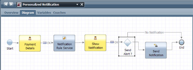
To add a Decision service to the Personalized Notification process, complete these steps:
- Create a new Decision service called NotificationRulesService.
- In the Library panel on the left side of the Process Designer window, move the mouse cursor over the Decisions item in the list of library items for the process application.
- Click the plus sign next to Decisions to add a new Decision service.
- In the Create New window, click Decision Service.
- In the New Decision Service window, enter NotificationRulesService as the Decision service name, then click Finish.
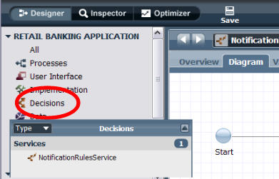 You can find more information about adding a Decision service in the related topic "Adding a Decision service to a process."
- Add a BAL Rule component called AlertRules to the NotificationRulesService Decision service.
- Make sure that you are editing the NotificationRulesService Decision service.
- Click BAL Rule in the component palette and drag the BAL Rule component icon from the palette to the service diagram.
- In the Properties tab, enter AlertRules ad the name for the new BAL Rule component.
- Click Save, or use the Ctrl+S keyboard shortcut to save the Decision service.
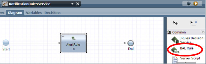 You can find more information about adding a BAL rule component in the related topic "Adding a BAL Rule component to a service."
- Create a business object called CheckingAccount that contains parameters such as CustomerName, Balance and Payments.
- Add a business object from the Process Designer library panel.
- Click the indicator next to the process application name in the library panel to see the categories of library items in the current process application.
- Click the plus sign next to the Data library item.
- In the Create New window, click Business Object.
- In the New Business Object window, enter CheckingAccount as the name for the business object, then click Finish.
- In the Behavior section of the Business Object panel, select Complex Structure Type as the Definition Type.
- Add parameters to the CheckingAccount business object.
- In the Parameters section of the Business Object panel, click Add.
- In the Parameter Properties section, add the CustomerName parameter with the variable type set to String, the Balance parameter with the variable type set to Decimal, and the PastPayment parameter with the variable type set to Payment.
- Click Save, or use the Ctrl+S keyboard shortcut to save the Decision service.
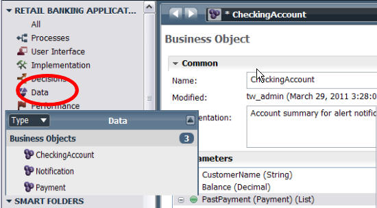 You can find more information about creating a business object in the related topic "Adding variable types and business objects to a Decision
service."
You can find more information about creating a business object in the related topic "Adding variable types and business objects to a Decision
service."
- Add a business object from the Process Designer library panel.
- Define which of the parameters are used as input variables to the Decision service, such as CustomerName, Balance and PastPayment,
and which parameters are output variables from the Decision service, including the notification message.
- Make sure you are editing the NotificationRulesService Decision service.
- Click the Variables tab.
- Click Add Input to add the input variables:
- In the Details section, enter accountIn as the name for the input variable.
- Click Select next to Variable type and click CheckingAccount in the list.
- Click the plus sign next to accountIn in the Variables list to confirm that CustomerName, Balance and PastPayment are included in the list.
- Click Add Output to add the output variable, notificationOut.
- In the Details section, enter notificationOut as the name for the output variable.
- Click Select next to Variable type and click Notification in the list.
- Click the plus sign next to notificationOut in the Variables list to confirm that message is included in the list.
- Click Save, or use the Ctrl+S keyboard shortcut to save the Decision service.
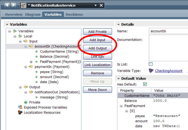 You can find more information about defining Decision service variables in the related topic "Adding and modifying Decision service variables."
- Use the BAL Rule editor to create rules in the AlertRules
BAL Rule component.
- Make sure you are editing the NotificationRulesService Decision service.
- Click the Diagram tab, then click to select the AlertRules BAL Rule component.
- Click the Decisions tab. By default, the rule editor opens with an empty BAL rule window. The rule window contains a basic template for a simple rule, with one condition (if) and one action (then).
- Click inside the rule window to begin creating a new rule from the template.
- Click the condition placeholder, next to if, to use the Content Assist menu to complete the condition. Add the following condition statements by double-clicking on each as it appears in the list. If the list closes before you can select a condition statement,
press Shift+Spacebar to reopen the Content Assist menu.
- if the amount of
- paymentIn
- is more than
- the balance of
- accountIn
The first part of the rule (if) looks like this:
- if the amount of paymentIn is more than the balance of accountIn
- Click the condition placeholder, next to if, to use the Content Assist menu to complete the condition. Add the following condition statements by double-clicking on each as it appears in the list. If the list closes before you can select a condition statement,
press Shift+Spacebar to reopen the Content Assist menu.
- Click the action placeholder next to then and add the following condition statements.
- set the message of
- notificationOut
- to
- string
When you double-click to select string, the edit cursor appears between two double quotation marks. Type the notification message, Payment takes account overdrawn between the double quotation marks.
The second part of the rule (then) looks like this:
then set the message of notificationOut to
 "Payment takes account overdrawn";
- Add a second rule editor window. Click the plus sign in the upper right corner of the BAL rule editor panel. Repeat the previous sequence of steps to create a second rule that looks like this:
if there is no payment in the past payments of accountIn
 where the payee of this payment is the payee of paymentIn ,
then
set the message of notificationOut to the message of notificationOut + "\n" +
 "Payment to new payee: " + the payee of paymentIn ;
- Click Save, or use the Ctrl+S keyboard shortcut to save the Decision service.
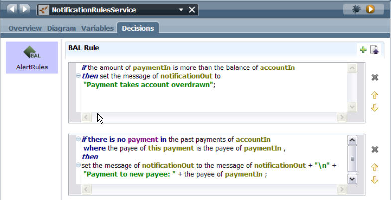 You can find more information about using the BAL Rule editor in the related topic "Creating a rule using the rule editor."
- Attach the NotificationRulesService Decision service to the Send Alert decision gateway.
- Make sure you are editing the NotificationRulesService Decision service.
- In the business process definition diagram, click the Send Alert decision gateway icon to select the decision gateway.
- Click the Properties tab.
- Click Decision.
- In the Decision Service section, click Select. Click to select the NotificationRulesService Decision service.
- Click Implementation in the Properties tab.
- Under the Decisions heading, add a variable statement to each decision to control the output of the decision gateway.
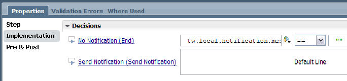 You can find more information about decisions in the implementation of a gateway, and attaching a Decision service to a gateway, in the related topic "Attaching a Decision service to a decision gateway."
- Test the Decision service and the BAL rules that you created and attached to the decision gateway.
- Make sure that you are editing the NotificationRulesService Decision service and the AlertRules BAL Rule component.
- In the NotificationRulesService Decision service, click to select the Send Alert decision gateway.
- Set a breakpoint for the gateway. Set breakpoints at specific locations in the process where you want the process flow to pause during testing so that you can determine the status of the process, and identify any errors that might have occurred.
- In the AlertRules BAL Rule component panel, click the Debug
 icon in the banner above the rule editor windows.
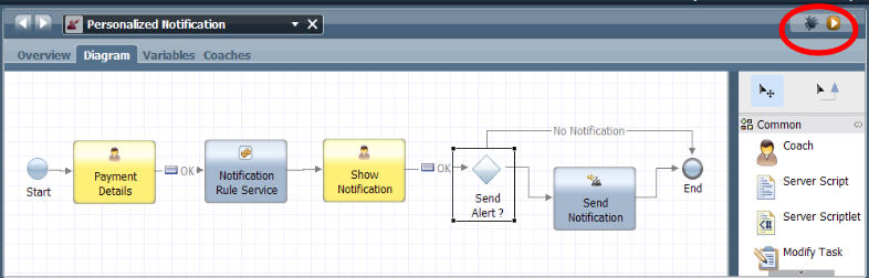
- The BPM Debug Service opens in a new browser window.
- When Process Designer prompts you to change to the Inspector interface, click Yes. The prompt to switch to the Inspector perspective might be covered up by the Debug window.
- Click Step in the Debug window to run the Decision service one step at a time. The Inspector clearly identifies any errors in the Execution State panel. The Inspector also tells you where the error happened, and links directly to the source of the problem. The Debug service browser window captures error and exception messages. For more information about using the Debug service and the Inspector window to identify and fix Decision service problems, refer to the related topic "Debugging a Decision service."
- If you make any changes to resolve errors in the Decision service or the BAL rules, click Save, or use the Ctrl+S keyboard shortcut to save the Decision service.
When you have finished creating, configuring and testing the AlertRules BAL rules in the NotificationRulesService Decision
service, then you have completed the scenario procedures. To create refine or share the rules that you create in Process Designer, you can export the rules into a project file and import them into IBM WebSphere ILOG JRules. For more information, refer to the related topic "Exporting, migrating and connecting BAL rules to a rule server."
Related tasks:
Add a Decision service to a process
Add a BAL Rule component to a service
Add variable types and business objects to a Decision service
Add and modifying Decision service variables
Create rules using the rule editor
Attaching a Decision service to a decision gateway
Scenario: Exporting rules to a Rule Execution Server
Add a Decision service to a process
You can add a Decision service to a business BPD. Use a Decision service when you want a decision or condition to determine which process implementation is invoked. For example, when a certain condition evaluates to true, Process Designer implements the associated activity or action.
- Open the process application that contains a BPD.
- Create a new Decision service.
- In the Library panel on the left side of the Process Designer window, move the mouse cursor over the Decisions item in the list of library items for the process application.
- Click the plus sign next to Decisions to add a new Decision service.
- In the Create New window, click Decision Service.
- In the New Decision Service window, enter a name for the new Decision service, then click Finish.
- Process Designer displays the diagram of the service with the default Start Event and End Event components.
- Drag a rule component, such as a BAL Rule, JRules Decision Service or Decision Table component, from the component palette to the Decision service diagram.
- Depending on which component or components you added to the service diagram, follow the additional steps in the following related topics to configure the components in the Decision service:
- Add a BAL Rule component to a service
- Add a JRules Decision Service component to a service
- Add a Decision Table component to a service
- Add a BAL Rule component to a service
You can now nest this Decision service in any other service within your process application that requires this logic. Be sure to adjust the input and output variables as required for each implementation. Refer to the related topic "Declaring and passing variables" for more information.
Related concepts:
Declaring and passing variables
Related tasks:
Scenario: Creating a Decision service in a Personalized Notification process
Add a BAL Rule component to a service
Add a JRules Decision Service component to a service
Add a Decision Table component to a service
Authoring rules using JavaScript in a Decision Table component
Implementing an activity using a Decision service
You can implement an activity using a Decision service.
To select a Decision service as the implementation for an activity:
- Open the business BPD diagram that contains that activity to implement using a Decision service.
- Click the activity in the diagram to select the activity.
- Click the Implementation option in the properties.
- Click the drop-down list and select Decision Task from the available options.
- Click the Select button to choose the Decision service that you want from the library. If the service does not yet exist, click the New button to create it.
Attaching a Decision service to a decision gateway
You can use a decision gateway in your business BPD when you need to model a point in the process execution where only one of several paths can be followed, depending on a condition. You can also attach a Decision service to a decision gateway.
When you attach a Decision service to a decision gateway, the process follows a specific sequence line coming out of the gateway based on the result of the conditions and actions in the rule components in the Decision service. If there are multiple decisions in the Implementation properties for the gateway, the decisions are evaluated from top to bottom and the path for the first decision that evaluates to true is followed. If no decisions evaluate to true, the default path is followed.
To attach a Decision service to a decision gateway:
- In the business process definition diagram, click the decision gateway icon to select the decision gateway where you want to attach the Decision service.
- Click the Properties tab.
- Click Decision.
- In the Decision Service section, click Select.
- Select the Decision service you want to attach to the gateway from the list of available services.
- If you decide not to use an existing Decision service, you can create a new service. Click New next to the Service field. You can remove an attached Decision service from a decision gateway. Click the delete icon (X) next to the Decision service name.
- The Inputs section contains a variable condition statement field that controls the behavior of the gateway, based on the result of the rules in the rule component.
- To select an input variable statement, click the variable icon
 to display a list of available variables.
- The Inputs section includes an auto-map function. To create a mapping between the variables used in the Decision service and the variables that are used in the main business process definition, click the auto-map icon
 .
.
When developing processes in BPM, you must set the input and output mapping for each activity included in a business process definition so the variable values received and generated by services map to the variables from the main process definition. For more information about the auto-map function, refer to the related topic "Mapping input and output data for an activity."
The text field under the Inputs heading shows the JavaScript object that represents the variable. The variable name is displayed to the right of the Inputs field.
- To select an input variable statement, click the variable icon
- Click Implementation in the Properties tab.
- Under the Decisions heading, add a variable statement to each decision to control the output of the decision gateway. The last decision is the default condition sequence line, which is followed if none of the decisions evaluate to true. You can change the position of a decision. Click the down arrow or the up arrow next to a decision to move it down or up in the decision list.
- For each decision above the last (default) decision, add an output variable statement. Click the variable icon to display a list of available output variables that are defined in the Decision service. The text field for each decision shows the JavaScript object that represents the variable condition.
- To enable the process to process the decision and choose the correct output sequence line for the decision gateway, also specify a comparison function and a value for each decision.
For example, if the purpose of the decision gateway is to determine whether a notification message is sent to a customer or not, then the decisions are No Notification (the process ends with no message sent), or Send Notification. The value of the No Notification decision
is null, because the rules in the decision service have determined that no notification message is required. The value of the Send Notification
decision is determined by variables that are defined in the rules.
In this example, Send Notification is the default decision. The example decisions are illustrated in the following figure:
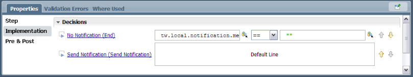 In this screen capture, the input variable tw.local.notification.message in the top position is set to no message as output; that is, no text will be sent as indicated by the quotation marks with no text inside (""). This output would be determined by the logic of the decision
service. Under a certain set of conditions, no message would be sent.
For example, if the decision service checked a database, and found the customer no longer existed it would not send a message. Another
possibility might be the customer had an invalid email address, so no message would be sent.The input variable and its output in the bottom position are hidden in this screen capture; however, by using the arrows you could move the bottom position up to the top position and the code would be displayed. This is the default output, which is to send a message. The message sent as output could be in quotation marks, for example, "Your order is confirmed," or the message sent as output might be in an another variable such as orderConfirmationNumber,
which would contain the order number for something the customer had ordered.
In this screen capture, the input variable tw.local.notification.message in the top position is set to no message as output; that is, no text will be sent as indicated by the quotation marks with no text inside (""). This output would be determined by the logic of the decision
service. Under a certain set of conditions, no message would be sent.
For example, if the decision service checked a database, and found the customer no longer existed it would not send a message. Another
possibility might be the customer had an invalid email address, so no message would be sent.The input variable and its output in the bottom position are hidden in this screen capture; however, by using the arrows you could move the bottom position up to the top position and the code would be displayed. This is the default output, which is to send a message. The message sent as output could be in quotation marks, for example, "Your order is confirmed," or the message sent as output might be in an another variable such as orderConfirmationNumber,
which would contain the order number for something the customer had ordered.
Related tasks:
Scenario: Creating a Decision service in a Personalized Notification process
Mapping input and output data for an activity
Add a BAL Rule component to a service
The Business Action Language (BAL) Rule component provides a rule editor that allows rule designers to author business rules using natural language technology. Using natural language, instead of JavaScript, to author rules means that no programming expertise is required to create business rules, and the rules are easier for people to read and understand. The following steps describe how to add a BAL Rule component to a sample Decision service. The purpose of the sample service is to determine whether approval is required for certain employee expenses. The sample service is a single-function Rule that can be called from any other service.
- Open the process application that contains a business process definition.
- Create a Decision service as described in the related topic "Adding a Decision service to a process."
- In the diagram of the new Decision service, click BAL Rule in the component palette and drag the BAL Rule component icon from the palette to the service diagram.
- In the Properties tab, enter a name for the new BAL Rule component, such as ExpenseApproval.
- Click the Variables tab.
- Click Add Private to add a private variable to the Decision service. For this sample Decision
service, add the private variable, request.
- Replace Untitled1 in the Name field with request .
- Click Select next to Variable Type and select the type from the list.
- If using the Activity Wizard to create a Decision service, you can choose existing variables to add as input and output. You should use the Activity Wizard when you start with an existing activity and want to quickly create a service to implement the activity. To access the wizard, right-click an activity icon in a process diagram and select Activity Wizard from the list of options.
- Click Add Private.
- Replace Untitled1 in the Name field with approvalRequired .
- Click Select next to Variable Type and select the Boolean type from the list. The Boolean variable type is included in the BPM System Data toolkit. The System Data toolkit is included in each process application by default.
- Click the Decisions tab to open the rules editor.
Create a rule that is implemented for this Decision service.
Refer to the related topic "Authoring rules using the BAL rule editor."
- Create rules using the rule editor You can create rules using the Business Action Language (BAL) rule editor. The rule editor uses natural language technology to express business decisions in a form that is readable by humans but can also be run by a rule service runtime such as the JRules Rule Execution Server.
- Business rule parts and structure Business rules, such as action rules or decision tables, express business policy statements using a predefined business vocabulary that can be interpreted by a computer. Rules authored in the Business Action Language (BAL) are also easily readable by humans.
- Defining variables in the rule editor Variables are defined in the definitions part of a business rule.
- Copying and pasting content in the rule editor You can copy content from a rule to the system clipboard, or paste content written outside the rule editor into the editor window.
- Set the rule language You can use the locale preference setting provided in Process Designer to set the language used in a BAL Rule component.
- Troubleshooting BAL rule editor errors The Business Action Language (BAL) rule editor highlights errors with red underline in the editing window.
Related tasks:
Scenario: Creating a Decision service in a Personalized Notification process
Declaring variables for a BPD or a service
Authoring rules using the BAL rule editor
Add a Decision service to a process
Create rules using the rule editor
Create rules using the rule editor
You can create rules using the Business Action Language (BAL) rule editor. The rule editor uses natural language technology to express business decisions in a form that is readable by humans but can also be run by a rule service runtime such as the JRules Rule Execution Server. You can use the BAL rule editor to build rules, add rule parts, statements, and fragments, and replace placeholders with variables and values. Use the completion menu in the editor to insert or edit constants, values, parts, or fragments of rule statements. While you are creating or editing rules, the editor highlights errors to help you identify and resolve problems in your rules.
A business rule consists of some or all of the following parts. The parts must be defined in the following order:
- definitions part (optional)
- if part
- then part
- else part (optional)
For more information about the parts and structure of a business rule, refer to the related topic "Business rule parts and structure."
The following steps describe how to author a rule using the rule editor. The rule is implemented in a BAL Rule component as part of a sample Decision service. The purpose of the sample service created in the procedure steps is to determine whether approval is required for certain employee expenses. The sample service is a single-function rule that can be called from any other service.
- Make sure you are working in the sample Decision service that was created in the related topic "Adding a BAL Rule component to a service."
- Click the Decisions tab to open the rule editor.
- By default, the rule editor opens with an empty BAL rule window. The rule window contains a basic template for a simple rule, with one condition (if) and one action (then).
- Click inside the rule window to begin creating a new rule
from the template.
- Click the condition placeholder, next to if, to use the Content Assist menu to complete the condition. Double-click
a condition statement in the menu to add that condition to the rule.
- If the list of conditions is long, you can use the Tree Completer menu instead of the Content Assist menu to select the condition statement. With the edit cursor on the <condition> placeholder, press Ctrl+Shift+Spacebar to open the Tree Completer menu.
- If you know the name of the condition you want to insert, start typing the condition name. The Tree Completer shows all the conditions that match the name as you type, as shown in the following diagram:
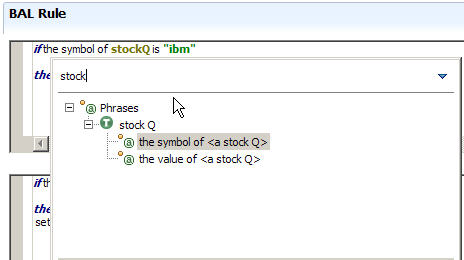
- Click the action placeholder, next to then, to select from the menu of possible actions. Double-click an action statement in the menu to add that action to the rule. For more information about using the menu to select actions, refer to the related topic in the IBM WebSphere ILOG JRules InfoCenter, "Inserting a term or a phrase."
- Click the condition placeholder, next to if, to use the Content Assist menu to complete the condition. Double-click
a condition statement in the menu to add that condition to the rule.
- To add additional rule parts to the rule, click to place the editor cursor above or below the existing rule content, then press Ctrl+Spacebar to activate the Content Assist menu. The Content Assist box displays a list of valid rule parts. For example, to create a definition rule part, click before the if condition section, then press Ctrl+Spacebar to open the Content Assist menu and select definitions. To create an else rule part, click below the then section of the rule.
- To add additional rules to the BAL Rule component, click the plus symbol at the top of the rule editor window. Each time you click the plus symbol, a rule editor window is opened. Each window contains the simple rule template.
- In a BAL Rule component that contains multiple rules, you can change the order of the rules. Click the up arrow beside the editing window to move the rule up one place in the rule order. Click the down arrow to move the rule down one place in the rule order.
- The rule editor saves the rules periodically as you are authoring. To save all the rules in the BAL Rule component while you are authoring, click Ctrl+S, or click the Save icon in the Process Designer action bar.
- To exit the rule editor, click the exit icon (X) next to the Decision service name.
Related concepts:
Business rule parts and structure
Related tasks:
Scenario: Creating a Decision service in a Personalized Notification process
Add a BAL Rule component to a service
Business rule parts and structure
Business rules, such as action rules or decision tables, express business policy statements using a predefined business vocabulary that can be interpreted by a computer. Rules authored in the Business Action Language (BAL) are also easily readable by humans.
For example, the business policy "refuse a loan to customers whose credit score is below the minimum of 200" can be expressed as a business rule in the following way:
- definitions
- set minimum_score to 200;
- if
- the credit score of the borrower is less than minimum_score
- then
- refuse the loan with the message "Credit score below" + minimum_score;
The parts must be defined in the following order:
- definitions part
- if (conditions) part
- then (actions) part
- else (optional actions) part
Definitions
The definitions part of a rule gives you more control over your business rules when you set variables at the beginning of your rule. Variables help you identify and then reference an occurrence of a business term by a convenient name. Use variables to make your business rules less ambiguous and easier to understand.
Define a variable by giving it a name of your choice and then setting a value for the variable. This value can be a number (or an arithmetic expression whose result is a number), text, or a predefined business term that already exists in your rule ( customer). Once you have set a variable, it becomes available in all the parts of the current rule. The variable is valid only in the rule in which it is defined.
The simplest use of definitions is to define a constant value that you can use throughout your rule. For example, by declaring a variable called minimum_score in the example rule, you make the rule easier to understand:
- definitions
- set minimum_score to 200;
This is a very basic illustration of the definitions part of a rule. For more information about complex versions of the definition part, such as multiple occurrences of a value, or adding a where clause to a definition to apply further restrictions on the variables, refer to the related section in the WebSphere ILOG JRules InfoCenter, "Understanding your rules -- Definitions." A related link is provided.
Conditions
The condition part of a rule specifies under what conditions the actions in the action part of the rule will be carried out. Conditions are represented in the rule editor by the text (or number) that appears after if, ending at then. The word then signals the beginning of the action part of the rule.In the example rule, the condition is defined so that when the credit score of the borrower is below the minimum value, then the loan to the customer is refused.
- if
- the credit score of the borrower is less than minimum_score
Actions
The action part of a rule describes what to do when the conditions of the rule are met. Actions are represented in the rule editor by the text that appears after then and else. If there is more than one action to perform, the actions are carried out in the order they appear in the action part of the rule.In the example rule, the action is defined so that when the condition evaluates to true, then the resulting action is to refuse the loan, and issue a message "Credit score below 200."
- then
- refuse the loan with the message "Credit score below" + minimum_score;
Optionally, you can include an else part in a rule. The else part of a rule is an optional block of actions that specify what to do when the conditions are not met. You can use an else rule part in combination with variables in the definitions part to control the rule action more precisely. If a rule contains both definitions and a condition part, the else part of a rule will only be run if the conditions set in the variables are satisfied and the condition part of the rule is not satisfied. This sample rule shows this application for the else part:
- definitions
-
set applicant to a customer; where the category of this customer is Gold;
- if
- the value of the shopping cart is more than $100
- then
- apply a 15% discount
- else
- apply a 5% discount;
Related tasks:
Create rules using the rule editor
Understanding your rules: Definitions
Understanding your rules: Conditions
Understanding your rules: Actions
Defining variables in the rule editor
Variables are defined in the definitions part of a business rule.
Variables are accessible from business rules when you add them to the rule vocabulary. For more information about verbalizing variables, refer to the related topic "Adding and modifying Decision service variables."
You can use a variable to identify and then refer to an occurrence of something by a convenient name. Use variables to make your business rules clear and easy to understand. When you create a variable in a rule, the variable is only valid for that rule, although the variable can be used in a all parts of the rule. Variable names must be unique within a rule.
To define a variable, complete these steps:
- In the definitions part of the rule, press Ctrl+Spacebar, and double-click to select set from the Content Assist menu. The content of the Content Assist menu changes to show the default name for new variables, variable1. After the definitions are specified, the Content Assist menu changes to show the closing semicolon.
- Double-click in the Content Assist menu to insert the placeholder variable name variable1 in the rule.
- Type over the placeholder variable name to replace variable1 with the name of your variable. If your variable is only one word, quotation marks are not required. If your variable is a phrase containing more than one word, you must put the phrase between quotation marks.
- Press Ctrl+Spacebar, and select a variable type from the menu. In BPM, every variable name is associated with a variable type, which determines what values are legal for the associated variable. For more information, refer to the related topic "Variable types."
- After the variable type is specified, the Content Assist menu changes to show the closing semicolon, or the optional building blocks from, in, and where. If you have finished defining the variable, select the closing semicolon. To define a variable using the optional building blocks, continue by selecting from, in, or where.
- The variable definition ends with the closing semicolon. Once a variable is defined, you can use the variable in all parts of the business rule.
Example
To make a rule easier to read, you can use a variable to define a one-to-one relationship between business objects. In the following business rule, the variable the shopping cart is defined using the one-to-one relationship between two objects: the ShoppingCart and the Customer:- definitions
-
set customer to a customer; set the cart to the shopping cart of customer;
- if
- the value of the cart is less than $100
- then
- apply 10% discount;
You must initialize complex variable structures before running the Decision service. In BPM, all complex variables and all lists (arrays) must be initialized before use them in a BPD or service. If you do not initialize a complex variable or list, you may receive runtime errors or notice the controls to which the variables are bound do not behave as expected. For more information, refer to the related topic, "Initializing complex variables and lists."
Related concepts:
Copying and pasting content in the rule editor
You can copy content from a rule to the system clipboard, or paste content written outside the rule editor into the editor window.
To cut or paste content in the rule editor:
- You can copy the contents of an individual rule to the system clipboard.
- Click to place the edit cursor inside the rule that contains the rule content you want to copy.
- Highlight the content you want to copy. To select the entire content of the rule, press Ctrl+A.
- Copy the content to the clipboard using a keyboard shortcut,
or the product menu, or the right-click menu, as described in the following steps:
- Press the copy keyboard shortcut for your system. For example, on a Microsoft Windows system, the copy function shortcut is Ctrl+C.
- From the main product menu, click Edit > Copy.
- Right-click in the rule editor window and select Copy from the menu.
- Press the copy keyboard shortcut for your system. For example, on a Microsoft Windows system, the copy function shortcut is Ctrl+C.
- To paste content from the system clipboard into a rule, complete these steps.
- Verify the content you want to paste into the rule has been copied into your system clipboard.
- Click to place the edit cursor inside the rule in the location where you want the pasted content to appear.
- Paste the content to the rule editor window using a keyboard shortcut, or the product menu, or the right-click menu, as described in the following steps:
- Press the paste keyboard shortcut for your system. For example, on a Microsoft Windows system, the paste function shortcut is Ctrl+V.
- From the main product menu, click Edit > Paste.
- Right-click in the rule editor window and select Paste from the menu.
- Press the paste keyboard shortcut for your system. For example, on a Microsoft Windows system, the paste function shortcut is Ctrl+V.
Set the rule language
You can use the locale preference setting provided in Process Designer to set the language used in a BAL Rule component.
The BAL Rule component language is set to English by default, but you can change the locale setting to change the language used in new BAL Rule components. Once the locale is set, you can create new BAL Rule components using the updated locale. However, if you add new rules to an existing BAL Rule component that was created before you changed the locale, the added rules use the locale setting from the BAL Rule component, not the updated locale preference setting.
To change the locale setting:
- From the main menu, click File > Preferences
- Click BPM to display the available options.
- Click Rules.
- Click English next to BAL Decision Locale, then select a language from the menu.
Troubleshooting BAL rule editor errors
The Business Action Language (BAL) rule editor highlights errors with red underline in the editing window.
To identify and correct an error in a rule, use the mouse to hover over the highlighted error in the editor. When the error tip window is displayed, click the underlined text in the error to go to the location of the error. Type in the editing window to correct the error.
Error indicators in the rule editor
Errors in the rule editor are indicated by a wavy line under the section of the rule that is invalid. Errors are underlined in red. Warnings are underlined in yellow.

Use Quick Fix to identify and fix errors
The Eclipse Quick Fix feature is available in the BAL rule editor. Quick Fix messages offer suggestions to help you correct rule errors.
To see a proposed Quick Fix, click the light bulb icon next to the error indicator in the rule editor window, or place your cursor on the error and press Ctrl+1.The messages provide a list of possible corrections from which you can select the appropriate fix.
To auto-correct an error from the quick fix message:
- Put your cursor on the error indicator to display the error messages.
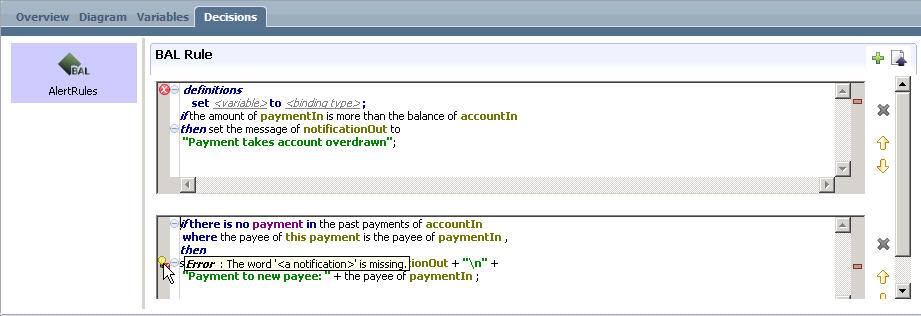
- Click the light bulb icon or move your cursor to the error in the rule, and press Ctrl+1 to open the Quick Fix message.

- From the list of suggestions, click to select the appropriate fix.
Add and modifying Decision service variables
Each IBM Business Process Manager Decision service has a set of input, output, and private variables that are declared for that service. The business terms and phrases that you define as variables are available for you to use when you are writing rules. For example, the variable appear in the Content Assist menu in the rule editor.
A Decision service might require input or output variables, or both. A service can also include private variables for processing that occurs only within the service. For more information about variables in a Decision service, refer to the related topic "Declaring variables for a service."
To add or modify variables for a Decision service:
- Make sure you have selected the Decision service where to add or modify variables.
- Click the Variables tab.
- Existing variables are organized into three sections: Input,
Output, and Private. Click the plus sign next to a section to see the variables in that section.

- You can add a variable to the Decision service by completing one of the following steps:
- Click Add Input to add a variable that you can use for input into a rule.
- Click Add Output to add a variable that you can use for output from the rule.
- Click Add Private to add a variable that applied only to the current Decision service.
The following information applies to variables:
- Variables are mapped to the IN, OUT or IN-OUT parameter directions automatically, depending on how the variable is used in the rule. For example, a variable that is referenced in a rule but is not updated at run time is identified as an IN variable. For more information about parameters, refer to the related topic "Adding variable types and business objects to a Decision service."
- The input or output designation for variables might affect the way the Decision service runs, but the designation is not significant when you are authoring BAL rules because input, output and private variables are all referenced identically in a BAL rule.
- If you create an input and an output variable that have the same name, only one variable is actually created. The variable is used for both input and output at the Decision service level.
- Exposed Process Variables (EPVs) are managed at the process application level, and allow the BPM administrator to specify designated users who can set or alter variable values using the Process Admin Console while instances of a process are running. The Decision service can pick up an EPV variable that has been created in a process application and use the variable in a rule to affect the way the Decision service runs. For more information about EPVs, refer to the related topic "Creating exposed process values."
- You can modify or view the properties of an existing variable. Click to highlight the variable name, then modify the variable properties under the Details section, or view the Default Value of the variable if a default value has been defined:

- Select an existing Variable Type,
or define a new variable type.
- Click Select to set or modify the current variable type.
- Click New to define a new variable type. For more information about defining a new variable type using the Business Object editor, refer to the related topic "Adding variable types and business objects to a Decision service."
You must initialize private variables before running the Decision service. In BPM, all private variables must be initialized before use them in a business process definition or Decision service. If you do not initialize a variable, you may receive runtime errors or notice the controls to which the variable is bound do not behave as expected. For more information, refer to the related topic, "Initializing complex variables and lists."
- Default rule variables and parameters Pre-defined variables and variable types are deployed from the System Data toolkit when BPM is installed.
- Add variable types and business objects to a Decision service In IBM Business Process Manager, you can create a custom business object (variable type) for the Decision service. The variable type becomes part of the data for the process application, and is available for all business process definitions (BPDs) and services included in the process application.
- Variable types You can define a Decision service variable by first specifying the name of the variable, then setting the variable type. The variable value can be a simple data type such as a string, integer, or date. You can also define a complex variable type using a business object that contains parameters.
Related tasks:
Scenario: Creating a Decision service in a Personalized Notification process
Add variable types and business objects to a Decision service
Default rule variables and parameters
Pre-defined variables and variable types are deployed from the System Data toolkit when IBM Business Process Manager is installed.
Default Decision service variables
The System Data toolkit is imported into the Process Center repository so that each process application and toolkit that you create has access to BPM system data. The System Data toolkit includes assets that all BPM projects require, including variable types. The Decision service can use most of the pre-defined variables and variable types, with a few exceptions.
For example, when you create a new variable in the Rule editor, and select a business object (variable type) to associate with the variable, the following list of default variable types is displayed:

The following variable types are not supported for Decision service variables:
- SQLResult
- XMLDocument
- XMLElement
- XMLNodeList
Decision service parameters
Decision service parameters, which are defined for each business object (variable type) provide a mechanism for exchanging data between a rule component and a process application. You can define Decision service parameters using the following elements:
- A business object name
- A variable type
- A direction, which indicates whether a parameter is used as input to a Decision service, or output from the Decision service, or both. The direction setting is determined automatically based on how the parameter or variable is used in the rule. For example, any parameter or variable that is referenced in a rule, but is not modified or updated when the service is running, is identified as an IN variable.
For information about setting up Decision service parameters, see the related topic "Adding variable types and business objects to a Decision service."
Related tasks:
Add variable types and business objects to a Decision service
Add variable types and business objects to a Decision service
In IBM Business Process Manager, you can create a custom business object (variable type) for the Decision service. The variable type becomes part of the data for the process application, and is available for all business process definitions (BPDs) and services included in the process application.
To create a custom business object (variable type), you must have write access to a process application or toolkit in the Process Center repository. Access to process applications and toolkits is controlled by users who have administrative rights to the repository.
To add a business object (variable type) to a Decision service, complete these steps:
- You can add a variable type from the Process Designer library panel, or from the Variables tab while you are working in the Rule
service.
- To add a business object from the Process Designer library panel:
- Click the indicator next to the process application name in the library panel to see the categories of library items in the current process application.
- Click the plus sign next to the Data library item.
- In the Create New window, click Business Object.
- In the New Business Object window, type a name for the variable type, then click Finish.
- Follow the procedure steps to define the new business object (variable type).
- To add a variable type while working in the Decision service:
- Make sure you are working in the Decision service where to add the new variable type.
- Click the Variables tab.
- Create a new variable, or select the variable where to add the new variable type. For more information about adding variables, refer to the related topic "Adding and modifying Decision service variables."
- In the Details section, click New next to the Variable Type field.
- In the New Business Object window, type a name for the variable type, then click Finish.
- Follow the procedure steps to define the new business object (variable type).
- To add a business object from the Process Designer library panel:
- In the Behavior section, select a Definition Type from the list.
- Select Simple Type to create a new variable type using an existing type such as String, Decimal, or Integer. For more information about creating simple variable types, refer to the related topic "Creating custom variable types."
- Select Complex Structure Type to create a new complex variable type. You can create a custom variable type by adding parameters and parameter properties to the business object.
For more information about creating complex variable types, refer to the related topic "Adding process variables to a BPD."
As you are adding parameters for a complex structure type, you can see the resulting changes to the XML schema for the variable type. To see how the variable parameters are declared in the XML schema, open the Advanced Properties section and click View XML Schema.
- When you have entered all the necessary parameters and settings for the variable type, click Save in the main toolbar.
- Return to the Decision service editing panel, then click Select next to the Variable Type field. The variable type that you added is listed as an available type.
In BPM,
all complex variables must be initialized before you can use the variables in a BPD or service. Refer to the related topic "Initializing complex variables and lists" for more information.
Related concepts:
Default rule variables and parameters
Related tasks:
Scenario: Creating a Decision service in a Personalized Notification process
Add and modifying Decision service variables
Declaring variables for a BPD or a service
Variable types
You can define a Decision service variable by first specifying the name of the variable, then setting the variable type. The variable value can be a simple data type such as a string, integer, or date. You can also define a complex variable type using a business object that contains parameters.
Declaring the variables for a service enables the service to display and manipulate the values that it receives from (input) and then pushes back up (output) to the main business process.
You must initialize complex variable structures before running the Decision service. In BPM, all complex variables and all lists (arrays) must be initialized before use them in a business process definition or service. If you do not initialize a complex variable or list, you may receive runtime errors or notice the controls to which the variables are bound do not behave as expected. For more information, refer to the related topic "Initializing complex variables and lists."
Complex variables for hierarchical data
In IBM Business Process Manager, you can create a custom variable type by using a base variable type or by defining a new complex structure. You can create rules about complex data that is nested, or hierarchical. Data that is referenced within the text of a rule is not limited to simple data types such as string, integer, or date. You can create complicated rules with nested variable structure. For example, in the Decision service shown in the following diagram, the variable paymentIn has the variable type Payment, and contains other, nested variables.
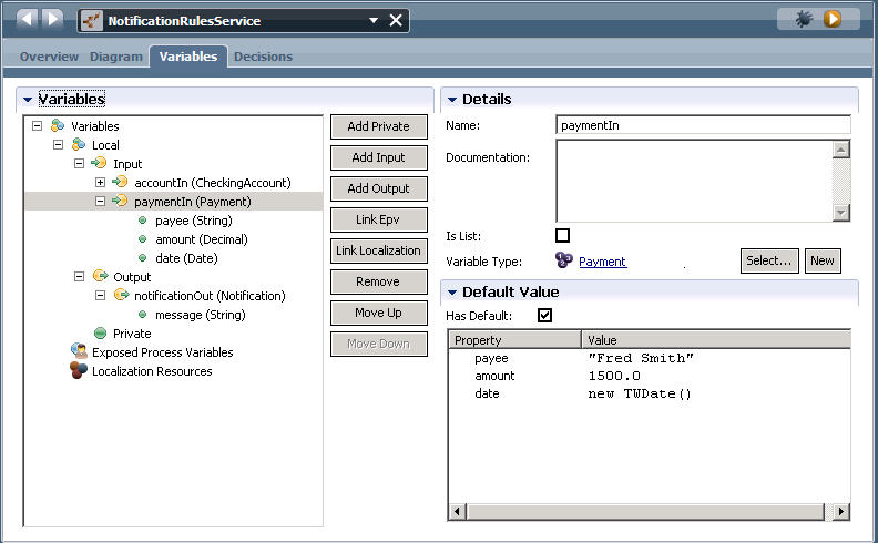
For more information about creating complex, hierarchical variable types, see the related topic "Adding process variables to a BPD."
There are several complex variable types that are not supported when authoring rules in a Decision service. The unsupported variable types are:
- SQLResult
- XMLDocument
- XMLElement
- XMLNodeList
Collections (lists) of variables
You can write rules against collections, or lists of variables, using Business Action Language (BAL) rule constructs. You can use a variable to retrieve a collection (list) of objects of a specific type. Use a list parameter in a business object when then are numerous objects that your rule must run against, instead of just a single object. For example, if you are writing a rule about an invoice, and there are multiple line items in the invoice, then the invoice is actually a collection of line items. To write a rule against the number of line items (if there are 10 or more line items, then process this invoice manually), add a list parameter in a complex variable to your rule.
In the complex variable type, or business object, shown in the following diagram, PastPayment is a list parameter, which means that it contains multiple objects of the String, Decimal and Date variable type. To identify a variable as a collection or list, click to select the Is List option under Parameter Properties.

Predefined variable types
Many pre-defined variable types are provided by the BPM System Data toolkit. These variables are defined as business objects. You can open a business object in Process Designer and review the Documentation field to learn when and how to use each variable type. For example, to open the Record business object included in the System Data toolkit, complete these steps:
- Open a process application in Process Designer.
- Click the indicator next to the Toolkits category to see a list of toolkit dependencies for the current process application.
- Click the indicator next to the System Data toolkit to see its contents.
- Click the Data category
- Double-click the Record business object to open it. The Documentation field provides information about the business object. The documentation informs you that a Record is a group of ANY typed variables and that you do not need to declare the number of ANY typed variables to go into the Record. So, the Record object is similar to a Structure object, except you do not need to declare the type or the number of variables it contains.
For additional information about using variable types in rules, refer to the related topic "Types of variable definition" in the WebSphere ILOG JRules InfoCenter.
Related tasks:
Defining variables in the rule editor
Declaring variables for a BPD or a service
Testing a Decision service
When you have finished creating a Decision service and authoring rules in a rule component, such as a BAL Rule component, you can test the Decision service to determine if the rules are being applied as you intended. If an error or exception occurs within a rule, you will see messages about the error during testing, and you can debug the specific rule component or rule that caused the error.
To test a rule component and the rules it contains, you can load the Decision service with default data and then step through the activities in your business process definition to see the generated process data as it interacts with the business rules you have defined. For example, if you set a breakpoint on an activity that has an associated Decision service, you can make sure the Decision service is producing the data you expect, and make sure there are no error messages or exceptions being produced by the Decision service as it runs.
To test a Decision service, complete these steps:
- Make sure that you are working in the business process definition that contains the Decision service you want to test.
- Click to select the activity or decision gateway in the business process that has the Decision service associated with it.
- Set a breakpoint in the activity. Set breakpoints at specific locations in the process where you want the process flow to pause during testing so that you can determine the status of the process, and identify any errors that might have occurred.
- Click the Decision service name to open the rules in the rule editor.
- Click the Run service icon
 in the banner above the rule editor.
- When Process Designer prompts you to change to the Inspector interface, click Yes. The Inspector displays red tokens both in the BPD diagram and the execution step tree, which provides a hierarchical view of the execution state, showing the step that is currently running in the active process instance.
- Debugging a Decision service Debug a rule component in a Decision service using the Inspector perspective and the debugging feature in Process Designer. Use these testing functions to can examine how the Decision service operates in each step of the process execution, which provides a more detailed inspection than simply stepping through the process.
- Exception messages in Decision service testing You can review exception messages that result from Decision service testing. The exceptions provide information that is helpful when you are troubleshooting Decision service execution errors.
Related tasks:
Scenario: Exporting rules to a Rule Execution Server
Debugging a Decision service
Debug a rule component in a Decision service using the Inspector perspective and the debugging feature in Process Designer. Use these testing functions to can examine how the Decision service operates in each step of the process execution, which provides a more detailed inspection than simply stepping through the process.
There are several types of Decision service problems that you can troubleshoot using the Debug Service and the Inspector. For example:
- Results from running the Decision service are not what you expected.
- Run the Decision service results in an exception and you need to identify the process step that generates errors.
To enable the Debug Service to step through the Decision service execution, set a breakpoint on each activity within the Decision service before running the debug function.
- Make sure that you are working in the Decision service to test and debug.
- Click the Debug
 icon.
icon.
- The BPM Debug Service opens in a new browser window, as shown in the following diagram:

- Click Step in the Debug window to run the Decision service one step at a time, or click Run to run the complete Decision service.
- When Process Designer prompts you to change to the Inspector perspective, click Yes.
The prompt to switch to the Inspector perspective might be covered up by the Debug window.
- The Inspector opens the currently running service in the Services in Debug tab and shows progress through the service, using a hierarchical tree in the Execution State panel to show the process step running.
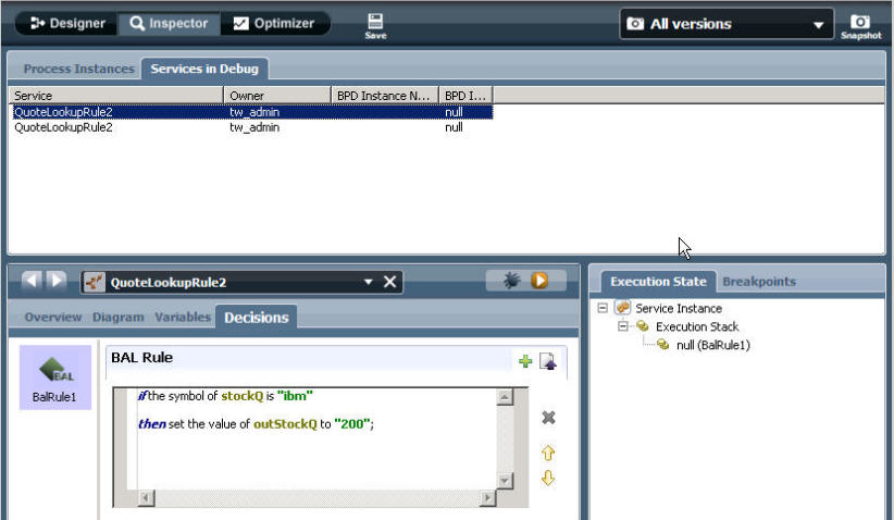
- When you run a Decision service and an exception occurs, the Inspector clearly identifies the error in the Execution State panel. The Inspector also tells you where the error happened, and links directly to the source of the problem. For more information about using the Inspector to debug errors, see the related topic "Resolving errors."
- The Debug service browser window captures error and exception messages. The first few lines of the exception are displayed at the top of the browser window. To see the complete message, click Details. To help you locate the rule that produced the error, some exception messages refer to specific rules by their order number, such as Rule
1, Rule 2, Rule 3, prefixed by the name of the Decision service step,
as shown in the following example:
An error occurred in QuoteLookupRule2 service, at step BalRule1.
   Detail message: Object stockQ not found at run time during execution.
   You must make sure the object has been initialized.
Related tasks:
Scenario: Creating a Decision service in a Personalized Notification process
Exception messages in Decision service testing
You can review exception messages that result from Decision service testing. The exceptions provide information that is helpful when you are troubleshooting Decision service execution errors.
When troubleshooting Decision service errors, the following information applies to the exception messages:
- When a rule component is running, exception messages include the Decision service name and step name.
- Exceptions in a rule condition cannot be traced to a specific rule.
- Exceptions in a rule action can be traced to a specific rule.
- The rule name includes a number part corresponding to the order of the rules in the BAL rules component, such as 1, 2, 3, or 4. If there are numerous rules in a BAL rules component, this number helps you track down the location of the error.
Example of a null exception
If a variable value cannot be resolved, this problem results in a null exception:ilog.rules.res.session.IlrRuleServiceException: ilog.rules.res.session.IlrSessionException: An error occurred while the rule session was invoked.:
ilog.rules.res.session.IlrSessionException: An error occurred while the rule session was invoked.
ilog.rules.res.util.IlrRemoteException: Ruleset execution error ilog.rules.res.util.IlrRemoteException: null at call to 'mainRuleflow flow task body'
at call to 'execute'
ilog.rules.res.util.IlrRemoteException
at ilog.rules.res.session.IlrRuleService.executeRuleset(IlrRuleService.java:124)
at com.ibm.rules.sdk.samples.documentrules.ResultsTab$4.widgetSelected(ResultsTab.java:206)
at org.eclipse.swt.widgets.TypedListener.handleEvent(TypedListener.java:234)
at org.eclipse.swt.widgets.EventTable.sendEvent(EventTable.java:84)
at org.eclipse.swt.widgets.Display.sendEvent(Display.java:3776)
at org.eclipse.swt.widgets.Widget.sendEvent(Widget.java:1367)
at org.eclipse.swt.widgets.Widget.sendEvent(Widget.java:1390)
at org.eclipse.swt.widgets.Widget.sendEvent(Widget.java:1375)
at org.eclipse.swt.widgets.Widget.notifyListeners(Widget.java:1187)
at org.eclipse.swt.widgets.Display.runDeferredEvents(Display.java:3622)
at org.eclipse.swt.widgets.Display.readAndDispatch(Display.java:3277)
at org.eclipse.ui.internal.Workbench.runEventLoop(Workbench.java:2629)
at org.eclipse.ui.internal.Workbench.runUI(Workbench.java:2593)
at org.eclipse.ui.internal.Workbench.access$4(Workbench.java:2427)
at org.eclipse.ui.internal.Workbench$7.run(Workbench.java:670)
at org.eclipse.core.databinding.observable.Realm.runWithDefault(Realm.java:332)
at org.eclipse.ui.internal.Workbench.createAndRunWorkbench(Workbench.java:663)
at org.eclipse.ui.PlatformUI.createAndRunWorkbench(PlatformUI.java:149)
at com.ibm.rules.sdk.samples.documentrules.Application.start(Application.java:38)
at org.eclipse.equinox.internal.app.EclipseAppHandle.run(EclipseAppHandle.java:196)
at org.eclipse.core.runtime.internal.adaptor.EclipseAppLauncher.runApplication(EclipseAppLauncher.java:110)
at org.eclipse.core.runtime.internal.adaptor.EclipseAppLauncher.start(EclipseAppLauncher.java:79)
at org.eclipse.core.runtime.adaptor.EclipseStarter.run(EclipseStarter.java:369)
at org.eclipse.core.runtime.adaptor.EclipseStarter.run(EclipseStarter.java:179)
at sun.reflect.NativeMethodAccessorImpl.invoke0(Native Method)
at sun.reflect.NativeMethodAccessorImpl.invoke(NativeMethodAccessorImpl.java:39)
at sun.reflect.DelegatingMethodAccessorImpl.invoke(DelegatingMethodAccessorImpl.java:25)
at java.lang.reflect.Method.invoke(Method.java:597)
at org.eclipse.equinox.launcher.Main.invokeFramework(Main.java:619)
at org.eclipse.equinox.launcher.Main.basicRun(Main.java:574)
at org.eclipse.equinox.launcher.Main.run(Main.java:1407)
at org.eclipse.equinox.launcher.Main.main(Main.java:1383)
Caused by: ilog.rules.res.session.IlrSessionException: An error occurred while the rule session was invoked.:
ilog.rules.res.session.IlrSessionException: An error occurred while the rule session was invoked.
ilog.rules.res.util.IlrRemoteException: Ruleset execution error ilog.rules.res.util.IlrRemoteException: null at call to 'mainRuleflow flow task body'
at call to 'execute'
ilog.rules.res.util.IlrRemoteException
Unsupported variable type
If you author a rule that uses an unsupported variable type, an exception message similar to the following example is displayed:An error occurred in simpleTypeTestService service, at rule 1 in step SimpleTypeRuleStep.
Detail message: Ruleset /b_c54531e1028c40a185bf1115183a3420/1.0/_bd1ea7af45d14fa9afcea38113db2c35_8cf262cc674e4561bce84c00820bc88e/1.0 parsing failed 'IRL/rule_1.irl', line 8:
error: incompatible values involved in assignments com.lombardisoftware.core.TeamWorksException:
An error occurred in simpleTypeTestService service, at rule 1 in step SimpleTypeRuleStep.
Detail message: Ruleset /b_c54531e1028c40a185bf1115183a3420/1.0/_bd1ea7af45d14fa9afcea38113db2c35_8cf262cc674e4561bce84c00820bc88e/1.0 parsing failed 'IRL/rule_1.irl', line 8:
error: incompatible values involved in assignments at com.lombardisoftware.core.TeamWorksException.asTeamWorksException(TeamWorksException.java:129)
at com.lombardisoftware.core.RegexExceptionRewriter.rewrite(RegexExceptionRewriter.java:76)
at com.lombardisoftware.core.ExceptionHandler.returnProcessedException(ExceptionHandler.java:310)
Uninitialized variable produces a NullPointerException
Use an uninitialized variable in a BPEL process can result in various exception errors. In BPM, all private or complex variables and all lists (arrays) must be initialized before use them in a business process definition or Decision service. If you do not initialize a private or complex variable or list, you may receive runtime errors, such as the following example, or notice the Coach controls to which the variables are bound do not behave as expected. For more information about errors produced by uninitialized variables, refer to the related topic "Uninitialized variable or NullPointerException in a Java snippet."An error occurred in NotificationRules service, at rule 1 in step AlertRuleStep. Detail message: Object CustomerName not found at run time during execution. Verify the object has been initialized. at com.lombardisoftware.core.TeamWorksException.asTeamWorksException(TeamWorksException.java:129) at com.lombardisoftware.core.RegexExceptionRewriter.rewrite(RegexExceptionRewriter.java:76) at com.lombardisoftware.core.ExceptionHandler.returnProcessedException(ExceptionHandler.java:310) at com.lombardisoftware.servlet.ControllerServlet.doError(ControllerServlet.java:152) at com.lombardisoftware.servlet.ControllerServlet.doCommon(ControllerServlet.java:417) at com.lombardisoftware.servlet.ControllerServlet.doPost(ControllerServlet.java:134) at javax.servlet.http.HttpServlet.service(HttpServlet.java:738) at javax.servlet.http.HttpServlet.service(HttpServlet.java:831)
Related reference:
Uninitialized variable or NullPointerException in a Java snippet
Scenario: Exporting rules to a Rule Execution Server
This scenario shows you how to export, migrate and connect BAL rules to a rule execution server (RES). You can migrate the rules that you created in Process Designer to a business rules management system (BRMS) such as IBM WebSphere ILOG JRules, and then continue to use the rules in a business process definition.
This scenario assumes that you previously completed the Decision Service in a Personalized Notification Process scenario. Upon completion of that scenario, your business process definition includes a Decision service called NotificationRulesService, which contains a BAL Rule component called AlertRules. For the purposes of the current exporting scenario, assume the rules you wrote for the AlertRules component also apply to other processes in your organization, so you want to share the rules with your co-workers, who are developing business rules using IBM WebSphere ILOG JRules. You can export the rules you created in Process Designer, import them into Rule Studio, deploy the rules to a Rule Execution Server (RES) , and then connect your Decision service to the RES using a JRules Decision Service component.
To export rules for use in Rule Studio and the Rule Execution server, complete these steps:
- Export the BAL rules from your Decision service.
- Make sure that you are editing the NotificationRulesService Decision service and the AlertRules BAL Rule component.
- In the AlertRules component panel, click the Decisions tab to open the rule editor.
- In the menu bar above the rule editor window, click the Export
 icon.
icon.
- In the Save As window, navigate to the location where you want to save the exported rule file.
- Enter a name for the export file, then click Save to specify the location.
You can find more information about exporting rules in the related topic about exporting rules for use in Rule Studio.
- Import the rules into Rule Studio.
- Use IBM WebSphere ILOG Rule Studio, import the project .zip file to create a new Rule Studio project.
- Click File > Import > General > Existing Projects into Workspace.
- Click Select archive file. Click Browse to navigate to the location where you saved the exported rule project file and select the file.
- Select an existing project where the rules will be imported, or create a new Rule Studio project, then click Finish.
You can find more information about importing rules in the related topic about configuring a remote decision service.
- Deploy the rules to the rule execution server (RES).
- In Rule Studio, select the RuleApp which contains the AlertRules and click Deploy a RuleApp to one or more Rule Execution Servers.
- Select an existing Rule Execution Servicer and deploy the RuleApp to the server.
See the related topic about deploying from Rule Studio in the IBM WebSphere ILOG JRules BRMS Information Center.
- Add a JRules Decision Service component the Decision service and connect it to the RES.
- Configure your Decision service to include a JRules
Decision Service component. When you specify the correct rule execution server and port settings, the JRules Decision component establishes a connection between Process Designer and the Rule Execution Server that contains the imported rule project.
- Make sure that you are editing the NotificationRulesService Decision service.
- Remove the AlertRules BAL Rule component that contains the rules you exported.
- Replace the BAL Rule component with a JRules Decision Service component. Drag a JRules Decision Service component from the palette to the service diagram, and place it in the same location as the deleted BAL Rule component. Reconnect any sequence lines to other activities or services.
- Select the new JRules Decision Service component, then click Implementation in the Properties tab.
- In the Discovery section, enter the following information to connect to the Rule Execution Server that contains the rules to use.
- Server: Select the Rule Execution Server (RES).
- SOAP Port: Specify a port for the SOAP connection if the Rule
Execution Server is running on WebSphere Application Server.
- User name: Enter a user name if the JRules server requires a secure connection.
- Password: Password if the JRules server requires a secure connection.
- Click Connect.
- In the Rule section, select the Rule App that you want from the menu, then select the version to use.
- Click Generate Types.
You can find more information about adding a JRules Decision Service component in the related topic about configuring a remote Decision service.
- Configure your Decision service to include a JRules
Decision Service component. When you specify the correct rule execution server and port settings, the JRules Decision component establishes a connection between Process Designer and the Rule Execution Server that contains the imported rule project.
- Map the variables to make sure the variables used in the rules on the Rule Execution Server correspond to variables defined in Process Designer.
- Click the Properties tab in the JRules Decision Service panel.
- In the Properties section, click Data Mapping.
- Click the auto-map icon in upper right corner of the Input Mapping section.
- In the Create variables for auto-mapping window, click to select each variable to create in your Decision service and then click OK.
- Click the auto-map icon in upper right corner of the Output Mapping section.
- In the Create variables for auto-mapping window, click to select each variable to create in your Decision service and then click OK.
Save the updated Decision service.
After completing the scenario, test and debug the Decision
service and the JRule Decision service component to make sure the rules from the Rule Execution Server are producing the results you expect. For more information about testing and debugging a Decision
service, see the related topic about testing a Decision service.
Related tasks:
Scenario: Creating a Decision service in a Personalized Notification process
Export rules for use in Rule Studio
Configure a remote Decision service
Export rules for use in Rule Studio
You can export a set of rules to create a project file that you can then import and work on in IBM WebSphere ILOG JRules Rule Studio.
Process Designer provides the capability for non-developers to express business logic using Business Action Language (BAL) in business rules. In most cases, business rules can be fully developed and implemented using Process Designer. However, in a situation where the business logic reaches levels of complexity not supported within BPM, the business logic can be exported without modifications to IBM WebSphere ILOG JRules Rule Studio. The export procedure produces a complete business rules project suitable for continued work within JRules. After exporting the rules, importing into Rule Studio, and deploying the rules on a Rule Execution Server, the business process in Process Designer can consume the resulting rule application using a remote decision service provided by JRules.
To export a rule component that contains a single rule or multiple rules, complete these steps:
- Make sure that you are working in the Decision service that contains the rule component you want to export.
- In the Decision service diagram, click to select the component icon, such as a BAL Rule, that represents the component you want to export.
- Click the Decisions tab.
- In the menu bar at the top of the rule editor window, click the Export icon.
- In the Save As window, navigate to the location where you want to save the exported rule file.
- Enter a name for the export file, then click Save.
The export function produces an Eclipse project file with a .zip extension.
You can import the rule project file into ILOG Rule Studio.
To keep the Decision service connected to the rules as you work on them in Rule Studio, you can replace the BAL Rule in the Decision
service with a JRule Decision Service. Refer to the related topic "Configuring a remote Decision service" for information about performing this procedure. For more information about importing a rule project into ILOG Rule Studio, refer the related topic "Importing a rule project in Rule Studio" in the WebSphere ILOG JRules InfoCenter.
- Configure a remote Decision service You can include a rule application from a remote ILOG JRules Rule Execution Server in your Decision service.
Related tasks:
Scenario: Exporting rules to a Rule Execution Server
Import a rule project in Rule Studio
Configure a remote Decision service
You can include a rule application from a remote ILOG JRules Rule Execution Server in your Decision service.
- Export the rules to an Eclipse rule project file.
- Use IBM WebSphere ILOG Rule Studio, import the project .zip
file to create a new Rule Studio project.
- Click File > Import > General > Existing Projects into Workspace.
- Click Select archive file. Click Browse to navigate to the location where you saved the exported rule project file and select the file.
- Select an existing project where the rules will be imported, or create a new Rule Studio project, then click Finish.
- Deploy the imported rules to the Rule Execution Server. See the related topic "Deploying from Rule Studio." A related link is provided.
After you have exported rules in a rule component from BPM, and imported the rule project into IBM WebSphere ILOG Rule Studio, you can configure your Decision service to include a JRules Decision Service component. When you specify the correct rule execution server and port settings, the JRules Decision component establishes a connection between Process Designer and the Rule Execution Server that contains the imported rule project.
- Make sure that you are working in the Decision service where to add the JRules Decision Service.
- Remove the BAL Rule component that contains the rules you exported.
- Drag a JRules Decision Service component from the palette to the service diagram, and place it in the same location as the deleted BAL Rule component. Reconnect any sequence lines to other activities or services.
- Select the new JRules Decision Service component, then click Implementation in the Properties tab.
- In the Discovery section, enter the following information to connect to the Rule Execution Server that contains the rules to use.
Input required to connect to the Rule Execution Server
Field Action Server Select the server that you want from the list of ILOG Rules Server variables. See the related topic "Setting environment variables" for more information. SOAP Port Specify a port for the SOAP connection if the Rule Execution Server is running on WebSphere Application Server. User name Enter a user name if the JRules server requires a secure connection. Password Password if the JRules server requires a secure connection. The SOAP port, user name, and password fields accept embedded JavaScript expressions, so variables can be used to provide those values.
- Click Connect.
- In the Rule section, select the Rule App that you want from the menu, then select the version to use. If a secure connection to the Rule Execution Server has not been established, the menu is not populated. In this case, manually enter the name and version of the Rule App and Rule Set to use. The names must be accurate for the next step to work.
- Click Generate Types.
- In the Generating Types window, make sure the Generate request/response wrapper types option is not selected. Click Next.
- Click Finish when type generation is complete.
- In the Properties section, click Data Mapping.
- Click the auto-map icon in upper right corner of the Input
Mapping section.
The Create variables for auto-mapping window opens, listing the private variables needed for input parameters from the selected Rule App.
- Click to select each variable to create in your Decision service and then click OK.
- Click the auto-map icon in upper right corner of the Output
Mapping section.
The Create variables for auto-mapping window opens, listing the private variables needed for output parameters from the selected Rule App.
- Click to select each variable to create in your Decision service and then click OK.
Save the updated Decision service.
Related tasks:
Scenario: Exporting rules to a Rule Execution Server
Add a JRules Decision Service component to a service
When building a Decision service in Process Designer, you can include decision services available on an ILOG JRules Rule Execution Server in your implementation. IBM Business Process Manager integrates with IBM WebSphere ILOG JRules by providing a JRules Decision Service component. This rule component enables you to use rule applications available on a JRules Rule Execution Server for the BPM implementations.
Why should you choose using a JRules Decision Service component over creating a standard web service when connecting to a WebSphere Operational Decision Management (WODM) server? The JRules Decision Service component is specifically designed for calling a JRules decision service. It has a closer conceptual mapping to the JRules decision service called and, therefore, is a more efficient representation of it in your business process model. A JRules Decision Service component can handle decision services hosted on WODM 7.5 or higher server.
Conversely, the web service will treat the service called as it would any other generic service; that is, the web service has no corresponding model representing the JRules decision service called. Each time a JRules server version changes, modify the web service.
The following procedure describes how to use the JRules Decision component to connect to a WODM server and invoke the rule applications and rule sets available on that server as decision services.
Before using the JRules Decision Service component in your Rules service, review the following requirements:
- For a secure connection to a Rule Execution Server running on WebSphere Application Server, you must provide the SOAP port and, if necessary, the user name and password for the Rule Execution Server. This secure connection enables you to choose the applications and rule sets to use from the Rule Execution Server.
- If you connect to a Rule Execution Server running on WebSphere Application Server, but the Rule Execution Server is not properly configured for security or you are not able to provide the SOAP port, user name, and password, then you cannot list the rule applications and rule sets available on that Rule Execution Server. In this case, you can manually enter the names of the rule applications and rule sets to use. If the names that you provide are accurate, you can successfully generate types as described in the following procedure.
- If you connect to a Rule Execution Server running on an application server other than WebSphere, you cannot list the rule applications and rule sets available on that Rule Execution Server. In this case, you can manually enter the names of the rule applications and rule sets to use. If the names that you provide are accurate, you can successfully generate types as described in the following procedure.
To build a Decision service that includes an JRules Decision Service component, complete these steps:
- Create a Decision service as described in the related topic "Adding a Decision service to a process."
- Drag a JRules Decision Service component from the palette to the service diagram.
- With the JRules Decision Service component selected, click the Implementation option in the Properties tab.
- In the Discovery section, enter the following information to connect to a Rule Execution Server that contains deployed rule applications (Rule Apps) to use.
Input required to connect to the Rule Execution Server
Field Action Server Select the server that you want from the list. SOAP Port Specify a port for the SOAP connection if the Rule Execution Server is running on WebSphere Application Server. User name Enter the user name to use, if necessary, for a secure connection. Password Password to use, if necessary, for a secure connection. The SOAP port, user name, and password fields accept embedded JavaScript expressions, so variables can be used to provide those values.
- Click Connect.
- In the Rule section, select the Rule App that you want from the menu, then select the version to use. If a secure connection to the Rule Execution Server has not been established, the menu is not populated. In this case, manually enter the name and version of the Rule App and Rule Set to use. The names must be accurate for the next step to work.
- Click Generate Types.
- In the Generating Types window, make sure the Generate request/response wrapper types option is not selected. Click Next.
- Click Finish when type generation is complete.
- In the Properties section, click Data Mapping.
- Click the auto-map icon in upper right corner of the Input
Mapping section.
The Create variables for auto-mapping window opens, listing the private variables needed for input parameters from the selected Rule App.
- Click to select each variable to create in your Decision service and then click OK.
- Click the auto-map icon in upper right corner of the Output
Mapping section.
The Create variables for auto-mapping window opens, listing the private variables needed for output parameters from the selected Rule App.
- Click to select each variable to create in your Decision service and then click OK.
- Use sequence lines to connect the JRules Decision Service component to the Start and End Events.
Save the new Decision service.
You can nest this Decision service in any other service within your process application that requires the same logic. Be sure to adjust the input and output variables as required for each implementation. Refer to the related topic "Declaring and passing variables" for more information.
Related concepts:
Declaring and passing variables
Related tasks:
Add a Decision service to a process
Add a Decision Table component to a service
You can add a Decision Table component to a service.
The Decision Table component contains a table with a rule condition in each row. Each row in the table represents a Boolean condition that will evaluate to true or false at run time. The condition evaluates to true only if the values of all the associated variables produce matches with the provided values. The following information applies to the Decision Table component.
- The double-dash (-) value in a variable field indicates that any variable value is considered a match.
- When a rule evaluates to true, the JavaScript expression that you provide as the action is started. This expression may contain any valid JavaScript.
- A rule only executes the JavaScript expression once per a rule, using the JavaScript expression associated with the first condition that evaluates to true.
The steps in this procedure demonstrate how to add a Decision Table component to a decision service using example values. For your own implementation, you might not use the same steps or names.
- Open the process application that contains a business BPD.
- Create a Decision service as described in the related topic "Adding a Decision service to a process."
- Drag the Decision Table component from the component palette to the service diagram.
- Click the Properties tab, then enter ExpenseApproval as the Decision Table component name.
- Click the Variables tab.
- Click Add Input to add variables to the service.
- Replace Untitled1 in the Name field with request.
- Click Select next to Variable Type and select the type from the list.
If using the Activity Wizard to create a Decision service, you can choose existing variables to add as input and output. You should use the Activity Wizard when you start with an existing activity and want to quickly create a service to implement the activity. To access the wizard, right-click an activity and select Activity Wizard from the list of options.
- Click Add Private.
- Replace Untitled1 in the Name field with approvalRequired .
- Click Select next to Variable Type and select the Boolean type from the list.
- Click the Decisions tab to open the rules editor.
- In the rules editor, click the plus sign to add a variable (column) to the first rule (row).
- From the list of available variables, select amount from the request structure.
- Type >250 as the variable value.
- In the rules editor, click the plus sign again. Verify the first rule (row) is selected because to add another variable (column) to this rule.
- From the list of available variables, select type from the request structure.
- Type "director" as the variable value.
- In the Action Requirement field for the first rule (row), type Requires Approval .
- In the rules editor, click the Action section to expand it.
- For the Requires Approval requirement, enter the following JavaScript for the Action:
- tw.local.approvalRequired = true;
- In the rules editor, click the second row to select it. Create a new rule stating that employee expenses of more than $60 require approval.
- In the rules editor, click the third row to select it. Create a catch-all rule by typing - for both the amount and type. The - value in a variable field indicates that any variable value is considered a match.
- In the Action Requirement field for the third rule (row), type Auto Approval .
- In the Action section, enter the following JavaScript for the Auto Approval action:
- tw.local.approvalRequired = false;
- Click the Diagram tab.
- Use the Sequence Flow tool to connect the Decision Table component and the Start and End events.
- Authoring rules using JavaScript in a Decision Table component You can create rules using JavaScript in a Decision Table component.
- Decision Table controls You can use the toolbar options in the conditions editor window to add, remove, or move conditions in the table.
- Specifying variable values using JavaScript You can use JavaScript in rules to set variable values.
Related tasks:
Add a Decision service to a process
Declaring variables for a BPD or a service
Authoring rules using JavaScript in a Decision Table component
Authoring rules using JavaScript in a Decision Table component
You can create rules using JavaScript in a Decision Table component. The following steps describe how to create a sample business rule using the Decision Table editor and JavaScript. The rule in the sample is used to determine whether approval is required for certain employee expenses. The sample is a single-function rule that can be called from any other service. For your own implementation, you might not use the same steps or names.
- Open the process application that contains a business BPD.
- Create a Decision service as described in the related topic "Adding a Decision service to a process."
- Drag a Decision Table component from the palette to the Decision service diagram, and edit the component parameters as described in the related topic "Adding a Decision Table component to a service."
- Click the Decisions tab to open the rules editor.
- In the rules editor, click the plus sign to add a variable (column) to the first rule (row).
- From the variables displayed, pick the amount variable from the request structure.
- Type >250 as the value.
- In the rules editor, click the plus sign again. Verify the first rule (row) is selected because to add another variable (column) to this rule.
- From the variables displayed, pick the type variable from the request structure.
- Type "director" as the value.
- In the Action Requirement field for the first rule (row), type Requires Approval.
- In the rules editor, click the Action section to expand it.
- For the Requires Approval requirement, enter the following JavaScript code for the Action: tw.local.approvalRequired
= true; The rules editor includes the rule shown in the following image:

- In the rules editor, click the second row to select it. Create a new rule so that expenses of more than $60 for employees requires approval.
- In the rules editor, click the third row to select it. Create your catch-all condition by typing - for both the amount and type. The - value in a variable field indicates that any variable value is considered a match.
- In the Action Requirement field for the third rule (row), type Auto Approval.
- In the Action section, enter the following JavaScript for the Auto Approval action: tw.local.approvalRequired
= false; The rules editor includes the rules shown in the following image:

For more information about specifying variable values using JavaScript, refer to the related topic "Specifying variable values using JavaScript."
- Click the Diagram tab.
- Use the Sequence Flow tool to connect the Decision Table component and the Start and End events.
- Name the Decision Table component and save your work.
You can now nest this Decision service in any other service within your process application that requires this logic. Be sure to adjust the input and output variables as required for each implementation.
For more information about the controls in the decisions editor window, such as the up and down arrows, refer to the related topic "Decision Table controls."
Related tasks:
Add a Decision service to a process
Add a Decision Table component to a service
Decision Table controls
You can use the toolbar options in the conditions editor window to add, remove, or move conditions in the table.
| Option | Description |
|---|---|

| Add a new variable (column) or remove the selected variable (column) from the rule. |

| Move the selected rule (row) up or down in the table or remove the selected rule (row) from the table. |
Specifying variable values using JavaScript
You can use JavaScript in rules to set variable values.
The following samples demonstrate how to specify the value of a variable when using the rules editor:
| Sample | Description |
|---|---|
| "ok" | Matches the exact string ok (no quotation marks) |
| 1.4 | Matches the exact number 1.4 |
| {"A", "B"} | Matches either of the strings A or B |
| !={"A", "B"} | Matches anything except the strings A or B |
| 1..5 | Matches any number between 1 and 5 (inclusive) |
| >3 | Matches any number greater than 3 |
| <3 | Matches any number less than 3 |
| >=3 | Matches any number greater than or equal to 3 |
| <=3 | Matches any number less than or equal to 3 |
| {1,3,5} | Matches 1, 3, or 5 |
| {1,3,5..10} | Matches 1, 3, or any number between 5 and 10 (inclusive) |
| !={1,3,5..10} | Matches any number except 1, 3, or a number between 5 and 10 (inclusive) |
| true | Matches the Boolean value true |
| false | Matches the Boolean value false |
BAL reference
A reference guide to the Business Action Language (BAL), which is used to author rules in BPM, is available in the IBM WebSphere ILOG JRules InfoCenter.
The BAL language reference topics list the predefined BAL constructs that you can use to build business rules, and the operators that you can use in rule statements to perform arithmetic operations, associate or negate conditions, and compare expressions. For more information, refer to the related topics in the IBM WebSphere ILOG JRules InfoCenter, in the section "Business Action Language (BAL)." A related link is provided.
Related reference:
BAL Reference, IBM WebSphere ILOG JRules InfoCenter
Decision service limitations
Some functions and variables are not supported in a Decision service.
When you are creating or modifying rules using the rule editor, the following limitations apply:
- You cannot create complex rules that use decision tables and Business Action Language (BAL) rules in a single rule component.
- You cannot write rules that include behaviors (methods).
- The rule editor does not support rules that include data with complex (many-to-many) relationships.
- The rule editor does not support the following business objects (variable types):
- SQLResult
- XMLDocument
- XMLElement
- XMLNodeList
The following types of rule components are not supported, or are supported with some limitations:
- Decisions that require complex algorithms such as chaining, Rete, or stateful execution are not supported; only sequential execution is supported.
- Decisions that reference runtime process instance data cannot be exported for use in IBM WebSphere ILOG JRules Rule Studio.
- Multi-channel decisions are not supported.
- Decisions that use methods, custom verbalization and model abstraction are not supported.
Building a Human service
Build a human service when you want an activity in your business process definition to create an interactive task that process participants can perform in a web-based user interface. When you build human services, you include Coaches, which are the web-based forms that provide process-related data to users and collect input from those users. To create Coaches, you can add standard fields and controls such as text fields and, drop-down menus.
There are two primary ways that you can create a human service. The steps in this procedure start from the business process definition diagram, add an activity, and then define the service that is associated with that activity. However, you can also create the human service first. In this case, you would start by creating a human service as described in Create a service, do steps 7 to 13 next, and then finish with steps 1 to 6.
- Add the business process variables that your human service uses as input or output in the process flow to the business process definition. See Declaring variables for a BPD or a service for information.
- In the BPD diagram, drop an activity into a non-system lane and then rename the activity. Activities dropped into any lane but System are human services by default.
- Right-click the activity and select Activity Wizard from the list of options.
- In the Setup Activity page of the wizard, associate the user task activity with its human service implementation:
- If the human service does not exist, select Create a new Service or Process.
- If the human service exists, select Attach an existing Service or Process and then select the human service from the list. For example, you would select this option if you created the human service in the library as described in Create a service.
Click Next.
- In the Parameters page of the wizard, set whether each business process variable is an input or output of the human service. For example, if you have business process variable named request and the human service is to collect data to create that request for the server, set its Input to false and Output to true. The human service then provides the data for the subsequent process activities to act upon.
- Click Finish. The activity now has an associated human service. If you created the human service by using the wizard, it includes a simple diagram.
 The Coach in the diagram has the following default content:
- If you added one or more business process variables that are primitive types, the Coach has an appropriate stock control in the layout for each of these variables.
- If you added one or more business process variables that are complex types and they have an associated Coach View, the Coach has that Coach View for each of these variables.
- If you added one or more business process variables that are complex types and they do not have an associated Coach View, the Coach has a placeholder message for each of these variables. When you are building the Coach, you replace each placeholder with a Coach View that is appropriate for the variable and how the Coach is using it. For example, if you have a Customer business object, you could replace the placeholder with a Customer View Coach View that displays customer data in a set of text fields.
- A button that provides the boundary event that you can use to wire the Coach to the end node.
This default content is for your convenience and you can use it or replace it.
If you created the service first, the human service shows the diagram that you created.
- To expose the human service outside of the business process ( in the Process Admin Console or as a dashboard in Process Portal),
set the exposure in the Overview page of the service. See Exposing a human service for information.
If you are building the human service in a toolkit instead of in a process application, to expose the human service as a dashboard in Process Portal, also do the following steps:
- Create a snapshot of the toolkit.
- Activate the toolkit snapshot. For information, see Activating snapshots for use with IBM Process Portal.
- Add the toolkit snapshot as a dependency to a process application. For information, see Create a toolkit dependency in the Designer view.
- In the service diagram, create the service flow by adding
elements from the palette and wire the elements together to create a flow.
Restriction: You cannot wire out from a Coach unless the Coach (or one of its child Coach Views) contains at least one element that fires a boundary event. In the stock controls, the Button fires a boundary event, or you can create a custom control that fires a boundary event. See Understanding service components for information about the human service elements that you can add to the diagram.
- In the Variables page, add business process variables to support your service flow.
If you provide HTML code as a default value for a variable, wrap the code using the other type of quotation mark. For example, if the HTML values use double quotation marks, wrap the entire code in single quotation marks as shown in the following example:
- '<font color="#f08080"><b>Some text!</b></font>'
- In the Coaches page, create the user interfaces used in the service flow. See Building Coaches for information.
- Click Save in the main toolbar.
- To view the service flow in a web browser, click the
 button.
- Iterate through steps 8 to 12 until the service flows correctly and the user interface is correct.
Related tasks:
Building an Ajax service
Build an Ajax service when you want a Coach View to send data to or retrieve data from the server asynchronously, such as for autocompletion in text fields, for default selection values in selection lists, and so forth.
- Create the Ajax service as described in Create a service
- Add variables the service will use as input or output.
You can also add private variables. See Declaring variables for a BPD or a service for information.
- Add components to the service diagram and then set up the sequence flow.
For more information about components, see Understanding service components.
- Configure the components in the sequence flow. For example, if you are using a Server Script component, add a script in the Implementation properties.
Save changes. The Ajax service is available for use in Coach Views.
Example
To view an example of an Ajax service, the following Ajax services are provided in the Coaches (8.0) toolkit: Coaches Localized Messages Loader, Default Autocompletion Service, and Default Selection Service.
Related tasks:
Calling Ajax services from Coach Views
Building an Ajax service with Heritage Coaches
Building an Integration service
Build an integration service when you want a flow to interact with an external system. For example, you may want users to choose from a list of products available from a common site on the internet. In that case, you can build an integration service that calls a web service to display the list of options. Integration services are the only services that can include Web Service Integration and Java Integration components as well as content integration. For more information about inbound and outbound integrations, see Integrating with web services, Java and databases.
- Create the integration service as described in Create a service
- Select the Variables tab, and add the variables that your integration service will use as input or output and also add private variables the service will use. See Declaring variables for a BPD or a service for information.
- Select the Diagram tab, and add the appropriate components to the service and then connect the components to create the flow. For information about the components that you can add to the diagram, see Understanding service components. In particular, add one or more of the following components:
- Web Service Integration component. For information about integrating web services, see Create outbound integrations to web services.
- Java Integration component.
- Nested service component by dragging an integration service or other service onto the diagram. This action attaches the service to the component.
- Content Integration component. For information about this component and how to configure it, see Building a service that integrates with an ECM system or the BPM document store.
You can also use the Invoke UCA component for integration. For information, see Understanding and using undercover agents.
- Configure the components in the flow. For the integration components listed in the previous step, configure them so they interact with the external system. In particular, for the Web Service Integration, Java Integration, Content Integration, and nested service components, map the data used in the task flow to the input and output for the component:
- Click the Data Mapping option in the properties. Because you already created the input and output variables for the nested service, the Data Mapping tab includes these variables.
- From the Input Mapping section, you can map each variable using one of the following ways:
- Use
 to suggest mappings. If the automatic mapper does not find a variable, you can create a private variable for the mapping.
- Use
 and then select the appropriate variable.
- Use
- In the Output Mapping section, do similar mappings for the output variables.
- Click the Data Mapping option in the properties. Because you already created the input and output variables for the nested service, the Data Mapping tab includes these variables.
- To have the results of the service to be cached for unique combinations of input parameter values, enable and configure the service result cache.
- Select the Overview tab, then in the Service Result Cache section, select Enable caching of service results. The cache configuration fields are displayed.
Restriction: The service results cache setting only works for top level services. When a service is called by another service, the service results cache setting for the nested service is ignored and the results for the nested service are not cached.
- By default, when caching is enabled, the results for each combination of input parameter values are kept in the cache for 12 hours. To change the caching period, in the Cache results for section, use the Days, Hours, Minutes, and Seconds fields to select the duration that you want.
You might be able to improve the performance of some services by using the cache, however you must take care when you decide how long to cache results for, and might need to tune the size of the cache to avoid memory problems. By default, the cache stores up to 4096 results. You can change the size of the cache by setting a different value for <service-result-cache-size> in 100Custom.xml, inside the <server merge="mergeChildren"> section.
- Select the Overview tab, then in the Service Result Cache section, select Enable caching of service results. The cache configuration fields are displayed.
Example
See the integration services included in the System Data (TWSYS) toolkit for implementation examples.
Integrating with web services, Java and databases
Examples of building services with Heritage Coaches
Integrating with Enterprise Content Management (ECM) systems
Building an Advanced Integration service
An Advanced Integration service is used to call a service implemented in IBM Integration Designer from a BPD (via a system task) or another service (via a nested service).
An Advanced Integration service is a collaboration between a business user working with Process Designer and an integration developer working with IBM Integration Designer.
For example, your business process may need a list of computer parts in your warehouses in Canada. Checking with an integration developer, you realize that a service is being built in Integration Designer to query the Canadian warehouses and return an inventory list of the computer parts available. You could create an Advanced Integration Service that would use this Integration Designer service as an activity in your business process.
Advanced Integration Services are available only with BPM Advanced.
As suggested in Best practices when using IBM Integration Designer and Process Designer together, collaborate before defining your Advanced Integration service. For example, since you may want to share this and other Advanced Integration services with many business processes, you might select a toolkit to contain all your Advanced Integration services.
To build an Advanced Integration service, follow these steps.
- Start Process Designer and open the appropriate process application in the Designer view.
- To create an Advanced Integration service, click the plus sign next to Implementation and select Advanced Integration Service from the list of implementation types. Add a name for your service and click Finish.
- Optional: In the Documentation field, add a description of your service.
- In the Parameters section, add input,
output, and error parameters.
An input parameter defines the name and type of data your business process will send to the service in Integration Designer.
An output parameter defines the name and type of data your business process will receive from the service in Integration Designer.
An error parameter identifies an error or fault that might be thrown by the service designed in Integration Designer. To create catch a specific error using an error event in your process model, the error name entered here is used for the error code in the catching error event.
A Documentation field lets you add a description of the parameter. Selecting Is List means the parameter is an array (contains a set of data). Parameter Type lets you set the type of the data such as a string or boolean type.
- The Advanced Integration Service section contains fields used in Integration Designer that will be initially empty with the exception of Can be used with service? The fields will be filled in when the service is implemented in Integration Designer. Can
be used with service? may also be changed at that time depending on the implementation in Integration Designer.
- Module name: The name of the module in Integration Designer containing the service implementation.
- Export name: The name of the export of the module that exposes the service implementation. An export is the endpoint to be used when invoking the service.
- Operation name: The name of the operation of the service to be invoked.
- Can be used with service?: Not all implementations
of Advanced Integration services can be used with a service. If the implementation cannot be used with a service, this field will be set to No.
To be specific, an Advanced Integration service can always be used by a Business Process Definition whether the Can be used as service field is set to Yes or No. It can also be used by the following services if the field is set to Yes: a General System service, a Human service or an Integration service. Do not use an Advanced Integration service with these services if you see a No in this field or these services will experience unexpected behavior.
The Yes or No value itself is determined by the preferred interaction style and operation type used by the associated export in Integration Designer.
- Asynchronous style with a one-way operation type: Yes.
- Asynchronous style with a request-response operation type: No.
- Synchronous style with a one-way operation type: Yes.
- Synchronous style with a request-response operation type: Yes.
- An Open in Integration Designer button lets you see the implementation created in Integration Designer. It can only be used if Integration Designer is available.
Save your work. From the menu, select File > Save All
An Advanced Integration service can be used as implementation of a user task or a system task. If usingd by a user task, it is assigned as specified via the assignments of the user task. If usingd by a system task, it is run by the system user.
An Advanced Integration service can also be emulated. In emulation, it behaves in the following way:
- If usingd by a user task, it is assigned as specified via the Assignments of the user task.
- If usingd by a system task then it will use the All users group.
When All users is shown in emulation, any user selected will require authentication. Select the user you are currently authenticated as and enter your credentials.
As discussed earlier, your service is a collaborative arrangement. Should you move your Advanced Integration service to another toolkit, notify the integration developer who implemented your service. Your service and its implementation by Integration Designer are decoupled, which means that even though you may move a service in Process Designer there will not be an automatic corresponding movement in the implementation by Integration Designer.
The integration developer should use the refresh function to identify the implementation that he needs to move and recouple with the Advanced Integration service you moved in Process Designer.

Building a General System service
Use General System services when you want to orchestrate other background services, manipulate variable data, generate HTML for a Coach, or perform some other actions that do not require any integrations or business rules.
General system services are likely to be called directly from a BPD or from a Human Service. General System services can include only basic service components, such as scripts, and cannot contain Coaches or integration steps (Web Service integration, Java integration, or Content integration). General System services can be nested within any other type of service.
You can create a General System service as described in "Creating a service".
Examples of building services with Heritage Coaches
Business objects and variables
In Process Designer, variables capture the business data used by activities in a business process definition or by steps in services such as integration services or human services.
Each variable has its own type and scope. All variables you create must be declared before you can start using them.
- Variable types in Process Designer You can use the variable types provided by the system toolkits, such as the System Data toolkit, or you can create custom business objects, depending on the requirements of the business data included in your process.
- Variable scope in Process Designer In BPM, all variables declared for a business BPD or service are local variables.
- Create business objects When no system data toolkit variable types or business objects match your specifications, you can create custom variable types called custom business objects.
- Declaring and passing variables Variables capture the business data that is passed from step to step in a process.
- XSD generation pattern for business objects When you create a business object, which is also referred to as a custom variable type, an XML Schema Definition (XSD) is generated. Understanding the generation rules and some suggestions for business object creation can be helpful when your business objects will be used with IBM Integration Designer.
- Use JavaScript variables and objects You can use JavaScript in many components in Process Designer in order to improve the behavior of your model. For example, you can write JavaScript to implement a step in your process and embed that script in an activity.
- Initializing complex variables and lists In Process Designer, you must initialize all complex variables and all lists (arrays) before you can use them in a BPD or service.
- Create exposed process values (EPVs) In Process Designer, you can exposed process values (EPVs) to define a set of variables you want to expose to specific users. These variables can be modified by the users while instances of a process are running.
- Set variables in pre and post assignments You can set pre and post assignments for variables when you want to assign a value to a variable immediately before or after an activity or event runs.
- Making business data available in searches and views Before business users in IBM Process Portal can search for business data across process instances, configure each variable in the Process Designer to be available to search. In addition, the business data about a task that business users see in their task list needs to made available to search in order to be viewable in the task list.
Variable types in Process Designer
You can use the variable types provided by the system toolkits, such as the System Data toolkit, or you can create custom business objects, depending on the requirements of the business data included in your process.
During Process Designer installation, the system toolkits are imported into the Process Center repository so that each process application and toolkit that you create has access to a common system data. The system toolkits provide the following categories of variables:
- Base types
- Base types allow you to create custom variable types called business object. A list of all the base types is provided further in this topic.
- System types
- System types are provided variable types that cannot be modified. A list of all the system types is provided in the JavaScript API reference guide.
The following table provides more information about the base business objects (variable types) provided in system toolkits.
| Base types | Description |
|---|---|
| String | Allows alpha-numeric characters to be entered into the variable. |
| Integer | Accepts digits without a decimal place, such as 45 or 20. |
| Decimal | Accepts digits with up to two decimal places, such as 45.3 or 20.13. |
| Date | Allows date and time formats to be entered into the variable. |
| Time | Allows date formats to be entered into the variable as times. The user enters a time, and before the variable is entered into the symbol table, it is converted to and behaves like a date. |
| Selection | Allows you to provide a list of possible entries to a user, of which the user can select only one. A selection is a list of different values; each value is typed as a string. A selection variable appears at run time on a Coach form as a drop-down list or as radio buttons. |
| Boolean | Accepts either true or false as values. It appears at run time on a Coach form as a check box. |
| Structure | To use a structure type, you need to create a custom structure type and define its properties. A structure regroups business data that is related to the same subject. For example, a Customer structure might contain elements such as lastName, firstName, homeNumber, streetAddress. |
Custom variable types
Custom variable types are defined using business objects. If the predefined business objects provided in the system toolkits do not represent your needs, you can create your own business objects.
Related tasks:
Variable scope in Process Designer
In BPM, all variables declared for a business BPD or service are local variables.
Local variables are only accessible to the currently executing process instance or service. Because variables are unique to an individual BPD or service, you can use a variable of the same name in a nested BPD or service and there are no conflicts at run time.
A variable contains a value or references an object. Multiple variables may reference the same object. When a running process instance or service reaches an exit point, the variable's value or references may be propagated to the calling process instance or service. When a running process instance or service encounters an activity, the variable values and references may be propagated to variables within that activity. A variable defined as a Shared Object may persist its values at these boundaries. See Declaring and passing variables for more details.
All Process Designer variables are JavaScript objects. Process Designer uses namespaces to organize these objects and their methods. The following table describes the namespaces most commonly used during process design and development:
| Namespace | Description |
|---|---|
| tw | Top-level Process Designer namespace |
| tw.object | Access Process Designer JavaScript objects and business objects (variable types) |
| tw.local | Access and update BPD and service-level variables |
| tw.system | Access system features and functionality |
| tw.system.org | Access security functionality |
| tw.epv | Access exposed process values (EPVs) |
| tw.env | Access environment variables |
Related tasks:
Set variables in pre and post assignments
Create exposed process values (EPVs)
Create business objects
When no system data toolkit variable types or business objects match your specifications, you can create custom variable types called custom business objects.
To complete the following steps, you must have write access to a process application or toolkit in the Process Center repository. Access to process applications and toolkits is controlled by users who have administrative rights to the repository. In Process Designer, you can create a custom business object by using a base business object or by defining a new complex structure.
When you create a new custom business object in a process application, that object is available for all BPD and services included in the process application. To share a custom business object across process applications, create or store the custom object in a toolkit and then create a dependency on that toolkit from the process applications that require the variable.
- In Process Designer, open your process application.
- In the library, expand Data and click Business Object. The New Business Object window opens.
- In the Name field, type a name for the custom business object and click Finish.
Remember: Names of business objects are case sensitive.
- In the Behavior section, select a definition type from the Definition Type list.
- Simple Type
- Creates a new business object using an existing type such as String, Decimal, and Integer and further constraints based on pattern, length, or value. A simple type created with the business object editor should not be initialized before use with a business process or service unlike a complex type. If you do initialize a simple type using the new keyword then you will receive a runtime error.
- Complex Structure Type
- Creates a new complex business object by specifying the parameters for the structure. Complex structure types containing primitive types must initialize the primitive types before use. For example, tw.local.myListOfComplexTypes[0].name = ""; .
- Select a type in the Definition Type list.
- If you selected Simple Type, select the type of your business object in the Type list and specify a validation rule in the Validation section.
- If you selected Complex Structure Type, add the required parameters by clicking Add, and set values for Names and Variable Types in the Parameter Properties section.
- Select the Shared Object check box if the business object and its values should be accessible to other instances at run time. The business object will become a shared object.
- To save your custom business object, click Save.
- Shared business objects A shared business object's values are accessible to other instances at run time, which can be helpful when an application needs to use current data.
- Business objects, attributes, and variables that are renamed With time, applications change and business objects, their attributes, and variables might be renamed. However, many parts of a business process might reference or have a dependency on a business object, an attribute, or a variable. Renaming, therefore, can produce unexpected results. To rename a business object, an attribute or a variable and see the impact that renaming causes, use the rename function.
- Business object advanced properties The advanced properties for business objects lets you customize the serialized XML representation of the business object. This XML representation is used by external systems when a business object is part of an exposed web service.
Related concepts:
Variable types in Process Designer
Example: validating a Coach with a service
Related tasks:
Create exposed process values (EPVs)
Related reference:
Business object advanced properties
Shared business objects
A shared business object's values are accessible to other instances at run time, which can be helpful when an application needs to use current data.
Because a shared business object is a different type of business object, you should note its special considerations.
- Shared business objects only apply to a complex structure type.
- The data within a shared business object is shared between business processes and tasks.
You can send data from one process to a second process using a Message Event or by loading the data into the second process using the unique key of the shared business object. To load the data, get the unique identifier key and then load the instance using the key. For example in the following code, sharedBusinessObjectKey would be obtained by running tw.local.myVariable.metadata("key").
- tw.local.myVariable = new tw.object.mySharedBusinessObject(sharedBusinessObjectKey);
- A shared business object uses database resources. The data within a shared object is persisted to the database when:
- The shared object is created
- The task is persisted to the database
- The JavaScript method save() is performed on the shared business object.
- Each shared object is logically connected to the business process instance that created it. When the business process instance is deleted ( when you delete a business process instance that was running in the Inspector), the shared object data in the database is also deleted.
- If you clear the Shared Object check box at a later point in time, the business object will no longer be accessible to other instances at run time.
- If the shared business object is created within a human service that can be started and that activity is not bound to a business process instance, the shared business object is connected to the activity's task instance. In such cases, the shared business object is deleted if the task instance is deleted.
- If a shared business object is deleted from the database, the behavior of the tasks or processes that reference the shared business object is undefined.
- Best practice for shared business objects: To shared business objects that have a long lifetime, you may want to design a business process that acts as a factory (that is, it is based on a factory method pattern). The result is your shared business objects will remain in the database until the factory business process is deleted.
- An output shared business object for an external service, such as a web service, and an Advanced Integration Service will return a new and typically updated copy of the original input shared business object. Therefore, your application should not reference the input shared business object expecting an updated value if your application is working with an external service or an Advanced Integration Service. It should reference the new output shared business object.
- Shared business objects allow concurrent modification. For example, two users can view and modify the same shared business object instance in a human service. When users trigger a boundary event, the data of the shared business object instance is saved. Only the fields that each user modifies are saved. Therefore, if the two users modify different fields, both changes are saved. If both users modify the same field, the last user’s update is saved. In addition to multiple users, you can have a situation with automated steps, for example, a server script that makes modifications to shared business objects.
You can create and retrieve the shared business objects you have created by using a key. In this case, tw.object.SharedObject is the shared business object.
// Create shared object var sharedObject = new tw.object.SharedObject();
sharedObject.taskId = "init";
sharedObject.save();

// Create key for shared object tw.local.sharedObjectKey = sharedObject.metadata("key");
log.info("sharedObjectkey: " + tw.local.sharedObjectKey);

// Retrieve shared object by key var sharedObject2 = new tw.object.SharedObject(tw.local.sharedObjectKey);
log.info("sharedObject2.taskId: " + sharedObject2.taskId);
Business objects, attributes, and variables that are renamed
With time, applications change and business objects, their attributes, and variables might be renamed. However, many parts of a business process might reference or have a dependency on a business object, an attribute, or a variable. Renaming, therefore, can produce unexpected results. To rename a business object, an attribute or a variable and see the impact that renaming causes, use the rename function.
Procedures for renaming business objects, their attributes, and variables are contained in the following sections.
Renaming business objects and attributes
To find business objects, select Data from the navigation. To rename a business object, follow these steps:
- Right-click the business object to rename. Select Rename from the menu.
- In the window that opens, change the business object name in the New name field. By default, when you click OK, you see the references to that business object in the subsequent Refactor window. However, you have the option of clearing Update references. In that case, none of the references to the business object are updated.
- In the Refactor window, the pane shows the business processes and services that reference the business object.
Select the business processes and services that you want updated and click OK. If there are no references, the pane is blank; however, continue to click OK to rename the business object. To create analyze the list later, copy the names of the business processes and services to a clipboard by clicking Copy To Clipboard.
- Afterward, check all the artifacts that you expected to be updated, particularly in JavaScript sections. The refactor function updates all fully qualified references that are instantiated with the keyword new for the old business object and old business object lists; for example, new tw.object.OldBusinessObject or new tw.object.listOf.OldBusinessObject.
Business objects are themselves composed of other variables, which are called attributes. You can rename attributes of a business object and the rename function shows you the business processes and services that are affected. To rename an attribute, follow these steps:
- Click Data and double-click the business object in the menu that contains an attribute to rename.
- Select the attribute in the Parameters list to rename. When you change the name in the Name field, a message says that to refactor the value press Alt + Shift + R. Pressing this combination starts the Rename window. Change the attribute name in the New Name field. By default, when you click OK, you see the references to the attribute in the subsequent Refactor window. However, you have the option of clearing Update references. In that case, none of the references to the attribute are updated.
- In the Refactor window, the pane shows the business processes and services that reference the business object.
Select the business processes and services that you want updated and click OK. If there are no references, the pane is blank; however, continue to click OK to rename the attribute. You can copy the names of the business processes and services to a clipboard to analyze the list later by clicking Copy To Clipboard.
- Afterward, check all artifacts that you expected to be updated,
particularly in JavaScript sections.
The refactor function updates attributes on objects in the following situations:
- The object is assigned to a fully qualified business object that is instantiated with the keyword new or to any ancestral attribute of the object. An example of an ancestral attribute that would be refactored is GreatGrandparentBusObj.GrandparentBusObj.ParentBusObj.busobj.name.
- The object is assigned to a local variable that does not have an ANY type or to any ancestral attribute of the object.
In the first example, name would be updated. In the next two examples, id would be updated.
var businessobject = new tw.object.BusinessObject();
businessobject.name = "John";
- tw.local.customerInfo.id = 1234;
var customer = tw.local.customerInfo;
customer.id = 5678;
If you refactor a business object and one of its references is being edited by another user, the reference is not selected to be refactored. A message specifies the user who is editing the reference.
When you start the refactor window, the business object that is being refactored is locked, as are any references that are selected to be refactored. When the refactor operation is finished, the business object and the references are unlocked.
Limitations:
- JavaScript code in Coaches is not updated.
- To be listed as selectable for refactoring, the business processes or services must reference the business object with the variables or variable fields that are found in the Variables tab.
- Property names are not updated when the square bracket notation is used; for example, in the following code, firstname, would not be updated: customer['firstname'] = "John".
- Refactoring does not update the binding when the business object parameter name is changed.
Renaming a variable
Variables are found within a business process or a service. In other words, renaming a variable does not affect another business process or service. Renaming a variable can affect a reference to it within the same business process or service. To rename a variable, follow these steps:
- Click the Variables tab and select the variable to rename.
- When you change the name in the Name field, a message says that to refactor the value press Alt + Shift + R. Pressing this combination starts the Rename window. Change the variable name in the New Name field. By default, when you click OK, all references to the variable are updated. However, you have the option of clearing Update references. In that case, none of the references to the variable are updated. Unlike renaming a business object or attribute, you do not see a subsequent panel where you select references or are shown no references.
Business object advanced properties
The advanced properties for business objects lets you customize the serialized XML representation of the business object. This XML representation is used by external systems when a business object is part of an exposed web service.
The advanced properties used for serialization
purposes are automatically created with appropriate values when you create a business object or import a WSDL file with business objects.
IBM recommends that you leave these serialization values as they are. Only change a value if you are an advanced user who has a need to override a value. You should be very knowledgeable of all the standard XML elements as defined by the W3C's XML Schema.
You should also have read the web services compatibility topic and the XSD generation pattern for business objects topic which are linked to at the end of this topic. These topics specify restrictions that apply to XML schemas interacting with this product and within this product.
A change will only affect this particular business object. If you had a process application with 100 business objects and you wanted to override an element such as the target namespace in the XML representation for all business objects then you would need to make 100 changes.
The customization is done by selecting and changing a property, saving that configuration of the business object and then clicking View XML Schema to see the XML Schema Definition (XSD) describing the XML representation of the business object. In this section, we will show several examples of values you might change using customization so that you understand the behavior of the using the customization tool.
Any change to serialization values should be tested. If you are using the business object in inbound or outbound web services, for example, this would mean testing those web services after your change. If you are using Integration Designer and your business object is used in an Advanced Integration service, you should test the Advanced Integration service.
The following properties are discussed:
Anonymous Type
Schemas can be built with sets of named types, for example, an InvoiceType. Then elements can be declared such as invoiceCanadian that reference those types. However, if you only need to reference a type once then there is considerable coding overhead. An anonymous type is used for these cases of a single reference.
To specify the value for an anonymous type, select Anonymous Type and select true or false.
You may want to select the false setting as it explicitly states the type is not anonymous. Anonymous types can cause difficulties
as discussed in Web services hints and tips: avoid anonymous types.
If you have read the XSD generation pattern for business objects topic you will also know the true value is not honoured by the generator.
Save your work. Click View XML Schema. Your output should be similar to the following sample.
<xs:schema targetNamespace="http://EH" elementFormDefault="qualified"
 attributeFormDefault="unqualified">
 <xs:complexType name="employee">
  <xs:sequence>
   <xs:element name="employeeNumber" type="xs:int" minOccurs="0"
    maxOccurs="1" nillable="false" />
   <xs:element name="firstName" type="xs:string" minOccurs="0"
    maxOccurs="1" nillable="false" />
   <xs:element name="lastName" type="xs:string" minOccurs="0"
    maxOccurs="1" nillable="false" />
  </xs:sequence>
 </xs:complexType>
 <xs:element name="employee" type="tns:employee" />
</xs:schema>
Exclude from XML
In most cases you would leave this setting as is, which will include your business object in the XML representation; that is, it is set to false. However a type could define some instance fields that you might not want to serialize to an XML representation. For example, an instance field that has no equivalent in XML as it refers to an internal running process. You may also not want to serialize a lot of data when you know the web service could take some of the data and calculate values itself thus improving performance by reducing the data transferred.
To exclude a business object from the XML representation, select Exclude from XML and select true. Save your work. Click View XML Schema. Your output should be similar to the following sample.
<xs:schema targetNamespace="http://EH" elementFormDefault="qualified"
 attributeFormDefault="unqualified" />
Namespace
Namespace can be used to change the target namespace. The target namespace defines explicitly the elements that belong to this instance of the namespace. You might want to change the target namespace if you imported a WSDL file and the target namespace for your business object was changed on importation.
To rename the target namespace, select Namespace and enter the target namespace you prefer. For example: http://www.mycorporation.com/employees. Save your work. Click View XML Schema. Your output should be similar to the following sample.
<xs:schema targetNamespace="http://www.mycorporation.com/employees"
 elementFormDefault="qualified" attributeFormDefault="unqualified">
 <xs:complexType name="employee">
  <xs:sequence>
   <xs:element name="employeeNumber" type="xs:int" minOccurs="0"
    maxOccurs="1" nillable="false" />
   <xs:element name="firstName" type="xs:string" minOccurs="0"
    maxOccurs="1" nillable="false" />
   <xs:element name="lastName" type="xs:string" minOccurs="0"
    maxOccurs="1" nillable="false" />
  </xs:sequence>
 </xs:complexType>
 <xs:element name="employee" type="tns:employee" />
</xs:schema>
Node Type
Nodes in an XML document can be defined as elements or attributes. A discussion of these types can be read in Principles of XML design: When to use elements versus attributes. In most cases, an element type is used which is the default, so you do not need to set it explicitly. However, you can set it to use an attribute.
To change the type to an attribute, select Node Type and select Attribute. Save your work. Click View XML Schema. Your output should be similar to the following sample.
<xs:schema targetNamespace="http://EH" elementFormDefault="qualified"
 attributeFormDefault="unqualified">
 <xs:complexType name="employee">
  <xs:sequence>
   <xs:element name="firstName" type="xs:string" minOccurs="0"
    maxOccurs="1" nillable="false" />
   <xs:element name="lastName" type="xs:string" minOccurs="0"
    maxOccurs="1" nillable="false" />
  </xs:sequence>
  <xs:attribute name="employeeNumber" type="xs:int" />
 </xs:complexType>
 <xs:element name="employee" type="tns:employee" />
</xs:schema>
Order
Order explicitly sets the order of the complex type's elements. Usually you would leave the order in the XML representation of the business object exactly as it is in the business object editor. However, you might want to change the order if the external web service changed and required the elements to be presented in a specific way.
To change the order of a complex type's elements, select each element and add a number to the Order field to specify the order you want in the XML representation. For example, suppose the order of an employee complex type is employeeNumber, firstName and lastName and you needed to change it to accommodate a web service order of lastName, firstName and then employeeNumber. You would set employeeNumber to 2, firstName to 1 and lastName to 0. Save your work. Click View XML Schema. Your output should be similar to the following sample.
<xs:schema targetNamespace="http://EH" elementFormDefault="qualified"
 attributeFormDefault="unqualified">
 <xs:complexType name="employee">
  <xs:sequence>
   <xs:element name="lastName" type="xs:string" minOccurs="0"
    maxOccurs="1" nillable="false" />
   <xs:element name="firstName" type="xs:string" minOccurs="0"
    maxOccurs="1" nillable="false" />
   <xs:element name="employeeNumber" type="xs:int" minOccurs="0"
    maxOccurs="1" nillable="false" />
  </xs:sequence>
 </xs:complexType>
 <xs:element name="employee" type="tns:employee" />
</xs:schema>
Related tasks:
Related reference:
XSD generation pattern for business objects
Declaring and passing variables
Variables capture the business data that is passed from step to step in a process.
The variables are local to a business BPD or service. You cannot reference a variable from another business process definition or service. Variables contain the values or references to business data. To propagate the business data values and references, you must properly declare the variables and pass them to the linked processes, services, and message events.
When use the Activity Wizard to create a service to implement an activity, you can pick the variables from the main BPD to use as input and output. When you do, the Activity Wizard automatically declares the variables for the resulting service and completes the data mapping for the activity. You can use the Activity Wizard to create Human, Rule, and General System services.
The general procedure for passing variables is:
- Declare variables at the BPD level.
- For each linked process and service, declare variables and business objects to receive the values of the variables of the main BPD.
- Pass those variables as inputs to the linked processes and services that require them for their implementation.
- Pass the variables from the linked processes and services back up to the main BPD as outputs when you want the main BPD to be aware of changes made to the variables in the linked processes or services.
An alternative form of propagation is to define the variable type as a shared object when you create or edit your business object; that is, select the Shared Object check box.
The values of a variable designated as a shared object are persisted to a data store. At each process, service or message event boundary, the local variables with the same shared object key are refreshed from the data store. See Create business objects for information about shared objects.
When passing variables from a process to a linked process, their types should be compatible. For example, a string variable in a process can only be passed to a linked process if this linked process has a string variable declared as an input variable.
- How variables are passed in Process Designer Using variables, business data in Process Designer is passed between processes and linked processes, between processes and services, and between services and services.
- Declaring variables for a BPD or a service For each business BPD or service that you create, you must declare variables to capture the business data that activities in that BPD or steps in that service use.
- Mapping input and output data for an activity or step In Process Designer, to pass variables to an activity or a step you have to set the input and output data mapping.
- Declaring variables for a subprocess Subprocesses and event subprocesses can access the variables of the process they are contained in. They can also have their own variables that are only relevant within the context of the subprocess or event subprocess and any subprocesses or event subprocesses they might contain.
- Testing declared variables and data mapping with coaches When you declare and map variables in your BPD, you can test the mapping between activities by using coaches and running your BPD in the Inspector.
Related tasks:
Add a Decision service to a process
Add a JRules Decision Service component to a service
How variables are passed in Process Designer
Use variables, business data in Process Designer is passed between processes and linked processes, between processes and services, and between services and services.
Variables capture business data. If the business data is a simple type ( a String) then the variable contains a value of the business data. If the business data is a complex type then the variable is a reference to an object containing multiple values.
Variables can be passed by reference or by value, as described in the following table.
| From | To | Type | Pass by |
|---|---|---|---|
| Business BPD activity | Service | Simple | Value |
| BPD activity | Service | Complex | Value (the BPD and Service have separate copies of the business object) |
| BPD activity | Linked BPD | Simple | Value |
| BPM activity | Linked BPD | Complex | Reference to the same business object |
| Service | Nested service | Simple | Value |
| Service | Nested service | Complex | Reference to the same business object |
- Variables passed by reference
- Most data interactions in a process are passed by reference (from BPD to BPD or from service to service). Therefore, most of the time the same object is passed from location to location. Also, changes to that object happen at all levels.
- Variables passed by value
- Variables between BPDs and services are passed by value. When a variable is passed by value from a BPD to an underlying service, the service that changes the variable passes the changed complex variables back to the BPD as output variables.
- Variables that are shared objects
- If a variable is defined as a shared object, its values are refreshed from the data store before use. For example, a shared object is passed by value from a BPD to two different services. The BPD and services will each contain a separate copy of the business object.
- When the first service completes, the values of the shared object will automatically be persisted to the data store. When the second service starts, the shared object values will be automatically loaded from the data store.
- So even though the BPD and two services reference separate objects, the values of these objects are updated by the data store. This allows the running services to operate on current data. See Create business objects for information on shared objects.
BPDs and services have references to their variables. When complex variables are passed from a BPD to a service, a deep copy of the variable is transferred from the BPD space to the service space, and the service gets a reference to the copy. Similarly, when a complex variable is passed from the service to a BPD, a deep copy of the variable is transferred from the service space to the BPD space, and the BPD gets a reference to the copy.
When the service changes the values of the existing complex variable, the changed values are passed back to the BPD by replacing the entire complex variable with a deep copy from the service. If the replaced variable was originally passed by value from an outer BPD, the inner and outer BPDs no longer access the same variable. Therefore, changes made to the inner BPD are not reflected in the outer BPD.
- Example
- An outer BPD has a reference, tw.local.pair,
that points to a NameValuePair object, NVP1.
The outer BPD passes its .pair reference to an inner BPD:
Outer BPD -> NVP1
Inner BPD -> NVP1
Changes to either BPD affect the other BPD. - The inner BPD passes the .pair to a service. A copy of NVP1 is made, NVP2, and a reference of the copy is passed to the service.
Outer BPD -> NVP1
Inner BPD -> NVP1
Service -> NVP2
- The service exits and outputs the .pair, mapped back to the variable of the inner BPD .pair. A copy of NVP2 is created, NVP3,
and a reference is passed back to the inner BPD.
Outer BPD -> NVP1
Inner BPD -> NVP3
Changes made to NVP3 are not reflected in NVP1.
For a service to modify a top-level variable in a BPD, use an embedded JavaScript to store the service result in a temporary variable and copy its members to the original variable. The parent BPD is not updated until the child BPD has finished.
Recommended guidelines
Because of how Process Designer handles variables, follow these guidelines:
- If the variable is a simple type, declare the variable as an input and an output in linked BPDs, services, and nested services.
- If the variable is a complex type, declare the variable as an input. Also, although the output declaration is not required because complex types are passed by reference, declare the variable as an output so that other developers will know the linked BPD, service, or nested service returns a complex variable.
- Always use an identical name and data type for a set of input and output variables for data that is passed in, processed, and then passed back.
Mapping input and output data for an activity or step
In Process Designer, to pass variables to an activity or a step you have to set the input and output data mapping.
You must have a business BPD that contains a set of declared variables and an activity or a service that contains a set of declared variables and a step. The activity or step must implement a service or linked process which also contains a set of declared variables matching the ones in the main BPD, in the case of an activity, or the service, in the case of a step. When developing processes in Process Designer, you must set the input and output mapping for each activity included in a BPD so the variable values received and generated by the sub-processes and services that implement the activities map to the variables from the main BPD. Similarly, if you have a service, you must set the input and output mapping for each step included in the service.
This task is not relevant if use the Activity Wizard to create a service to implement an activity.
The following procedure describes how to map both input and output data for an activity or a step. Depending on the logic of your BPD or service, an activity or step may only require input or output data and not both.
- Open the diagram of your BPD or service.
- Click the activity in the BPD diagram or the step in the service diagram and then click the Data Mapping tab in the properties. The Data Mapping tab displays the variables that are available from the service implemented in the activity or step.
- To complete the data mapping, click the Auto-map
input properties with variables from service icon () in both the Input
Mapping and Output Mapping sections.
Auto-mapping works only when variable names and types match exactly. You should always use an identical name and data type for a set of input and output variables that are passed in, processed, and then passed back.
If your variable is a shared business object then the output mapping from the activity or step is not required.
- To save the configuration, click the Save icon.
The data mapping is complete, you can test it.
Related tasks:
Declaring variables for a BPD or a service
Testing declared variables and data mapping with coaches
Declaring variables for a subprocess
Subprocesses and event subprocesses can access the variables of the process they are contained in. They can also have their own variables that are only relevant within the context of the subprocess or event subprocess and any subprocesses or event subprocesses they might contain.
If your subprocess uses business data that is also used in the top-level process or in other subprocesses or event subprocess under the same top-level parent, declare the variables in the top-level BPD. If the data is only used within the context of process execution, create these variables as private variables. If the data needs to be passed into or out of the process, create your variables as input or output variables in the top-level process. Data used only within the subprocess should be captured in private variables declared in the subprocess activity.
- Expand your subprocess or event subprocess by double-clicking the activity in the parent BPD. The contents of your subprocess or event subprocess are visible in the editor.
- Go to the Variables tab. The input and output variables declared in the top-level process are visible, as are any private variables declared in the parent BPD. You can access these variables from within your subprocess or event subprocess, passing values between any subprocess activities that might require them. For example, if you are modeling the Get Customer Order subprocess of a larger Customer Order Handling process, you might need to access the Customer Account variable that is declared in the parent process.
- Create private variables for any data used only within the context of the subprocess or event subprocess and any subprocesses it contains. For example, the Get Customer Order subprocess might need to use a private variable used to authenticate the customer service representative onto the ordering system. This data is not needed outside of this part of the larger Customer Order Handling process, so it is a private variable within the subprocess only. In the Variables tab, click Add Private.
- Fill out the details of the new variable, including a name, data type, and description.
Variable names declared in a subprocess or event subprocess cannot be the same as variable names declared in its parent process. If there are multiple layers of embedding, with subprocesses contained within other subprocesses, variable names must be unique throughout the entire subprocess hierarchy. In addition, if you specify a search alias to use for Business Data Search in Process Portal searches, this alias must be unique within the top-level process and across all subprocesses and event subprocesses under the same top-level parent. The new private variable is created. This variable is visible to the subprocess or event subprocess and any embedded subprocesses or event subprocesses, but is not accessible by the parent BPD.
- To capture information about your subprocess data at run time, you can enable automatic tracking of variable data for the subprocess.
- In the Variables tab, select the variable to track.
- Under Performance Tracking, select the Track this Field check box.
- In the Tracking tab, ensure that Enable Autotracking is enabled for the subprocess. This setting is independent of the setting for the parent process. Therefore, disabling autotracking in the parent BPD does not disable autotracking in the subprocess or any subprocess contained within that subprocess.
- After enabling autotracking and specifying the variables to track, save the process and send your newly defined tracking requirements to the Business Performance Data Warehouse. From the BPM main menu, select File > Update Tracking Definitions.
Now that you have declared your private variables, activities within your subprocess or event subprocess can use these variables to capture business data. If you have activities inside your subprocess that are implemented by services, map the data required by these services, either manually through the Data Mapping tab, or using the Activity wizard.
Related concepts:
Variable scope in Process Designer
Related tasks:
Mapping input and output data for an activity or step
Testing declared variables and data mapping with coaches
When you declare and map variables in your BPD, you can test the mapping between activities by using coaches and running your BPD in the Inspector.
Make sure:
- Your BDP contains all the elements that pass and retrieve variables. For example, 2 activities that transfer data to one another.
- The data mapping is set as needed. Remember that variable types and name must match.
This task is an example of how you can test your JavaScript variable mechanics from the graphic interface of Process Designer by passing a variable from the BPD to an activity. You can also test your variable mechanics through the JavaScript text box inside your services or activities.
- In Process Designer, open the BPD that includes at least an activity for which you established
data mapping.
- For each activity you want to test, add a coach to it and add the controls representing each variable inside the coach. For example, to test data mapping between 2 activities that implement their own services, add a coach to each service and drag all the variables (input and output) available into it.
Save by clicking the Save icon.
- Click the Run Process icon (
 ) to run the BPD
in the Inspector.
) to run the BPD
in the Inspector.
If prompted to switch to the Inspector, click Yes.
- Check your data mapping with the coaches:
- In the Process Instances tab in the Inspector, run the current task by clicking the line of the table on the right side of the screen indicating Received in the Status column and then click the Run the selected task icon ().
- When prompted, select the user account to use to run the task. By default, activities in the participant lane are assigned to the All Users group. The task runs and the coach displays the values of the local variables in a browser window. The values that are displayed depend on the data mapping of the current task.
- Modify the values of the variables to see whether the changes will be passed on to the next task for which you mapped the data. To validate your changes click OK. The browser closes.
- In the Inspector toolbar, click the Refresh icon (
 ). The task generated by the following activity in the BPD
is displayed.
). The task generated by the following activity in the BPD
is displayed.
- Repeat the previous steps and check the current variables displayed in the browser reflect the changes you made in the previous coach.
- In the Process Instances tab in the Inspector, run the current task by clicking the line of the table on the right side of the screen indicating Received in the Status column and then click the Run the selected task icon (
If the data you modify in a task is displayed in the following task of your BPD, your data mapping is properly set. If the data should match but does not, review your data mapping settings.
Related tasks:
Mapping input and output data for an activity or step
XSD generation pattern for business objects
When you create a business object, which is also referred to as a custom variable type, an XML Schema Definition (XSD) is generated. Understanding the generation rules and some suggestions for business object creation can be helpful when your business objects will be used with IBM Integration Designer.
A type without a name is called an anonymous type. An anonymous type can be specified in the Advanced Properties section when creating a business object. This property is not honoured by the generator, which means that a named, complex type will be generated.
You should be careful when use the properties in the Advanced Properties and Advanced Parameter Properties sections as the generated schema may not be as you expected. This may be true for the properties that were specified as a result of an import of a WSDL or XSD file. These imports may result in compile errors on some of the generated artifacts when they in turn are brought into Integration Designer. In particular, note the Advanced Parameter Properties Type Name and Type Namespace will be used as opposed to the values specified by the referenced business object.
The schema you see by clicking View XML Schema may not be an accurate representation of the XSD as seen in Integration Designer.
For wrapper array types, specified in Advanced Parameter Properties using the wrap list property, the generated code is inline with the business object. No synchronization with Integration Designer is done.
In Process Designer, when you import a web service that has a wrapped array element definition, a dummy business object for the wrapped array element will be created in addition to the referencing business object having the same definition in the Advanced Parameter Properties. For example, in the following code the BenefitMessagesWrapper complex type when imported would create a dummy business object that serves no purpose since the MemberBenefit business object has the declaration defined for it under the BenefitMessages property. Although it can be present as a business object, for clarity you may want to delete it. If you do not delete it, the Integration Designer user will see two complex types, which could cause confusion.
<xsd:schema targetNamespace="http://member.ourgroup.com"
 xmlns:bons0="http://member.ourgroup.com" xmlns:tns="http://member.ourgroup.com">
 <xsd:complexType name="MemberBenefit">
  <xsd:sequence>

   <xsd:element minOccurs="0" name="BenefitMessages"
    type="bons1:BenefitMessagesWrapper">
   </xsd:element>

  </xsd:sequence>
 </xsd:complexType>
 <xsd:complexType name="BenefitMessagesWrapper">
  <xsd:sequence>
   <xsd:element maxOccurs="unbounded" minOccurs="0"
    name="BenefitMessageObject" type="bons1:BenefitMessageObject" />
  </xsd:sequence>
 </xsd:complexType>
 <xsd:complexType name="BenefitMessageObject">
  <xsd:sequence>
   <xsd:element minOccurs="0" name="field1" type="xsd:string" />
   <xsd:element minOccurs="0" name="field2" type="xsd:string" />
  </xsd:sequence>
 </xsd:comple
Use JavaScript variables and objects
You can use JavaScript in many components in Process Designer in order to improve the behavior of your model. For example, you can write JavaScript to implement a step in your process and embed that script in an activity. Process Designer provides a number of JavaScript methods and variables to customize your BPDs and to interact with:
- The design-time aspects of Process Designer
- The installation status
- The performance information
- The system data available at run time
- Serialized and deserialized Process Designer objects
- Users, groups and roles
All the variables you declare in Process Designer are JavaScript variables. You can use them inside service definitions and also in expression evaluations inside JavaScript code snippets.
While Process Designer supports using JavaScript to implement an activity, in most cases it is best to create a service that includes a server script component and then use the service to implement the activity.
- Declare your BPD-level variables through the graphic interface.
- Click to select an activity in the BPD diagram or a server script component in a service.
- Click the Implementation tab in the properties.
- If you selected an activity, in the Implementation section, select JavaScript from the drop-down list.
- Type your JavaScript code in the Script text box.
Your code is run when you run your process.
To reuse your code, you can write your code in an external JavaScript file and import it as an external library.
Related concepts:
Initializing complex variables and lists
In Process Designer, you must initialize all complex variables and all lists (arrays) before you can use them in a BPD or service.
The Coach framework requires that all variables that a Coach or Heritage Coach references are initialized. If the human service does not initialize these variables, the framework does it when the Coach runs. This initialization occurs even if the Coach does not use these variables. Because of this initialization, ensure that service level code does not require variables to be in an undefined state if a Coach references these variables.
- In the Variables tab of your BPD or service diagram, declare a variable that is a complex business object or a list. For example, a variable named myVariable of type Requisition or a variable named myList that is a list of string variables.
- In the diagram area, drag a script task from the palette to the canvas.
- In the Implementation tab, initialize your variable using the a JavaScript text area:
- If the variable is a complex object, use: tw.local.<variableName>=new
tw.object.<businessObject>();.
For example: tw.local.myVariable=new tw.object.Requisition();
- If the variable is a list, use: tw.local.<listName>=new
tw.object.listOf.<businessObject>();.
For example: tw.local.myList=new tw.object.listOf.String();
If your complex business object or list includes elements that are complex variables, they also must be initialized.
- If the variable is a complex object, use: tw.local.<variableName>=new
tw.object.<businessObject>();.
You have initialized your complex variable or list. The variable can now store data.
Related tasks:
Declaring variables for a BPD or a service
Create exposed process values (EPVs)
In Process Designer, you can exposed process values (EPVs) to define a set of variables you want to expose to specific users. These variables can be modified by the users while instances of a process are running. For example, if you create a process to handle expense reimbursement, you may want to enable supervisors to change the allowed amounts for daily expenditures, or the dollar amount that coincides with various levels of approvers. By creating EPVs, you can provide this type of flexibility, allowing users to adjust specific variable values as constants, thereby affecting the flow of all running process instances, task assignments, and so on.
- In Process Designer, open your process application or toolkit.
- Expand Data and select Exposed Process Value. The New Exposed Process Value window opens.
- In the Name field, type a name for the value and click Finish. The EPV configuration view opens.
- Configure the EPV:
- In the Documentation field, enter a description of the EPV for the developers.
- To allow users to send feedback about this EPV, type an email address in the Feedback E-mail Contact field.
The Manage Exposed Process Values page in the Process Admin Console includes a feedback link that uses this email address.
- In the External Description field, enter a description of the EPV for the users. The description that you provide here is displayed in the Manage Exposed Process Values page in the Process Admin Console.
- Add one or several variables to the EPV by applying the following steps:
- In the Exposed Process Value Variables section, click Add to add a variable to this EPV.
For example, to enable users to adjust the dollar amounts that correspond with various levels of approvers for an expense reimbursement process, add a variable for each available level.
- In the Variable Details section, in the External Name field, type the name of the variable for the users. This name appears in the Variable List for this EPV in the Process Admin Console.
- In the Variable Name field, type the name of the variable for internal processing.
Variable names should start with a lowercase letter, with subsequent words capitalized like so: myVar. Do not use underscores or spaces in variable names. Variable names are case sensitive.
- In the External Description field, type the text to describe this variable to users. This description appears in the Variable List for this EPV in the Process Admin Console.
- Optional: In the Default Value text box, type a valid default for this variable.
- To enable in-progress tasks to use the updated value of this variable when users edits its value, select the In-Progress Tasks Use New Values check box.
- To select a variable type, click Select... and select a business object or click New to create a new custom business object (variable type).
- In the Exposed Process Value Variables section, click Add to add a variable to this EPV.
- In the Exposing section, click Select to choose the team whose members can manage this EPV and adjust its variable values.
- Click Save in the main toolbar to save your changes.
The EPV is created, you can link it to a BPD, service, or report.
You can reference the name of the EPV and its variables like so: tw.epv.[epv_name].[epv_variable_name].
You can use the EPV in a decision gateway to control the flow of a process. You can also reference the EPV from any JavaScript code in a linked BPD, such as the code within a server script service component.
- Add an exposed process value to a BPD When you create an exposed process value (EPV), you can link it to a BPD or a service.
- Add an exposed process value to a report When you create an exposed process value (EPV), you can link it in a report.
Related concepts:
Variable scope in Process Designer
Related tasks:
Declaring variables for a BPD or a service
Set variables in pre and post assignments
Add an exposed process value to a BPD
When you create an exposed process value (EPV), you can link it to a BPD or a service.
- Open the BPD or service to which you want to link this EPV.
- Click the Variables tab.
- Click Link EPV and select the EPV from the list.
When you run the BPD or service to which the EPV is linked, you can go to the Process Admin Console to manage the exposed process values.
Add an exposed process value to a report
When you create an exposed process value (EPV), you can link it in a report.
The reporting functionality is deprecated in BPM V8; by default it is not enabled. To enable reporting, in Process Designer go to File > Preferences > BPM > Capabilities, and enable the Backward Compatibility capabilities.
- Click the plus sign next to the Performance category in the library, and open the report to which you want to link this EPV.
- Click the Overview tab.
- In the Exposed Process Values section, click Link EPV and select the EPV from the list.
Now, users can adjust variable values directly from a report.
Set variables in pre and post assignments
You can set pre and post assignments for variables when you want to assign a value to a variable immediately before or after an activity or event runs. You can set pre and post assignments for components in a service, such as a Coach or a Server Script component.
For example, to send an email message to end users as soon as an activity is active and can be completed, you can attach a timer event to the activity and use a post assignment to place the task ID into a variable so that it can be passed to the follow-on activity that sends the email message. The task ID is needed so the email message sent to end users includes information about the task to complete. You can achieve this by using a post-assignment.
- In Process Designer, open a BPD that includes an activity or event that requires a pre assignment or a post assignment.
- Click the activity or event in the BPD diagram and then select the Pre & Post option in the properties.
- To add an assignment, click the Add assignment icon (
 ) in either the Pre Assignments section or the Post Assignments section.
- In the field on the left, click the variable icon to choose a variable that you have declared in the current BPD that will receive the value.
- In the field on the right, type the variable name that will be used as value for the variable in the left field.
You can type any existing variable name. Use the type-ahead feature to select your variable, you do not have to limit yourself to local variables.
When you set a pre or post assignment for an activity, the activity in the BPD diagram includes a circular indicator on the left side (pre assignment) or on the right side (post assignment).
Related concepts:
Variable scope in Process Designer
Related tasks:
Create exposed process values (EPVs)
2.3.10. Making business data available in searches and views
Before business users in IBM Process Portal can search for business data across process instances, configure each variable in the Process Designer to be available to search. In addition, the business data about a task that business users see in their task list needs to made available to search in order to be viewable in the task list.
As you model the business data for your process application, consider what type of data a business user might want to search on while working with the process. You also should consider which business data provides necessary information about a task to help users complete the task from the task view if it is an in-line task, or which provides a quick way for users to understand something about that task instance without opening the coach for the task. These are the variables that configure in the Process Designer to be searchable and viewable in the IBM Process Portal.
- In Process Designer, open the business BPD that includes the variables you want to configure and go to the Variables tab.
- For each variable whose runtime values you want to search or to make viewable in the IBM Process Portal task list, select the Available in Search check box in the Business Data Search section. For complex variables, be sure to select the check box for each parameter you want to make available.
Only process level variables can be made available as business data for searches, but not variables defined, for example, inside human services.
- In the Search Alias text box, type a name for the variable. This is the name to use when performing searches
in IBM Process Portal. This is also the name that is seen by users in Process Portal when they are viewing the data related to tasks in their task list.
If you use camel case, a mix of upper and lower case letters to indicate word boundaries, the label for the variable will be parsed into a multi-word string. For example, if your search alias is customerName,
the label for the variable in Process Portal will be Customer
Name.
The search alias must be unique to the variable type throughout the process server on which the BPD runs. If a variable is shared by multiple BPDs ( a parent process and its linked processes) and you want the variable to be searchable in all of those processes, you must define the same search alias for the variable in each of the BPDs where it is used.
Save changes.
Now when IBM Business Process Manager runs instances of the BPDs that contain the configured variables, you can search for process instances that include these variables in IBM Process Portal. The variables that have been made available to search are also viewable to business users viewing the associated task in their task list.
If a BPD or subprocess contains a linked process or subprocess that has been specified as "Loop Type: Multi Instance Loop" with "Run In Parallel," users cannot search for tasks using business data declared in the BPD or subprocess even if that data has been specified as "Available in Search".
Your BPM administrator can saved searches to provide IBM Process Portal users with customized views of their tasks.
Related tasks:
Create and maintain saved searches for Process Portal
Modeling events
Events in BPM can be triggered by a due date passing, an exception, or a incoming message from an external system. You can add events to your BPDs that can occur at the beginning, during, or at the end of a process. Use events to track data, manage errors, and retrieve information about the execution of your BPDs.
Although the following topics contain information about message events and timer events, information about content events is found in the topic "Inbound events from Enterprise Content Management systems" and its subtopics.
- Understanding event types Learn about the types of events available in BPM and when to use each type.
- Modeling timer events You can use timer events to specify a time interval after or before which some activity is performed, or another path in your process is taken.
- Modeling message events Use a message event to represent a point in your process where an incoming message is received or where an outgoing message should be sent.
- Use ad hoc events Use an ad hoc event when you need to include ad hoc actions that can be run at any time during process execution.
- Modeling event gateways Use an event gateway to model a point in the process execution where only one of several paths can be followed, depending on events that occur.
- Handling errors using error events When you design a business BPD or a service, provide logic to recover from possible errors that might be generated in the runtime application.
- Understanding and using undercover agents An undercover agent is started by an event. The event can be a message event, a content event, or a timer event that is the result of a specific schedule.
Inbound events from Enterprise Content Management systems
Understanding event types
Learn about the types of events available in BPM and when to use each type.
You can include the following types of events in the BPM Business Process Definitions (BPDs):
- Start event
- Use to model the start of a process, a linked process, a subprocess or an event subprocess. A Start event is automatically included each time you create a business BPD. A BPD can include multiple Start events (one Start event with an implementation of None and multiple Start events with an implementation of Message) to be able to start the process more than one way.
- Intermediate event
- Intermediate events can be attached to activities within your BPDs or they can be included in the process flow, connected with sequence flows.
- End event
- Use to model the end of a process. An End event is automatically included each time you create a BPD.
The following tables describe the implementation options for each of the preceding event types.
| Option | Description |
|---|---|
| None | Use the None implementation option to enable process participants to start a process manually from IBM Process Portal. (For an example of such a process, see Create a business BPD.) Or, you can use this implementation option when you intend to use a process as a linked process from another higher level process. |
| Message | Use the Message implementation option if you want an incoming message to kick off a process (see Use start message events ) or an event subprocess (see Modeling event subprocesses). |
| Content | Use the Content implementation if you want an incoming message from an ECM system to kick off a process or an event subprocess. See the topics Inbound events from Enterprise Content Management systems and Modeling event subprocesses. |
| Ad Hoc | Use the Ad Hoc implementation option when you need to include ad hoc actions that can be run at any time during process execution. For example, you can include an ad hoc event to enable users to cancel a customer order at any time during the ordering process. See Use ad hoc events for more information. |
For information about implementation options for Start events in a subprocess or event subprocess, see Subprocess types.
| Option | Description |
|---|---|
| Message | Use the Message implementation option to model a message event that is received or sent. The Message implementation option is available for events included in the process flow and events attached to an activity. When attached to an activity, the event receives only messages. See Use intermediate message events to receive messages and Use intermediate message events and message end events to send messages for more information. |
| Content | Use the Content implementation option to model a content event that is received from an ECM system. The Content implementation option is available for events included in the process flow and events attached to an activity. See the topic Inbound events from Enterprise Content Management systems. |
| Timer | Use the Timer implementation option to model escalation paths or delays in your BPDs. Using a timer event, you can specify a time interval after or before an activity is performed. The Timer implementation option is available for events included in the process flow and events attached to an activity. See Modeling timer events for more information. |
| Tracking | Use the Tracking implementation option to indicate a point in a process at which you want BPM to capture the runtime data for reporting purposes. The Tracking implementation option is available only for events included in the process flow. |
| Error | Use the Error implementation option to catch errors and to handle errors with login in the process flow. The Error implementation option is available only for events attached to an activity. For an example of how to use intermediate error events, see Handling error events. |
| Option | Description |
|---|---|
| None | Use the None implementation option when you want to indicate the end of activities on a particular path. |
| Error | Use the Error implementation option when you want to throw an error to parent processes or to error event subprocesses. See Handling error events for more information. |
| Terminate | Use the Terminate implementation option when you want to close running tasks associated with a process and cancel outstanding timers. You can designate to terminate the entire process instance, or you can designate to terminate the process that contains the event and its subprocesses. If an entire process instance is terminated, the process shows a status of Terminated in the Inspector. |
| Message | Use the Message implementation option when you want to send a message. For example, you might want to send a message at the conclusion of each process instance that is received by a start message event in another process or processes so the completion of one process starts another related process or processes. See Use message end events for more information. |
Modeling timer events
You can use timer events to specify a time interval after or before which some activity is performed, or another path in your process is taken.
You can attach a timer event directly to an activity in your BPD or connect a timer event to other activities using sequence flows. The following table describes the options:
| Timer event type | Description | Use to model... |
|---|---|---|
| Attached timer event | Attached directly to an activity in a BPD | Escalation paths |
| Intermediate timer event | Connected to other process activities using sequence flows | Delay timers |
- Use attached timer events Learn how to model an escalation path using an attached timer event.
- Use intermediate timer events Use intermediate timer events to cause a delay between activities.
Use attached timer events
Learn how to model an escalation path using an attached timer event.
When a running process instance reaches an activity with an attached timer event, a timer is started. The time interval for the timer is calculated according to the configuration specified in the implementation properties for the timer event. When the specified time interval has elapsed, the process follows the sequence flow that flows from the attached timer event to a subsequent activity.
The following example shows how to model an escalation path using an attached timer event. In this example, if the activity takes longer to complete than the defined period of time, the timer event is triggered and the process follows the path from the attached timer to the escalation activity.
For the following example, you can use the Standard HR Open New Position BPD included in the Hiring Sample process application. (If you do not see the Hiring Sample process application in your list of applications in the Process Center Console, ask your IBM Business Process Manager administrator to give you access.) To do so, clone the Hiring Sample process application so that your edits do not affect other users of Process Designer. When a BPD includes review and approval activities, you may want to include escalation paths like the one in the following example to help ensure timely completion of the overall process.
- Open the BPD in the Designer and click the Diagram tab.
- Drag an Intermediate Event from the palette to the Approve/reject
position activity.
The event is anchored to the activity. To verify this, select the activity. If the activity's outline includes the event, the event is properly attached.
- Select the attached Intermediate Event in the BPD diagram and then click the Implementation option in the properties.
- Click the drop-down list and select Timer from the from the Intermediate Event types.
- In the Boundary Event Details section, clear the Interrupt Activity? check box.
This check box closes the attached activity when the timer event is triggered, which is not the required behavior in this example. In this example, the business user should complete the activity when he or she receives the escalation notice.
- From the Trigger On drop-down list, select After Due Date.
This selection causes the event to trigger when the due date for the activity has elapsed. The due date is calculated according to the work schedule for the BPD and the priority settings for the activity. See Set the due date and work schedule for a BPD.
If you choose to trigger before or after a custom date, you can enter the JavaScript to determine the custom date in the Custom Date text box. Your script must return a Date object, specifying when the timer is to be started.
- In the Before/After Difference text box, type 1 and then select Days from the associated drop-down
list.
This causes the example event to trigger one day after the activity's due date.
To use a variable to specify this value, click the variable icon next to the text box and select the variable that you want.
- Leave the value in the Tolerance Level text box at 0.
The tolerance level enables you to delay the timer event for a specified amount of time. For example, you could specify a tolerance level of one hour if you wanted the escalation to occur one day and one hour after the activity's due date.
To use a variable to specify this value, click the variable icon next to the text box and select the variable that you want.
- Drag an activity from the palette into the system lane.
- While the activity is still selected, in the Step tab in the properties, enter the name: Escalation Notification.
- Drag an End Event from the palette into the system lane and position it directly after the activity created in the preceding steps.
- From the palette, click to select the Sequence Flow tool and then add a sequence flow from the attached timer event to the new Escalation Notification activity, and from that activity to the End Event as shown in the following image:
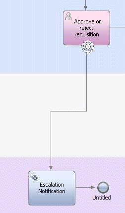
- You can complete the escalation path by building an underlying service to implement the Escalation Notification activity.
- You can attach more than one timer event to an activity. Using this example, you can attach another timer event to the activity that triggers two days after the due date has passed, thereby providing multiple notifications should the business user fail to perform the task after the first notification is received.
Related concepts:
Hiring Sample for Process Designer
Use intermediate timer events
Use intermediate timer events to cause a delay between activities.
If a timer event is not attached to an activity, it causes a delay. The process waits for the timer to trigger before proceeding to the next activity. For example, if your BPD includes an activity that emails offers to customers and you want your internal sales team to follow up two days after the offers are mailed, you can place a timer between the two activities. The delay ensures that a specific amount of time passes between the completion of one activity and the start of another.
In the case where the timer event is connected to an event gateway, the timer serves as a timeout. If the other events connected to the gateway do not trigger within the configured timeframe, the timer event triggers and the other events stop waiting.
You can set the properties for an intermediate timer event in the same way as outlined for the "Using attached timer events" procedure. The only difference is there are no Boundary Event Details options.
Modeling message events
Use a message event to represent a point in your process where an incoming message is received or where an outgoing message should be sent.
Incoming messages can originate from a message event in a process, from invoking an undercover agent in a service, from a web service that you create, or from a message that you post to the JMS Listener. To create web services to initiate inbound requests from external systems, see Publishing IBM Business Process Manager web services.
To create post a message to the JMS Listener, the Event Manager has a defined XML message structure that it must receive from an external system. See Posting a message to IBM Business Process Manager Event Manager for more information about the required message structure.
Outgoing messages can be received by a message event in a process, can be sent to call an external service, or can be received by the start event in another process or processes. To learn how to configure message events to send messages, see Use intermediate message events and message end events to send messages.
You can include the following types of message events in your BPDs:
| Event type | Implementation | When to use |
|---|---|---|
| Start event | Message configured to receive (Start events can only receive messages) | Use to model the start of a process if you want an incoming message event to kick off the process. A BPD can include more than one start message event.
Use as the start event for an event subprocess when you want the event subprocess to be triggered upon receipt of a message. |
| Intermediate event | Message configured to receive | Use to receive a message event. Intermediate events can be attached to activities within your BPDs or they can be included in the process flow, connected with sequence flows. |
| Intermediate event | Message configured to send | Use to send a message event. Intermediate events can be included in the process flow, connected with sequence flows. |
| End event | Message configured to send (End events can only send messages) | Use to send a message event at the end of a path. |
When you create a message event, you can cut and paste or copy and paste that message event within the same BPD or from one BPD into another BPD.
Before including any type of message event in a BPD, you should be aware of the following:
- Messages can be received by any running process that contains one or more message event.
- You can configure message events to consume messages. If you do, when a message is delivered to a running process, the message is consumed by the first message event in the BPD that can accept it (as determined by the undercover agent that is attached to the message event). When a message is consumed, it will not be processed again by that message event, or any other message event in the BPD instance that can accept it, should the execution of the BPD instance loop back and reach the same message event(s). If a new instance of the message is delivered to the process instance, this message is available for consumption again and is accepted by the message event.
- Message events can be used to enable roll-forward scenarios in which the same message needs to be passed through multiple steps until it reaches the appropriate step in the process where it is to be consumed. To enable rolling a message forward through multiple message events, enable the Consume Message option only for the last message event in the chain of roll-forward message events. You can also use conditions to further control message consumption.
- Occasionally, you may need to set conditions on the processing of incoming messages. If the condition specified evaluates to true, the message is accepted and processing continues-otherwise, it is stopped. Because the message condition is evaluated before the message values can be passed to the input variables of the process definition, the message values are passed to the condition in a special namespace, tw.message . If the message condition evaluates to true, the values are passed from the tw.message namespace to the BPD input variables.
- Use start message events For a process or event subprocess to start when a message is received, use a Start Message Event in your business BPD or inside your event subprocess.
- Use intermediate message events to receive messages You can include an intermediate message event in your BPD when you want to model a message event received during execution of a process.
- Use intermediate message events and message end events to send messages You can include an intermediate message event in your BPD when you want to model a message event that is sent during execution of a process, or a message end event when you want to send a message at an end of a path.
- Set the target for a message event While you are configuring a message event in a business BPD or configuring an Invoke UCA step in a service to use a message event, you can exercise some control over which snapshots use the event. You can override the default target by selecting a check box in the implementation settings for the undercover agent (UCA) that carries the event.
- Use message end events You can use a message end event when you want to send a message at an end of a path.
Related tasks:
Use start message events
For a process or event subprocess to start when a message is received, use a Start Message Event in your business BPD or inside your event subprocess.
For example, you may want an employee on-boarding process to start when a record for each new employee is created in your HR system. When the record is created, the system sends an event to IBM Business Process Manager. BPM captures the event and starts the follow-on steps for each new employee such as setting up the necessary space and computer equipment, requesting and creating a security badge, and so on.
When modeling start message events, you should be aware of the following:
- The general information that applies to all types of message events covered in Modeling message events .
- When a message is received by a start message event (specifying that an incoming message is to start a process at run time), a new instance of the process is created and a unique BPD instance ID is assigned to it.
- If you use multiple start message events in a single BPD, use a separate undercover agent for each. If using the same undercover agent for multiple start message events, BPM instantiates multiple instances of the BPD.
- In your BPD or event subprocess, drag a Start Event component from the palette onto the diagram.
- Click the Implementation option in the properties.
- Click the drop-down list and select Message from the Start Event types.
- In the Message Trigger section, click Select next to the Attached UCA field to select an existing undercover agent.
To create an undercover agent, click New. See Understanding and using undercover agents.
Ensure the sender and receiver of the message both use the same undercover agent. For example, if the sender of the message is a message end event in another BPD, then select the same undercover agent for both the receiving start event and the sending message end event in the other BPD.
- In the Condition text box, type a JavaScript expression to define conditions under which the message event is processed.
If you do specify a condition and the condition evaluates to true, the message is accepted and processing continues. If the condition evaluates to false, processing stops. In most cases, special message conditions are not necessary.
- Enable the Consume Message check box if you want the incoming message to be consumed after it has been received by the message event. Refer to the bulleted list in Modeling message events to learn more about message consumption.
- The Durable Subscription check box is not available for start message events, only for intermediate message events as described in the following section.
- Click the Data Mapping option in the properties.
- Map one or more of the listed undercover agent output variables to appropriate input variables when you want their runtime values passed to the BPD instance.
For example, if the start message event starts an instance of an on-boarding process when an employee record is created in your HR system, you can map the employee information from the undercover agent to a local variable in the BPD.
If your start message event is inside an event subprocess, you must select a variable to be used for correlating process instances. Correlation allows BPM to identify the process instance the message is meant for.
For example, an employee number might be used to uniquely identify a given instance of an on-boarding process. Selecting this variable for correlation ensures that when the data related to a given employee number is passed to the event subprocess, the appropriate instance of the on-boarding process is found.
Use intermediate message events to receive messages
You can include an intermediate message event in your BPD when you want to model a message event received during execution of a process.
Intermediate message events can be attached to activities within your BPDs or they can be included in the process flow, connected with sequence flows.
To build a sample inbound integration that includes an intermediate message event, see Building a sample inbound integration .
When including intermediate message events in a BPD, you should be aware of the following:
- The general information that applies to all types of message events covered in Modeling message events.
- You can enable durable subscriptions for intermediate message events. When a message arrives before a process has run to a point where the event can accept the message, the durable subscription causes the message to be stored until the message event is reached. Only the most recently received message is stored.
- When the process execution reaches an intermediate message event, further execution along that path is blocked until an incoming message arrives.
- When you use an attached or intermediate message event to receive messages, you must select an undercover agent output variable to assign a correlation value that will ensure the parameter values of the runtime message are passed to the correct BPD instance. You must also map the undercover agent output variables to local variables in the BPD.
- Drag an Intermediate Event component from the palette onto the BPD diagram so that it is attached to an activity.
The event is anchored to the activity. To verify this, select the activity. If the activity's outline includes the event, the event is attached.
For a sample of an intermediate message event that is included in the process flow, connected with sequence lines, see Building a sample inbound integration.
- Click the Implementation option in the properties.
- Click the drop-down list and select Message from the Intermediate Event types.
- In the Boundary Event Details section, the Interrupt Activity? check box is selected by default. This setting closes the attached activity when the message event is triggered. You want this behavior in cases where the receipt of the message event signals completion of the activity. Otherwise, clear this check box.
- In the Message Trigger section, click Select next to the Attached UCA field to select a preexisting
undercover agent.
To create an undercover agent, click New. See Understanding and using undercover agents.
UCAs must have a schedule type of On Event to function as a message trigger. Plus, the service attached to the selected undercover agent must have one or more input variables so that it can pass and correlate information from the event.
Ensure the sender and receiver of the message both use the same undercover agent. For example, if the sender of the message is a message end event in another BPD, then select the same undercover agent for both the receiving intermediate event and the sending message end event in the other BPD.
- In the Condition text box, type a JavaScript expression to define conditions under which the message event is processed.
If you do specify a condition and the condition evaluates to true, the message is accepted and processing continues. If the condition evaluates to false, processing stops. In most cases, special message conditions are not necessary because you should implement each message event with a separate undercover agent.
- Enable the Consume Message check box if you want the incoming message to be consumed after it has been received by the message event. Refer to the bulleted list in Modeling message events to learn more about message consumption.
- Select the Durable Subscription check box to allow the message event to receive an incoming message, even when the message event is not in an active state. (When a token is on a step, that step is in an active state. See Understanding tokens for more information.)
If you occasionally use inbound messages and undercover agents, consider using durable subscription events.
When Durable Subscription is selected, incoming messages are persisted in the database. The durable messages accumulate, even if you select the check box to make them consumable.
Periodically use the BPMDeleteDurableMessages
command for deleting durable subscription events.
- Click the Data Mapping option in the properties.
- In the Output section:
- Click the variable selector icon on the right side of each field to map each undercover agent output variable to a local variable in the BPD.
- Select the variable to use to correlate the event with the BPD instance. The variable selected for correlation is identified by an assignment symbol (
 ). This correlation ensures the parameter values of the runtime message are passed to the correct BPD instance. (IBM Business Process Manager only requires one variable mapping to correlate the event.)
For undercover agents that are implemented using a complex variable rather than a service, you can select the complex variable or the top-level child properties of the variable for mapping or correlation.
Related concepts:
Inbound events for the BPM document store
BPMProcessInstancesCleanup command
BPMDeleteDurableMessages command
Configure an undercover agent for a message event
Attaching the undercover agent to the message event
Use intermediate message events and message end events to send messages
You can include an intermediate message event in your BPD when you want to model a message event that is sent during execution of a process, or a message end event when you want to send a message at an end of a path.
For example, you may want to call an external service or to send a message to be received by the start event in another process or processes. Message events can be included in the process flow, connected with sequence lines. Intermediate message events have both incoming and outgoing sequence flows, while message end events have only incoming sequence flows. When including message events in a BPD, you should be aware of the general information that applies to all types of message events covered in Modeling message events.
- Drag an intermediate or end event from the palette onto the BPD diagram.
- In the text box that displays over the event, type a name for the event.
- Use the Sequence Flow tool to connect the event as needed.
- Select the event in the diagram and go to the Implementation tab of the Properties view. The default implementation for intermediate events that are included in the process flow is Message. If you are creating a message end event, select Message end event as the implementation type.
- If you are creating an intermediate message event, select Sending from the available message types in the drop-down list. By default, all message end events are sending message end events.
- In the Message Trigger section, click Select next to Attached UCA to select an existing undercover
agent, or click New to create one.
Ensure the sender and receiver of the message both use the same undercover agent. For example, if the receiver of the message is an intermediate message event in another BPD, then select the same undercover agent for both the sending message event and the receiving intermediate message event in the other BPD.
UCAs must have a schedule type of On Event to function as a message trigger. In addition, the service attached to the selected undercover agent must have one or more input variables so that it can pass and correlate information from the event.
- Go to the Data Mapping tab in the Properties view.
- In the Input section, click the variable selector icon on the right side of each field to map each undercover agent input variable to a local variable in the BPD. Click the Use default check box to use a default value from the attached undercover agent for a particular variable. When you enable this check box, the variable selector icon is disabled.
BPMProcessInstancesCleanup command
BPMDeleteDurableMessages command
Configure an undercover agent for a message event
Attaching the undercover agent to the message event
Set the target for a message event
While you are configuring a message event in a business BPD or configuring an Invoke UCA step in a service to use a message event, you can exercise some control over which snapshots use the event. You can override the default target by selecting a check box in the implementation settings for the undercover agent (UCA) that carries the event.
You can include an intermediate message event in your BPD when you want to model a message event that is sent or received while a process is running, or you can use a start event to receive a message event or use an end event to send a message event.
The default behavior for intermediate incoming message events is they are received by all snapshots in all process applications that refer to the undercover agent and that have event message properties that match the correlation values.
For start message events, the default behavior is they are used on the tip in Process Center and in the default snapshot on Process Server.
To change that default behavior, select the check box labeled Target the snapshot of the installed process application that contains this BPD or Target the snapshot of the installed process application that contains this service. (The label depends on your context.) You encounter the check box when you are configuring the undercover agent for a message event. If you select the check box, at run time start message events are targeted in the same snapshot of the process application that contains the BPD or the service that sends the message event. If the BPD or the service of the sending message event is in a toolkit, the snapshot of the process application (which is the root container) is used.
When the check box is selected, you are limiting the responding listener to the start message event and to the intermediate incoming message events in that specific process application snapshot.
Related tasks:
Attaching the undercover agent to the message event
Use intermediate message events and message end events to send messages
Configure an undercover agent for a message event
Use message end events
You can use a message end event when you want to send a message at an end of a path.
For example, you might want to send a message to be received by the Start event in another process or processes. When including message end events in a BPD, you should be aware of the general information that applies to all types of message events covered in Modeling message events.
- Open a BPD in and click the Diagram tab.
- Drag an end event from the palette onto the diagram.
- In the text box that appears over the event, type a name for the event.
- Click the Implementation option in the properties.
- Click the drop-down list and select Message from the end event types. By default, message end events can only send messages.
- In the Message Trigger section, click Select next to Attached UCA to select an existing undercover
agent.
To create an undercover agent, click New. See Understanding and using undercover agents.
Undercover agents must have a schedule type of On Event to function as a message trigger. Plus, the service attached to the selected undercover agent must have one or more input variables so that it can pass and correlate information from the event.
Ensure the sender and receiver of the message both use the same undercover agent. For example, if the receiver of the message is an message intermediate event in another BPD, then select the same undercover agent for both the sending message end event and the receiving intermediate event in the other BPD.
- Click the Data Mapping option in the properties.
- In the Input section, click the variable selector icon on the right side of each field to map each undercover agent output variable to a local variable in the BPD. Click the Use default check box to use a default value from the attached undercover agent for a particular variable. When you enable this check box, the variable selector icon is disabled.
Use ad hoc events
Use an ad hoc event when you need to include ad hoc actions that can be run at any time during process execution.
To enable end users to perform an ad hoc action during the execution of another process, you can do so by using a start ad hoc event in your BPD. For example, you may want to enable end users to cancel an order, determine the status of an order, or perform some other ad hoc function during the normal processing of an order. Because an ad hoc action is run in the context of the regular process instance, it has access to all the data of the regular process instance and can also manipulate the flow of the regular process instance, depending on the logic that you include.
Process Portal users who perform ad hoc actions must be assigned to the security group that is configured for the ACTION_INJECT_TOKEN policy. Modify the security properties of the BPMActionPolicy configuration object as described in Security configuration properties.
- Building a sample ad hoc action This example shows how to model an ad hoc action that enables users to view the contents of a requisition at any time during normal processing of the requisition.
- Testing a sample ad hoc action Use Process Designer to test the sample ad hoc action.
Related tasks:
Restrict access to actions on BPDs and tasks
Building a sample ad hoc action
This example shows how to model an ad hoc action that enables users to view the contents of a requisition at any time during normal processing of the requisition. For the following example, you can use the Standard HR Open New Position BPD included in the Hiring Sample process application. (If you do not see the Hiring Sample process application in your list of applications in the Process Center Console, ask your IBM Business Process Manager administrator to give you access.) To do so, clone a snapshot of the Hiring Sample process application so that your changes do not affect other users of Process Designer.
- Open the BPD in Process Designer and click the Diagram tab.
- Drag a swimlane from the palette to the diagram.
- Right-click the new lane and select Move Lane Down until the new lane is the last lane in the BPD (below the System lane).
- Click the new lane in the diagram (named Untitled 1 by default) and in the Name field in the properties, type Ad hoc event .
- Drag a start event from the palette onto the BPD diagram so that it is positioned in the new Ad hoc event lane.
- In the text box that displays over the start event , type Show Requisition Data for the event name.
- Click the Implementation tab in the Properties view and select Ad Hoc from the available start event types. If you wanted to restrict the users who can perform the action, you could also associate a specific team with the swimlane and then in the Event Visibility section specify the event visibility is restricted by swimlane.
- Drag an activity from the palette into the Ad hoc event lane.
- In the text box that displays over the user task,, type Show Data for the user task name.
- Drag an end event from the palette onto the BPD diagram so that it is positioned after the Show Data activity in the Ad hoc event lane and optionally name the end event.
- Use the Sequence Flow tool, connect the Show Requisition Data start event, the Show Data activity, and the end event on the BPD diagram.
- Right-click the Show Data activity and select Activity Wizard from the list of options.
- In the Activity Wizard - Setup Activity window, make the following selections:
Recommended selections in the Activity Wizard - Setup Activity window
>Option >Selection Activity Type User Task Service Selection Select the Create a New Service or Process option. In the Name field, type Show Data for the new service. (For this example, name the new Human service the same as the corresponding activity in the BPD.)
- In the Activity Wizard - Setup Activity window, click Next.
- In the Activity Wizard - Parameters window, choose the process variables from the regular process to use as input and output for the new service for the ad hoc process.
For the private variable named requisition, leave the Input field set to true and change the Output field to false. These settings reflect the fact that our sample ad hoc event simply displays the requisition data and does not pass back modified data. For other variables, click to change the setting from true to false under the Input and Output field. Click Finish.
The new service is created and attached to the activity. The new service includes a single Coach.
- Double-click the Show Data activity in the Ad hoc event lane in the BPD.
The new service opens and you can see the service diagram.
- Click the Coaches tab and then click the listed Coach to see its controls.
Because we used the Activity Wizard, the Coach includes a form element for each of the parameters in the requisition variable.
Save your work and then follow the instructions in Testing a sample ad hoc action.
Related concepts:
Hiring Sample for Process Designer
Testing a sample ad hoc action
Use Process Designer to test the sample ad hoc action.
Before you can test the sample ad hoc action, you must have a BPD that contains an ad hoc event and at least one task connected by sequence flow. For example, you can modify the Hiring Sample BPD to contain an ad hoc action as described in Building a sample ad hoc action.
- In Process Designer, open the BPD which contains the ad hoc action to test.
- Click the Run icon in the upper right corner of the BPD diagram.
- Process Designer switches
to the Inspector where you should see a new Submit requisition task in the task list.
- Open IBM Process Portal, and log in as a member of one of the participant groups who receive and can complete the tasks generated by the activities in the BPD.
- Run the Submit requisition task displayed in your Open Tasks view in IBM Process Portal.
- Fill out the Job Requisition information, click Next, and then Submit on the Confirm Job Position form.
- When the next task for the process instance (Approve/reject
requisition) displays in your Open Tasks view in IBM Process Portal, click the instance name or task subject to open the details page.
If the task does not display, reload the browser page.
- Click the Actions menu in the toolbar, and select the name of the ad hoc action. (The name of the action is the name that you assign the ad hoc event that initiates the user task in the BPD diagram in Process Designer.
If you are using the modified Hiring Sample, the name is Show Requisition Data. )
BPM generates a new task called Show Data, which is displayed in your Open Tasks view.
- Run the Show Data task. If you receive an information message about claiming the new task, click Claim Task. BPM displays the data that you entered in step 5.
- Click OK.
Now you can continue with normal processing by completing the next task in the process instance, Approve/reject requisition. You can invoke the ad hoc action again, after completion of the Approve/reject requisition task, to see whether the requisition has been approved.
The ad hoc event and user task that you added to the BPD diagram enables you to view the requisition information at any time during running of the regular process.
Related tasks:
Restrict access to actions on BPDs and tasks
Modeling event gateways
Use an event gateway to model a point in the process execution where only one of several paths can be followed, depending on events that occur. An event gateway represents a branching point in a process execution where only one of several paths can be followed, depending on events that occur. A specific event, such as the receipt of a message or timer event, determines the path that will be taken. The event gateway represents a single point of behavior that is spread out across multiple process components connected by sequence flow. The following types of events can directly follow an event gateway (connected by a single sequence flow):
- Intermediate message event (receiving)
- Intermediate content event (receiving)
- Intermediate timer event
When creating an event gateway, you must connect at least two intermediate events to the gateway. And, when connected to an event gateway, an intermediate event is not allowed to have additional incoming sequence flow.
- Drag a gateway from the palette to the process diagram.
- In the text box that displays over the gateway, type a name for the gateway.
- Click the General option in the properties.
- In the Behavior section of the general properties, click the drop-down list and select Event Gateway from the available gateway types. To streamline configuration of an event gateway, Process Designer automatically adds an intermediate message event (receiving) and an intermediate
timer event to the process diagram. These intermediate events are grouped with the event gateway in the process diagram.
- Add any additional events required by the gateway configuration by dragging them from the palette to the event gateway group in the process diagram. Only intermediate message events and intermediate timer events are allowed. The minimum number of events is two, and you can add as many as you require.
- Click an event in the group and then select the Implementation option in the properties.
- To configure an intermediate message event, follow the steps in Use intermediate message events to receive messages.
- To configure an intermediate content event, follow the steps in Performing modeling tasks for inbound events.
- To configure an intermediate timer event, follow the steps in Use intermediate timer events.
Handling errors using error events
When you design a business BPD or a service, provide logic to recover from possible errors that might be generated in the runtime application.
When you develop an application in BPM, build error handling into BPDs and services to detect errors, to specify how errors are thrown and caught in the runtime environment, and to recover in a predictable manner. For example, if a BPD involves filling orders, an item might be out of stock during one instance of the BPD, which causes an error. Error handling that you build into the BPD could create notifications to replenish items that are out of stock.
There are three types of error events: error end events in BPDs and services that throw errors, error intermediate events in BPDs and services that catch errors, and error start events in BPD event subprocesses that catch errors.
You can assign error codes and error data to errors that are thrown by the error end events.
To catch errors using error intermediate events, select an error code from a list of previously defined errors and map the error data to a variable. The error intermediate events are boundary events, which are intermediate events that are attached to the boundary of an activity. Each boundary event can be triggered only while the activity is running, interrupting the activity. From the BPD diagram or a service diagram in Process Designer, you can use an error intermediate event that is attached to the boundary of an active to catch specific errors and error data from a linked process, a subprocess, or a service.
Another way to catch errors is by using error intermediate events in services that catch all errors. When building services, you can attach an error intermediate event to the boundary of a step to catch all errors for the step, and you can use an error intermediate event as part of the service flow to catch all errors that are raised by steps of the service flow that are not handled by an error intermediate event at the boundary of the step.
You also can catch errors using error event subprocesses in BPDs. In the subprocess, you use an error start event that catches errors if the start event is triggered.
However you decide to catch errors, designate the error behavior for the events on the Properties tab in your diagram. Under Implementation, go to the Error Properties section to designate the following error handling behavior:
- Catch all errors or specific errors. To catch specific errors, you can select the error code, map the error data, or both, as described in the following bullets.
- Filter the specific errors that are caught by selecting an error code from a list of all thrown errors for the linked process, subprocess, or service.
- Map the error data into a variable by selecting an error mapping variable that was previously defined on the Variables tab.
If the error code has changed, make sure to select the variable again so that it is mapped properly.
If there are multiple error events defined to catch errors for an error that is thrown in a linked process, subprocess, or service, the catching event is determined by the precedence rules in the order they are listed in the Error event components table.
Errors are caught in the following order in the runtime environment:
- The boundary events catch errors that are raised by the attached activity, as described in the following table.
- If there is no error boundary event that handles the error, and a subprocess is in a BPD or in an unattached intermediate error event in a service, errors are caught in the error event subprocesses, as described in the following table.
- If there is no error event subprocess that handles the error in an event subprocess, linked process, or service, errors are propagated to the next level.
| Specify | Errors caught |
|---|---|
|
error code and error data |
Only errors with the same code and data type |
|
error code |
Errors with the same code, unless they are already caught by an event, as specified by the preceding rule |
|
error data |
Errors with the same data type, unless they are already caught by an event, as specified by the preceding rules |
|
neither code nor error data or the Catch All Errors option on error properties |
All errors not already caught by an event, as specified by the preceding rules |
Multiple events that are defined in the same context and with the same constraints cause nondeterministic runtime behavior.
Specifying the variable name in the mapping controls the filtering by error data type. If the type of the variable and the type of the error data that is displayed on the Properties tab do not match, the variable type determines the behavior.
- Handling errors in BPDs When modeling error handling as part of your business process definitions (BPDs), you can catch errors using error intermediate events or event subprocesses, and you can throw errors using error end events.
- Handling errors in services For services, you can use error intermediate events to catch errors, and you can use error end events to throw errors.
- Use error events in models from V7.5.x and earlier If you have Process Designer models from V7.5.x or earlier that use error events, the earlier error handling behavior is still available.
Handling errors in BPDs
When modeling error handling as part of your business process definitions (BPDs), you can catch errors using error intermediate events or event subprocesses, and you can throw errors using error end events.
| BPD event | Description |
|---|---|
error intermediate event  at the boundary
of an activity at the boundary
of an activity
|
|
error event subprocess that starts with an error start event 
|
|
error end event 
| Throws an error |
Catching errors using error intermediate events
For BPDs, you can attach an error intermediate event to an activity and connect that event to an error handling flow or activity.
To determine whether to use error immediate events, consider the following points:
- If an error occurs while a process is running an activity with an attached error event at the boundary, the process flows along the sequence line that is attached to the error event. Errors are handled in the flow and then proceed with the normal processing.
- Error intermediate events must be attached to an activity.
- You can have multiple error events for an activity, but only one catches the error.
- Consider specifying the error data to catch specific errors, filtering on the error code for the types of errors that are caught, and mapping to a variable after the errors are caught. When all errors are caught, or if only an error code is specified, the error data is captured in an XMLElement in the tw.system.step.error variable.
Catching errors using error event subprocesses
An event subprocess is a specialized type of subprocess that is not part of the normal sequence flow of its parent process. An error event subprocess is an event subprocess that contains an error start event. The event subprocess is not connected by sequence flow and runs only if the start event in the event subprocess is triggered. You can use error event subprocesses to handle errors in your BPD.
To determine whether to use error event subprocesses, consider the following points:
- Define a readable process by locating the error event in the event subprocess instead of defining it in the process.
- To reuse the error-handling flow for multiple tasks in your process, use event subprocesses. To reuse an error-handling flow using attached events, attach an intermediate event for each of the tasks and then connect those events to the error-handling flow.
- Define data objects that you can access only from within the event subprocess. You can define only those data objects that belong to a subprocess. The parent process is not cluttered with unnecessary variables.
For more information about event subprocesses, see Modeling event subprocesses.
Throwing errors
You can use an error end event in your BPD to specify an error code and map to an error type on errors thrown from the flow of a BPD or a service.
When working with either error events or event subprocesses, think about whether errors can be handled immediately, and normal processing can continue, or if another error can be thrown at another level. Then implement error handling from the bottom up. In other cases, it might be more efficient and readable if subprocess can be reused. Build each linked process and service so that errors can be captured and corrected. If a correction is not possible at the lowest level of the implementation, you can allow the error to move up a level by not including an error event or include an error event to rethrow the error to the calling service or process, as shown in the following section.
For example, to ensure that any errors that might occur during process run time are captured, you can create a high-level BPD that includes an activity to call the main process as a linked process and then one additional activity with an underlying service to implement error handling as shown in the following image:
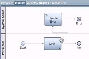
This type of design ensures that errors thrown from underlying processes and services are propagated up and handled appropriately.
Handling errors in services
For services, you can use error intermediate events to catch errors, and you can use error end events to throw errors.
| Service event | Description |
|---|---|
| error intermediate event attached to the boundary of a step
| Catches errors from the step |
| error intermediate event as part of the service flow
| Catches all errors raised by steps of the service flow that are not handled by an error intermediate event at the boundary of a step. This event can have only outbound links. |
| error end event
| Throws an error and ends the processing of this service. You might, for example, use an error end event when you want a particular result from a Coach to end a human service. |
To determine whether to use error events in your services, consider the following points:
- You must attach error intermediate events to steps in your service.
- Include error intermediate events in the service flow so they can act as global error handlers in the service.
- Determine whether errors can be handled immediately and normal processing can be continued, or if another error can be thrown at another level. Then implement error handling from the bottom up.
- Use an error end event to throw a specific error. You can specify an error code and error data for the error.
- Consider specifying the error data to catch specific errors. For example, you could filter on the error code for the types of errors that are caught and map the error code to a variable after the errors are caught. When all errors are caught, or if only an error code is specified, the error data is captured in an XMLElement in the tw.system.error variable.
Use error intermediate events in the service flow
The use of error intermediate events in a service flow offers several options in error handling, but it must be done carefully to prevent unexpected behaviour.
An error intermediate event in the service flow can act as a global error handler in the service. It catches errors not already handled by boundary error events. The error intermediate event cannot catch specific errors; it is a catchAll error event. It is meant for handling errors that can be handled within that very service flow. IBM recommends that you not wire back into the normal flow. Instead, after the error handling, logic should be concluded with an end event. After the error handling you might reenter the service and run the normal flow with corrected data.
To handle errors in a service and wire back to the normal flow in the same service, use one or more error boundary events with specific errors and the catchAll options.

An error intermediate event in the service flow also catches errors thrown through error end events of that service flow.
The error intermediate event can cause endless loops if follow-up activities after the event throw a runtime or a modeled error. The service engine prevents these loops. In some cases, it might be useful to model a loop with an intermediate error end event. To allow looping, add the following entry to 100Custom.xml:
<server>   <!-- insert if not already present -->
       <execution-context> <!-- insert if not already present -->
            <prevent-intermediate-error-loop  merge="replace">false</prevent-intermediate-error-loop>
        </execution-context> <!-- insert if not already present -->
</server> <!-- insert if not already present -->
Change this property will globally suppress the error loop detection of the service engine. Change this property only if all your models are free of endless error loops.
Use error events in models from V7.5.x and earlier
If you have Process Designer models from V7.5.x or earlier that use error events, the earlier error handling behavior is still available.
Models that were created in V7.5.x and earlier versions include the following error-handling behavior:
- Error intermediate events at the boundary of a step in services or at the boundary of an activity in a business BPD, subprocess, or event subprocess catch all errors. As of V8.0, you model this behavior using the Catch All Errors option, which is available on the Properties tab for a catching error event. In addition, you can refine your error handling by catching specific errors using the Catch Specific Errors option.
- Error intermediate events in the flow of a BPD, subprocess, or event subprocess were allowed but had no effect on runtime behavior. You can delete these events.
- Error end events in services, BPDs, subprocesses, or event subprocesses retain the same error throwing behavior: they can be caught only as part of an event that catches all errors. To use the extended error-handling capabilities, delete the old event and add a new event.
To use the latest error-handling capabilities, you can move the models to V8.0. Open your application, look at the referenced system toolkits, click a toolkit, and select the menu option to upgrade it.
Understanding and using undercover agents
An undercover agent is started by an event. The event can be a message event, a content event, or a timer event that is the result of a specific schedule.
Message events can originate from a Business Process Diagram (BPD) (see Modeling message events), from a web service that you create (see Publishing IBM Business Process Manager web services), or from a message that you post to the JMS listener (see Posting a message to IBM Business Process Manager Event Manager).
When an undercover agent executes, it invokes an IBM Business Process Manager service or a BPD in response to the event.
When you include a message event or content event in a BPD, attach an undercover agent to the event. For example, when a message event is received from an external system, an undercover agent is needed to trigger the message event in the BPD in response to the message.
To run the startBpdWithName application programming interface (API) to start a BPD instance inside an undercover agent, set the <enable-start-bpd-from-uca> property to true in 100Custom.xml or another override file. Restart the product, and check the TeamworksConfiguration.running.xml file to ensure the setting has the appropriate value. The property is set to false by default, and if you don't change it, you might have errors that prevent the BPD from starting.
- Configure an undercover agent for a message event Follow these steps to create an undercover agent that invokes a particular service as the result of an incoming or an outgoing message event.
- Configure an undercover agent for a scheduled event Follow these steps to create an undercover agent that invokes a service as the result of an event that occurs on a regular schedule.
- Configure an undercover agent for a content event To obtain information about document or folder events on an ECM server, create and configure a Content UCA that works with your event subscription. A Content UCA is used to initiate a BPM Start or Intermediate event when specific content changes occur on an ECM server. It is conceptually similar to a Message UCA, but it has a specialized Content marker to differentiate it from a Message marker.
Attaching the undercover agent to the message event
Configure an undercover agent for a message event
Follow these steps to create an undercover agent that invokes a particular service as the result of an incoming or an outgoing message event.
See Building a sample inbound integration to learn how to build a sample integration that includes this type of undercover agent.
- Start Process Designer and open the appropriate business BPD in the Designer view.
- In the Designer view, click the plus (+) sign next to Implementation and then select Undercover Agent from the list.
- In the New Undercover Agent window, enter the following information:
- Name: name for the new undercover agent.
- Schedule Type: Select On Event from the drop-down list.
- Click Finish.
- In the Common section, you can type a description of the undercover agent in the Documentation text box.
- In the Scheduler section, you can see the type of schedule for the current undercover agent in the Schedule Type field.
- Beside the Event Marker area, accept the default event marker Message. If you want, you can later click Select and then select Content. (The Content selection is used to work with content events that originate from ECM servers. By comparison, the Message selection is used to work with message events that originate from BPDs, JMS listeners, or web services that you have created.)
- Under Details, click the drop-down list next to Queue Name to select the queue that you want from the following options:
Available queue options
>Option >Description Async Queue Allows Event Manager jobs to run at the same time. SYNC_QUEUE_1 Forces one job to finish before the next job can start. By default, three synchronous queues are available. SYNC_QUEUE_2 Forces one job to finish before the next job can start. By default, three synchronous queues are available. SYNC_QUEUE_3 Forces one job to finish before the next job can start. By default, three synchronous queues are available. For more information about Event Manager jobs, monitoring those jobs, and creating and maintaining Event Manager execution queues, see Maintain and monitor IBM Business Process Manager Event Manager. When you install and run the process on a Process Server in a test or production environment, the queue that you select must exist in that environment in order for the undercover agent to run.
- Beside the Implementation area, accept the default selection Variable or select Service (if necessary). (Use a variable implementation to pass events directly from the UCA to the BPD. By comparison, use a service implementation to process information about events by adding business logic or decisions.)
- If you selected Variable, the default variable type NameValuePair is already selected. However, you can click Select to choose a different existing variable type or you can click New to create a new variable type.
- If you selected Service, the default attached service Default BPD Event is already selected. However, you can click Select to choose a different existing service or you can click New to create a new general system service.
- Ensure the Enabled check box is checked/enabled.
If this check box is not enabled, the Event Manager does not run the undercover agent when the message is received or sent. (The Event Manager monitor may show the Event Manager has run the undercover agent, but if this check box is not enabled, the execution does not occur.)
- In the Parameter Mapping section, click the Use Default check box to use the default value of the input variable in the attached service. If the input variable of the attached service does not have a default value, this check box is disabled.
Type a value in the text box to map a constant value to the input variable of the attached service. For example, you might use a constant for testing purposes.
In most cases, the required values are included in the incoming message event and no action is required here.
- In the Event section, BPM provides a default ID that is unique in the Event Message field.
This ID represents the event message for BPM processing.
If you are posting a message to BPM Event Manager from an external system, the ID in this field is the event name that you need to include in the XML message. See Posting a message to IBM Business Process Manager Event Manager for more information about the message structure.
If you are using a web service to enable an external application to call into BPM, you should not alter this ID. BPM seamlessly uses this ID if you create an inbound integration as described in Building a sample inbound integration.
- Open the BPD that includes the message event to which you want to attach the undercover agent. For example, if you want a particular process to start when a new customer record is created in an external system, you can associate the start event in the BPD with an undercover
agent that handles that incoming event.
Ensure the sender and receiver of a message both use the same undercover agent. For example, if the sender of a message is a message end event in another BPD, then select the same undercover agent for both the receiving start event and the sending message end event in the other BPD.
If you occasionally use inbound messages, consider using durable subscription events. Durable subscriptions are Java Message Service (JMS) subscriptions that persist and store subscribed messages even when the client is not connected. The durable messages accumulate, even if you select the check box to make them consumable.
Periodically use the BPMDeleteDurableMessages
command for deleting durable subscription events.
- Click the message event in the BPD to select it.
- Click the Implementation option in the properties.
- In the Message Trigger section, click Select next to Attached UCA and pick the undercover agent created in the previous steps.
- Click Save and switch back to the undercover agent editor.
- In the undercover agent editor, you can click Run Now to test the undercover agent and monitor it as described in Maintain and monitor IBM Business Process Manager Event Manager.
Use intermediate message events to receive messages
Use intermediate message events and message end events to send messages
Attaching the undercover agent to the message event
BPMDeleteDurableMessages command
Configure an undercover agent for a scheduled event
Follow these steps to create an undercover agent that invokes a service as the result of an event that occurs on a regular schedule.
Scheduled undercover agents do not run on the Process Center Server unless you click Run Now. If you are testing a BPD that includes scheduled undercover agents, and you want to ensure the undercover agents run on time, run the BPD on a Process Server in one of the runtime environments such as the development, staging or testing environment.
- Start Process Designer and open the appropriate process application in the Designer view.
- In the Designer view, select the plus (+) sign next to Implementation and then select Undercover Agent from the list.
- In the New Undercover Agent window, enter the following information:
- Name: name for the new undercover agent.
- Schedule Type: Select Time Elapsed from the drop-down list.
- Click Finish.
- In the Common section, you can type a description of the undercover agent in the Documentation text box.
- In the Scheduler section, you can see the type of schedule for the current undercover agent. After you have configured and saved the undercover agent, you can click Run Now to test the undercover agent and monitor it as described in Maintaining and monitoring IBM Business Process Manager Event Manager.
- Under Details, click the drop-down list next to Queue Name to select the queue that you want from the following options:
Available queue options
Option Description Async Queue Allows Event Manager jobs to run at the same time. SYNC_QUEUE_1 Forces one job to finish before the next job can start. By default, three synchronous queues are available. SYNC_QUEUE_2 Forces one job to finish before the next job can start. By default, three synchronous queues are available. SYNC_QUEUE_3 Forces one job to finish before the next job can start. By default, three synchronous queues are available. For more information about Event Manager jobs, monitoring those jobs, and creating and maintaining Event Manager execution queues, see Maintain and monitor IBM Business Process Manager Event Manager. When you install and run the process on a Process Server in a test or production environment, the queue that you select must exist in that environment in order for the undercover agent to run.
- Ensure the service shown as the Attached Service is the one to invoke according to the specified schedule. If not, click Select to choose a different service.
- Ensure the Enabled check box is checked/enabled.
If this check box is not enabled, the undercover agent will not run.
- In the Parameter Mapping section, click the Use Default check box to use the default value of the input variable in the attached service. If the input variable of the attached service does not have a default value, this check box is disabled.
Type a value in the text box to manually map a constant value to the input variable of the attached service. For example, you might use a constant for testing purposes.
- Scroll down to the Time Schedule section and use the available options to establish a schedule.
For example, to start the attached service every weekday at midnight, use the Ctrl key to select the options that are selected in the following image:
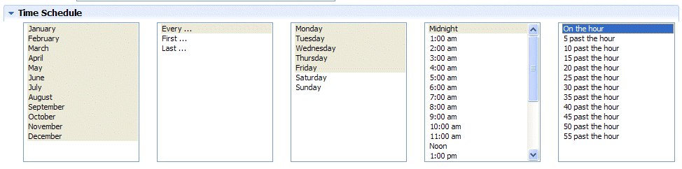
You can select multiple contiguous items by pressing the Shift key, clicking the first in the series, and then clicking the last in the series. To select multiple non-contiguous items, press the Ctrl key each time you click an item.
The On the hour value is selected by default in the last column of the Time Schedule section. If you clear this selection and you do not make any other selection in the column, the On the hour value will be used even though it is not selected.
If you select the First value and also select multiple weekdays, the undercover agent will run on the first occurrence of each selected day for the selected months. For example, if you select First and also select Monday, Tuesday, and Thursday, the undercover agent will run on the first Monday, Tuesday, and Thursday that occur in the selected months. Similarly, if you select the Last value and also select multiple weekdays, the undercover agent will run on the last occurrence of each selected day for the selected months. For example, if you select Last and also select Monday, Tuesday, and Thursday, the undercover agent will run on the last Monday, Tuesday, and Thursday that occur in the selected months.
- Open the BPD that includes the message event to which you want to attach the undercover agent. For example, if you want a particular process to start at the same time each day, you can associate the Start Message Event in the BPD with an undercover agent that establishes the required schedule.
- Click the message event in the BPD to select it.
- Click the Implementation option in the properties.
- In the Message Trigger section, click Select next to Attached UCA and select the undercover agent created in the previous steps.
Configure an undercover agent for a content event
To obtain information about document or folder events on an ECM server, create and configure a Content UCA that works with your event subscription. A Content UCA is used to initiate a BPM Start or Intermediate event when specific content changes occur on an ECM server. It is conceptually similar to a Message UCA, but it has a specialized Content marker to differentiate it from a Message marker.
This topic describes how to create Content UCA without consideration for some of the other components required to detect and respond to ECM events, such as an event subscription. To create a Content UCA and all of the other required components as well, you should follow the instructions in the topic Subscribing to document and folder events: the end-to-end approach. This is a simpler approach than creating each component on a stand-alone basis and it automatically creates some resources that you would otherwise need to create manually.
To create and configure a Content UCA...
- Create a Content UCA by completing the following steps:
- In the library area of the Designer page, click the plus (+) icon beside Implementation and then select Undercover Agent. The New Undercover Agent wizard opens.
- In the Name field, specify a name for the new UCA.
- In the Schedule Type drop-down list, select On Event.
- Click Finish. The UCA opens in the Undercover Agent editor.
- Configure the Content UCA by completing the following steps in the Undercover Agent editor:
- Beside the Event Marker area, click Select and then select Content. (Use the Content selection to work with content events that originate from ECM servers. By comparison, the Message selection is used to work with message events that originate from BPDs, JMS listeners, or web services that you have created.)
- Beside the Implementation area, accept the default selection Variable or select Service (if necessary). (Use a variable implementation to pass events directly from the UCA to the BPD. By comparison, use a service implementation to process information about events by adding business logic or decisions.)
- If you accepted Variable as your implementation, the default variable type ECMContentEvent is used and it cannot be changed.
- If you selected Service as your implementation, the default attached service Default ECM Event is already selected. However, you can click Select beside the Attached Service area and choose a different attached service for the UCA.
- Ensure the Enabled check box is selected, which enables the Content UCA to run.
- In the Parameter Mapping section, select the Use Default check box to use the default value of the input variable in the attached service. If the input variable of the attached service does not have a default value, this check box is disabled. You can type a value in the field to manually map a constant value to the input variable of the attached service. For example, you might use a constant for testing purposes.
- Click Save.
- If you accepted the Content event marker and you need to create an event subscription for the UCA, click Add Event Subscription and follow the instructions in the topic Configure event subscriptions.
- After you have configured and saved the Content UCA, you can click Run Now to test the Content UCA and monitor it as described in Maintain and monitor IBM Business Process Manager Event Manager.
The new configured Content UCA is displayed in the Undercover Agents section of the Implementation library list.
Work with BPM documents
In IBM Business Process Manager, you can use Enterprise Content Management (ECM) tools to work with BPM documents in the embedded BPM document store. For example, you can create, edit, and work with documents in the document store using either a Coach or a Heritage Coach. There are, however, special considerations for some of the CMIS operations that can be performed. The following topics provide additional information about working with BPM documents:
- The BPM document store The BPM document store is a CMIS-enabled embedded document repository used to store BPM documents in BPM version 8.5.0.0 or later. It supplants the document attachment feature that was used in earlier releases. The BPM document store supports CMIS operations and inbound events and use either Coaches or Heritage Coaches to work with BPM documents in the document store.
- Inbound events for the BPM document store The BPM document store supports a subset of the inbound content event types that are supported by external ECM systems. Event subscriptions for the BPM document store can only be created using the IBM_BPM_Document type.
- The IBM_BPM_Document document type In the BPM document store, BPM documents are represented by instances of the predefined document type IBM_BPM_Document.
- Create BPM documents You can create BPM documents by using a Coach View and by using content integration in a service.
- Update BPM documents You can update BPM documents by using a Coach View and by using the Content Integration node in a service.
- Work with the IBM_BPM_Document_Properties property Working with documents through the Content Integration node usually requires the manipulation of document properties.
- Work with BPM documents in the Document List Coach View The "Document List" Coach View can be configured to work with BPM documents. For BPM documents (and unlike Enterprise Content Management documents), the default search service included in the Content Management toolkit does not need to be overridden in the view configuration. The Document List will build a CMIS query that is based on the specified BPM document display options and then pass it to the service for execution.
- Limitations in working with BPM documents There are some limitations in working with BPM documents. In most situations, you can successfully work around these limitations.
Related tasks:
The BPM document store
The BPM document store is a CMIS-enabled embedded document repository used to store BPM documents in BPM version 8.5.0.0 or later. It supplants the document attachment feature that was used in earlier releases. The BPM document store supports CMIS operations and inbound events and use either Coaches or Heritage Coaches to work with BPM documents in the document store.
Related tasks:
Building a service that integrates with an ECM system or the BPM document store
Inbound events for the BPM document store
The BPM document store supports a subset of the inbound content event types that are supported by external ECM systems. Event subscriptions for the BPM document store can only be created using the IBM_BPM_Document type.
The inbound content event types that are supported for the BPM document store are listed in the following table:
| Inbound content event types | Description |
|---|---|
| Checked In | An event produced when a user checks in a document. |
| Checked Out | An event produced when a user checks out a document. |
| Check Out Canceled | An event produced when a user cancels the checkout of a document. |
| Created | An event produced when a user adds a document to the object store. |
| Deleted | An event produced when a user deletes a document. When a document is deleted, an event is fired for each item in the version series. For example, if a user deletes a document that has ten versions, ten events are fired. |
| Updated | An event produced on any action that updates
the property values or content of a document. Behavior will vary depending on the object and the action.
An Updated event is fired each time a new document is created. |
Related tasks:
Performing modeling tasks for inbound events
Use intermediate message events to receive messages
The IBM_BPM_Document document type
In the BPM document store, BPM documents are represented by instances of the predefined document type IBM_BPM_Document.
The properties for the document type IBM_BPM_Document are shown in the following table:
| Property | Type | Description | Value |
|---|---|---|---|
| IBM_BPM_Document_DocumentId | Integer | The numeric document identifier in BPM. | The identifier is automatically calculated and cannot be overwritten. |
| IBM_BPM_Document_ParentDocumentId | Integer | The numeric document identifier of the parent document in BPM. | The identifier is automatically calculated and cannot be overwritten. |
| IBM_BPM_Document_FileType | String | Indicates whether the document content contains "FILE" or references "URL". | Optional. If a value is not set, the value "FILE" is used. |
| IBM_BPM_Document_FileNameURL | String | The file name of the original document or URL. IBM recommends that this property is set. | Optional. |
| IBM_BPM_Document_HideInPortal | Boolean | Indicates whether the document should be hidden from Process Portal. | Optional. If a value is not set, the document is shown in Process Portal. |
| IBM_BPM_Document_ProcessInstanceId | Integer | The process instance identifier. If this property is set, the document is associated to the lifecycle of the process instance. The document content can only be viewed by those users who have authority to view the process instance. | Optional. If a value is not set, the document is associated to an instance (if the document creation is performed in the context of that process instance). The value can only be set on document creation. |
| IBM_BPM_Document_Properties | String[] | The additional properties of the document. The key and value should be separated by the comma (,) character. | Optional. |
| IBM_BPM_Document_UserId | Integer | The creator or last modifier of the document. | Optional. If a value is not set, the user ID of the caller is used. The caller can be the human service user (or the engine user when a human service is not used). |
Related tasks:
Work with the IBM_BPM_Document_Properties property
Create BPM documents
You can create BPM documents by using a Coach View and by using content integration in a service. You can use the following user interfaces to create BPM documents:
- The "Document List" Coach view (if it has been enabled to allow document creation). See the topic "Storing and viewing Enterprise Content Management documents."
- The Content Integration node that is available in the human service, Ajax service, and integration service editors. See the topic "Building a service that integrates with an ECM system."
If using the Content Integration node to create a document, you select the BPM document store as the target server and select the Create document operation. The only required value for this operation is the document name. The object type ID and folder ID are automatically specified because they are mandatory properties when the BPM document store is specified as the target server.
Optionally, you can also provide content and properties:
- To provide content, you can use an ECMContentStream variable. For an example of how to create a content stream, see "Working with document content."
- To provide properties, you can use a list of ECMProperty objects. All properties are optional and will default to a specific value if not specified. For more information about default values, see "The IBM_BPM_Document document type." Details and sample code to construct an ECMProperty list can be found in the topic "Working with the IBM_BPM_Document_Properties property."
Related concepts:
The IBM_BPM_Document document type
Related tasks:
Storing and viewing Enterprise Content Management documents
Building a service that integrates with an ECM system or the BPM document store
Work with the IBM_BPM_Document_Properties property
Related reference:
Update BPM documents
You can update BPM documents by using a Coach View and by using the Content Integration node in a service.
You can use the following user interfaces to update BPM documents:
- The Document List Coach view (if it has been enabled to allow document creation). See the topic "Storing and viewing Enterprise Content Management documents."
- The Content Integration node that is available in the human service, Ajax service, and integration service editors. See the topic "Building a service that integrates with an ECM system."
To use the Content Integration node to update documents, you must first check out the document. When the content or properties data is ready to be updated, the document must be checked in. Properties of an BPM document can be updated only through a check-in operation. The Update document properties operation, available for external Enterprise Content Management (ECM) servers, is not available for the BPM document store.
In a service flow, a typical update procedure might involve the following tasks:
- In the Content Integration node, specify the following options:
- Server: BPM document store
- Operation: Check-out document.
- In the Server Script node, populate the implementation with the code that is required to update the content or properties.
- In the Content Integration node, specify the following options:
- Server: BPM document store
- Operation: Check-in document. The document ID (private working copy ID) that is returned by the check-out document operation must be used as input to the check-in document operation.
For sample code and information on working with BPM document properties, see "Working with BPM document properties." For sample code and information on working with content streams, see "Working with document content."
Related concepts:
The IBM_BPM_Document document type
Related tasks:
Storing and viewing Enterprise Content Management documents
Building a service that integrates with an ECM system or the BPM document store
Work with the IBM_BPM_Document_Properties property
Related reference:
Work with the IBM_BPM_Document_Properties property
Work with documents through the Content Integration node usually requires the manipulation of document properties.
When you are working with BPM documents, you can use the document property IBM_BPM_Document_Properties to specify properties that are not defined in the document type IBM_BPM_Document. The IBM_BPM_Document_Properties property is defined as a string property that carries a name-value pair, each of which represents an extra property of the document.
Information about the document type IBM_BPM_Document and all of its available properties is found in the topic "The IBM_BPM_Document document type."
Information about working with the document property IBM_BPM_Document_Properties is found in the following topics:
- Writing to the IBM_BPM_Document_Properties property Properties can be written into a document when it is created or updated. In both cases, you can optionally provide the operation with a list of ECMProperty objects.
- Reading from the IBM_BPM_Document_Properties property The get document operation returns an ECMDocument object. This object contains the properties that are associated with the document.
- Update the IBM_BPM_Document_Properties property In an update scenario, only the properties that are passed into the check-in operation are updated in the document. BPM document properties are stored in the single CMIS property object IBM_BPM_Document_Properties. When a value is passed to the property object, the existing value for the property is overwritten. Be careful to ensure that when updating the property, only the intended updates are sent to the server.
- Specifying search criteria for the IBM_BPM_Document_Properties property After the "Document List" Coach View is configured to work with BPM documents, it automatically generates the CMIS query to pass to the search service. The query includes any required search conditions from the BPM document options specified for the view. However, if you intend to write your own CMIS query, or configure the Content Integration node for a search operation, then you must manually specify the format of the search condition.
Related concepts:
The IBM_BPM_Document document type
Related tasks:
Writing to the IBM_BPM_Document_Properties property
Properties can be written into a document when it is created or updated. In both cases, you can optionally provide the operation with a list of ECMProperty objects.
The following code shows an example of how to create the content of the IBM_BPM_Document_Properties property and store it into the list of ECMProperty objects that are passed into the document operation. The code below assumes to overwrite the existing value of the IBM_BPM_Document_Properties property.
  // Initialize the properties input variable to be passed to the Content Integration node    tw.local.properties = new tw.object.listOf.ECMProperty();

   // Initialize the  ECMMultiValue variable that will carry the name value pairs for the BPM properties    var props = new tw.object.ECMMultiValue();
   props.value = new tw.object.listOf.ANY();

   // Set the property name value pairs
   props.value[0] = "Property 1,value 1";
   props.value[1] = "Property 2,value 2";
   props.value[2] = "Property 3,value 3";

   // Create the IBM_BPM_Document_Properties property entry    tw.local.properties[0] = new tw.object.ECMProperty();
   tw.local.properties[0].objectTypeId = "IBM_BPM_Document_Properties";
   tw.local.properties[0].value = props.value;
For an example of how to update the value of the IBM_BPM_Document_Properties property, see "Updating the IBM_BPM_Document_Properties property."
Related tasks:
Update the IBM_BPM_Document_Properties property
Reading from the IBM_BPM_Document_Properties property
The get document operation returns an ECMDocument object. This object contains the properties that are associated with the document.
The following example code shows how to parse the value of the IBM_BPM_Document_Properties property into a variable that can be used in a service:
// Initialize the variable used to store the BPM property values. A list of NameValuePair objects is used.
tw.local.bpmProperties = new tw.object.listOf.NameValuePair();

// Look for the BPM properties object for (var i = 0; i < tw.local.document.properties.listLength; i++) {

   if(tw.local.document.properties[i].objectTypeId == "IBM_BPM_Document_Properties"){

        // Found the BPM properties.  Save its value to a local variable         var bpmProperties = tw.local.document.properties[i].value;

        // If there was only a single name-value pair stored in the BPM properties, then
        // a string is returned.  Need to check here.
       if(typeof bpmProperties == 'string'){

            // There is a string in the format "name,value". Store it into the output variable.
            var nameValuePair = bpmProperties.split(",");

            tw.local.bpmProperties[0] = new tw.object.NameValuePair();
            tw.local.bpmProperties[0].name = nameValuePair[0];
            tw.local.bpmProperties[0].value = nameValuePair[1];

        }else{
            // Else, there is an instance ECMMultiValue. Introspect this object and store everything into the             // NameValuePair list.
            for (var j = 0; j < bpmProperties.value.listLength; j++) {

                var nameValuePair = bpmProperties.value[j].split(",");

                tw.local.bpmProperties[j] = new tw.object.NameValuePair();
                tw.local.bpmProperties[j].name = nameValuePair[0];
                tw.local.bpmProperties[j].value = nameValuePair[1];
            }
        }
        break; // The BPM document properties object has been processed.  Exit the loop.
    }}
Update the IBM_BPM_Document_Properties property
In an update scenario, only the properties that are passed into the check-in operation are updated in the document. BPM document properties are stored in the single CMIS property object IBM_BPM_Document_Properties. When a value is passed to the property object, the existing value for the property is overwritten. Be careful to ensure that when updating the property, only the intended updates are sent to the server.
The following example code shows how to update the value of the IBM_BPM_Document_Properties property object:
// Find the ECMProperty object for the BPM document properties.  Assume the tw.local.document
// contains the document instance retrieved previously (by a get document operation, for example).
var bpmPropertiesEntry;
for (var j = 0; j < tw.local.document.properties.listLength; j++) {
   if(tw.local.document.properties[j].objectTypeId == "IBM_BPM_Document_Properties"){
        bpmPropertiesEntry = tw.local.document.properties[j];
        break;
    }}

// If there is a single BPM document property, the ECMProperty value will be a string.
// This is made an instance of ECMMultiValue, which enables the update to be // handled generically even if the number of properties eventually changes.
if(typeof bpmPropertiesEntry.value == 'string') {
    var value = bpmPropertiesEntry.value;
    bpmPropertiesEntry.value = new tw.object.ECMMultiValue();
    bpmPropertiesEntry.value.value = new tw.object.listOf.ANY();
    bpmPropertiesEntry.value.value[0] = value;
    }

// Cycle through the properties and update them with new values.
var bpmPropValues = bpmPropertiesEntry.value;
for (var j = 0; j < tw.local.bpmProperties.listLength; j++) {

    var updateValue = tw.local.bpmProperties[j];

    var found = false;
    for (var i = 0; i < bpmPropValues.value.length; i++) {

        var nameValuePair = bpmPropValues.value[i].split(",");

       if(updateValue.name == nameValuePair[0]){
            // Found the property, set the new value.
            bpmPropValues.value[i] = updateValue.name + "," + updateValue.value;
            found = true; // No need to add the property             break; // Property found, break out of the loop.
        }
    }

    // If the property is not found in the existing list, add it     // to the set.
   if(!found){
        bpmPropValues.value[bpmPropValues.value.length] = updateValue.name + "," + updateValue.value;
    }}

// Now the properties have been updated, populate the update operation with the input
tw.local.properties = new tw.object.listOf.ECMProperty();

tw.local.properties[0] = new tw.object.ECMProperty();
tw.local.properties[0].objectTypeId = "IBM_BPM_Document_Properties";
tw.local.properties[0].value = bpmPropValues.value;
Related tasks:
Writing to the IBM_BPM_Document_Properties property
Specifying search criteria for the IBM_BPM_Document_Properties property
After the "Document List" Coach View is configured to work with BPM documents, it automatically generates the CMIS query to pass to the search service. The query includes any required search conditions from the BPM document options specified for the view. However, if you intend to write your own CMIS query, or configure the Content Integration node for a search operation, then you must manually specify the format of the search condition.
Whether you provide your own CMIS search query, or build it using the Content Filter page in the service editor, the search predicate needs to follow a specific format.
To specify a search condition in the Content Filter page or to provide your own CMIS search query, complete the steps in the following procedure:
- To specify a search condition in the Content Filter page:
- In the Search Criteria section, select the Properties property.
- For the operator, select the contains property.
- Set the search value in the format BPM_property_name,search_value. For example, the search condition approved,true would find all BPM documents that have a BPM property name approved with a value of true.
Additional information about specifying search criteria is found in the topic "Building a query for an ECM search operation."
- In the Search Criteria section, select the Properties property.
- To provide your own CMIS search query, use the same format used for the search condition in the Content Filter page.
For example, the following search query will return the same results as the above search condition:
- ANY IBM_BPM_Document_Properties IN('approved,true')
Additional information about specifying a CMIS query is found in the "Query" section of the
OASIS Content Management Interoperability Standard (CMIS) specification.
Related tasks:
Building a query for an ECM search operation
Storing and viewing Enterprise Content Management documents
Work with BPM documents in the Document List Coach View
The "Document List" Coach View can be configured to work with BPM documents. For BPM documents (and unlike Enterprise Content Management documents), the default search service included in the Content Management toolkit does not need to be overridden in the view configuration. The Document List will build a CMIS query that is based on the specified BPM document display options and then pass it to the service for execution.
If you choose to provide your own search service and ignore the input CMIS query, the BPM document display options specified for the Document List will have no effect on the search result.
Your custom CMIS query must include the following document properties:
- cmis:name
- IBM_BPM_Document_FileNameURL
- IBM_BPM_Document_FileType
- cmis:objectId
- cmis:versionSeriesId
Optionally, you may also want to include the following properties to remain consistent with the default behavior:
- MajorVersionNumber
- cmis:lastModificationDate
- IBM_BPM_Document_UserId
The following example shows a sample CMIS query that includes all of these properties:
- SELECT cmis:name, IBM_BPM_Document_FileNameURL, MajorVersionNumber, cmis:lastModificationDate, IBM_BPM_Document_UserId, IBM_BPM_Document_FileType, cmis:objectId, cmis:versionSeriesId FROM IBM_BPM_Document
If the IBM_BPM_Document_UserId property is specified, the Document List displays the Last Modified By column. The column shows the full name of the user, which it obtains from the user ID value stored in the IBM_BPM_Document_UserId property. It is important to note that if you specify a query to filter for a specific user, you must provide the user ID (rather than the full name of the user) in the WHERE clause of the CMIS select statement.
Information about the Document List view is found in the topic "Stock content controls."
Related reference:
Limitations in working with BPM documents
There are some limitations in working with BPM documents. In most situations, you can successfully work around these limitations.
Some known limitations are:
- The BPM document store restricts document size to 1 gigabyte or less
- The BPM document store is not available on all platforms
These limitations are discussed in the following sections.
The BPM document store restricts document size to 1 gigabyte or less
If you attempt to create or enhance a BPM document and it results in a document size that exceeds 1 gigabyte, you will receive an error message that directs you to reduce the document size.
The BPM document store is not available on all platforms
Information about the platforms where the BPM document store is not available is found in the topic "Limitations in administering the BPM document store."
Related reference:
Use external implementations
You can create external implementations for activities that are handled by applications outside of IBM Business Process Manager. For example, you can model an activity that is run by a custom Eclipse RCP or Microsoft .NET application.
To use an external implementation to implement an activity in a business BPD, complete the tasks listed in this section.
In product releases older than V7.5.1, external implementations were referred to as external activities.
- Building a custom application to implement an activity Build a custom application using the BPM Web API to implement an activity in a BPD.
- Create an external implementation Create an external implementation in the Designer view when you want to reuse an existing external application or create an external application to handle one or more steps in your process.
- Use an external implementation to implement an activity Select a custom application to implement a particular activity (step) in a BPD.
Building a custom application to implement an activity
Build a custom application using the BPM Web API to implement an activity in a BPD.
To build a custom application to implement an activity within a process, use the BPM Web API to enable your custom application to interact with BPM. For example, the BPM Web API provides operations that enable you to pass variables from an BPM BPD to a custom application and then back to the BPD for continued processing.
Use the BPM Web API sample external implementation
IBM Business Process Manager includes a sample external implementation that illustrates how to use BPM Web API operations when developing a custom application to enable process participants to complete a particular step within a process. The Process Designer enables you to include these custom applications in your Business Process Definitions (BPDs) and model them as external implementations.
The Samples Exchange on Blueworks Live includes a sample external implementation. The sample external implementation is a custom Eclipse application that enables managers to either approve or reject expense reports from their employees. It represents one step in a process and can be modeled as an external implementation in Process Designer.
Download
the samples archive file from Sample Exchange Home. Search using keywords web-api.
If you import the BPD External Implementation Library and other associated components in the ExpenseApproval.twx file from the sample, the Eclipse application, combined with the corresponding library items, is a complete working example of external implementations.
Next topic: Create an external implementation
Developing using the web service API
Create an external implementation
Create an external implementation in the Designer view when you want to reuse an existing external application or create an external application to handle one or more steps in your process.
Use the external implementation function is similar to using the service functions like the integration service or web service. However, unlike those service functions that are designed for a specific area like web services or integration, the external implementation is more generic in nature. When a step in a business process is implemented with an external implementation, the business process halts and waits for input from the external application.
To create an external implementation, use the Web APIs or REST APIs.
The previous topic discusses a sample that creates an external implementation with the Web APIs. To create an external implementation with the REST
APIs, these articles are helpful. Use the REST APIs in BPM and  Integrating a business process application with an external system using the REST API. The related links at the bottom of this topic link to more information on the Web APIs and REST APIs.
When you create an external implementation in the Designer view in Process Designer, you need to know the properties to use to identify and run the custom application. If you did not build the custom application, you need to coordinate with the developers to ensure that you provide the appropriate properties in Process Designer.
- In the Designer view, click the plus sign next to Implementation and select External Implementation from the list of components.
- Supply a descriptive name for the new external implementation.
- Click Finish.
- In the Common section of External Implementation, optionally provide a description in the Documentation text box.
- In the Custom Properties section, specify the properties to identify and run the external application.
For example, for an external Eclipse RCP application, you might add custom properties to pass the Java Class name of the form to use for an activity or an application-specific identifier to look up the implementation by another means. Alternatively, you might use the external application name or system ID to find the implementation.
You can create parameters with a special meaning. For example, suppose you need to pass a URL address as a custom property? In the Custom Properties section you could use url as the name and then add a value that is the URL itself (http://mysite.com...).
You can also use this section to pass data to variables in a client that were instantiated with a constructor.
You can add custom properties to pass static metadata about the implementation to the external application. For dynamic data, which would be different for each process instance or environment, use the Parameter Details section as outlined in the following step.
- In the Parameters section, add the parameters for the external implementation by clicking Add Input or Add Output.
For example, if the external implementation provides an interface in which a manager can either approve or reject an expense report, it might include input parameters for the expense report data and output parameters for the decision the manager makes and the justification for his decision.
Be sure to account for all process data the external implementation requires to complete successfully and also for any data required from the external activity by subsequent activities.
- Click Save in the main toolbar.
Previous topic: Building a custom application to implement an activity
Next topic: Use an external implementation to implement an activity
Developing using the web service API
Developing client applications that use BPM REST APIs
Use an external implementation to implement an activity
Select a custom application to implement a particular activity (step) in a BPD.
The following steps describe how to select a custom application as the implementation for an activity in a BPD:
- Open a business BPD in the Designer.
- In the BPD diagram, click the activity to implement using a custom application.
- Click the Implementation tab in the properties.
- Under Implementation, select the User Task or System Task option from the displayed list.
- Click the Select button to choose an external implementation from the library.
If the external implementation has not been created, click the New button and follow the steps in Create an external implementation to create a new external implementation.
- In the Task Header section, specify the following properties:
Properties in the Task Header section
Property Action Subject Type a descriptive subject for the task that is generated in IBM Process Portal when you run the BPD. You can also use the BPM embedded JavaScript syntax ( <#=tw.local.mySubject#>) to express the subject. Narrative Type an optional description. You can also use the BPM embedded JavaScript syntax to express the narrative. Do not use JavaScript variable references in task narratives if you need the data to be available after the task completes. Once a task is complete, BPM removes the data for completed tasks to conserve space. Instead, store the data items in another location, such as a database.
For the following properties (in the Priority Settings section) you can click the JS button for an option if you prefer to use a JavaScript expression with predefined variables to establish the priority settings.
- For the Priority field, click the drop-down list to select one of the default priority codes: Very Urgent, Urgent, Normal, Low,
or Very Low.
- For the Due In field, you can enter a value in the text box and then choose Minutes, Hours, or Days from the drop-down list.
(When you choose Days, you can use the text box after the drop-down
list to include hours and minutes in your specification.)
You also have the option of using the variable selector next to the text box to choose an existing variable from the library. at run time, the variable should reflect the value that you want for the time period. Be sure to select the option that you want from the drop-down list: Minutes, Hours, or Days.
- For the Time Period field, click the drop-down list to select one of the options. For example, select 24x7 if you want 24 hours a day, seven days a week to be the time period in which the resulting tasks from the current activity can be due.
You can leave the Schedule, Timezone, and Holiday Schedule fields set to (use default). If you do, the work schedule specified for the BPD is used. See Set the due date and work schedule for a BPD for more information.
- For the Time Zone field, click the drop-down list to select the time zone to apply to the tasks that result from the current activity. For example, you can select US/Pacific for users who work in California.
- For the Holiday Schedule field, you can leave the setting at (use default) as described in the preceding note or you can click the JS button if you prefer to use a JavaScript expression.
Each Holiday Schedule is made up of a list of Dates.
If you choose JavaScript, you can enter either a String (or String-generated JavaScript) or JavaScript that returns a TWHolidaySchedule variable. If you use a String, then BPM looks up the holiday schedule by name according to those rules. If you use a TWHolidaySchedule variable, then BPM assumes the holiday schedule is filled in appropriately. (Go to the System Data toolkit and open the TWHolidaySchedule variable to view its parameters.)
- Click the Data Mapping tab in the properties.
Because you added the input and output parameters for the external implementation when you created it, the Data Mapping tab for the activity in the BPD should include those parameters.
Under Input Mapping, click the auto-map icon in the upper-right corner, and then click the auto-map icon in the upper-right corner of the Output Mapping section. For more information about mapping variables, see Business objects and variables.
Save the implementation.
Previous topic: Create an external implementation
Integrating with IBM Case Manager
To integrate with IBM Case Manager, you build an integration service and perform other key steps when you want to integrate a business process developed in Process Designer with a case management case in IBM Case Manager.
Business process management and case management are complementary ways of solving business problems. In business process management a sequence of activities in a business process leads to a result. Frequently, those activities are automated. For example, a business process might get traffic accident statistics in one activity and use business analytics in another activity to produce some possible causes for a rise in traffic fatalities.
In case management a specific case is looked at by a set of professionals related to it. A case could consist of a specific traffic accident and could have someone representing an insurance company, another looking at the legal aspects, and another examining safety equipment.
Together business process management and case management can effectively analyze problems by bringing the data together in a common domain.
An IBM Case Manager Integration service is the means of accessing case management cases from a business process. Accessing case management cases from an IBM Case Manager Integration service includes both searching for case management data and updating data.
The integration service you develop in this section is from BPM to IBM Case Manager.
To see the integration from IBM Case Manager to IBM Business Process Manager read Integrating with BPM.
- Add an Case Manager server You require at least one Case Manager server to build an IBM Case Manager Integration service.
- Building the IBM Case Manager Integration service Like other integration services, this service integrates with another system. Specifically, this service integrates a business process developed in Process Designer with an IBM Case Manager case management solution.
- Building a query for a search case operation A graphical interface helps you build a query to your IBM Case Manager solution.
- Processing a search case operation result A search case operation result is often used with an update case operation. Since an array is returned in a search case result, you would use JavaScript to iterate through each element of the array and perform multiple updates.
- Data mapping in case operations Each case operation requires that variables, or values in the case of input, be mapped to the input and output fields. Using the auto-map function creates variables, if required, and assigns variables of the right type to each field.
- Access an Case Manager server using SSL Some Case Manager servers may use SSL for security protection.
Add an Case Manager server
You require at least one Case Manager server to build an IBM Case Manager Integration service. To add a server, follow these steps.
- Select the Servers tab from the Process App Settings editor. You will see the Process App Settings editor when you first click Open in Designer from a newly created process application in the Process Center. Alternately you can select Process App Settings from the drop-down list on the toolbar in Process Designer.
- Beneath the Servers heading click Add. Beneath the Server Details heading, enter a meaningful name for server. From the drop-down list in the Type field, select IBM Case Manager Server. Enter a description of what the server does or provides in the Description field.
- Beneath the Server Locations heading,
enter the following information.
- Environment Type: The environment of the Case Manager server.
Enter the server location information (hostname, port, if it will be a secure service, target object store, connection userid and password)
for each environment type. If you do not provide values for these environments, the values from the default environment type will be used.
- Default: A set of default values that are used if you do not provide values for the following environment types.
- Development: The environment where you develop your services.
- Test: The environment where you test your services.
- Staging: The environment where you deploy your services for pre-production testing.
- Production: The environment where your services are deployed for use by your organization.
- Hostname: The hostname of the Case Manager server.
Specify an IP address or a hostname and domain (but do not specify http:// or another protocol). For example:
myHost.labwide.ibm.com
- Port: The port number of the Case Manager server.
- Secure: Select if you want your service to be secure, that is, use the Hypertext Transfer Protocol Secure (HTTPS) protocol. If you are accessing a server using SSL security, see Access an Case Manager server using SSL.
- Target Object Store: The target object store name for the Case Manager server. A target object store is used to store runtime case solutions. If you do not know the name, you should be able to get it from the Case Manager server administrator.
- Connection Userid: The userid for connecting to the Case Manager server.
- Password: The password of the userid connecting to the Case Manager server.
Save your work. From the menu, select File > Save All.
- Environment Type: The environment of the Case Manager server.
Enter the server location information (hostname, port, if it will be a secure service, target object store, connection userid and password)
for each environment type. If you do not provide values for these environments, the values from the default environment type will be used.
Building the IBM Case Manager Integration service
Like other integration services, this service integrates with another system. Specifically, this service integrates a business process developed in Process Designer with an IBM Case Manager case management solution.
The name for the IBM Case Manager solution use and the process application that you are currently using to develop your IBM Case Manager Integration service must be identical. Before developing your service, check that your IBM Case Manager solution name and your process application name match.
Should you rename the IBM Case Manager solution in future you will also need to rename the corresponding process application, and vice-versa. To build an IBM Case Manager Integration service, follow these steps:
- Click Implementation in the library section and select IBM Case Manager Integration Service from the menu to create a service the business process could use later. The library section is found in the upper
left area of Process Designer.
Enter a name for the service on the following dialog box and click Finish.
The IBM Case Manager Integration Service editor opens with the Diagram tab in focus.
- From the palette, drag an IBM Case Manager Integration step onto the canvas. The initial IBM Case Manager Integration step is named Untitled which you can rename to something more appropriate.
- Click Implementation in the Properties view. Under IBM Case Manager Server, select a case management server from the list of known servers. The drop-down list of servers is located in the Server field. These servers are initially defined under Process App Settings (see Add an Case Manager server). Should there be no entries in the list that means that no servers have been specified. Click Use Process Application Settings to add a server and add a server.
- Under Case Operation, select the appropriate operation.
- Create case: This operation lets you create a new case. A case is an instance of a case type.
- Search case: This operation retrieves a set of case references according to a query. See Building a query for a search case operation. The case references are returned in an array object.
- Retrieve case: This operation retrieves
a case, that is, a case instance, based on a case reference. It can be used with a search case operation which provides the case references.
- Update case: This operation lets you modify a case. See Processing a search case operation result to search for cases and then perform multiple updates by iterating through the array object that is returned.
- Beneath Case Type, select the type of case to use. For example, a case type for a case pertaining to insurance claims might have an Auto Claim case type.
Should your case type change in the future repeat the previous steps for the new case type name and regenerate the business objects which you do in the next step. In other words, changing a case type name in an IBM Case Manager solution is independent of creating this service.
- Click Generate Types. This generation creates the business objects which are used by variables to contain the data transferred between your service and the case management server. To see the business objects, click Data.
Note that generating the business objects does not mean that you have created variables with these business objects as types. You still need to create those variables to handle the input and output data for each operation. In the next step on data mapping, you can create these variables quickly by using an auto-map function.
- Click Data Mapping. This section lets you create the map between the variables for input and output.
As stated previously, these variables need to be created. A simple way to both create and map the input and output variables for an operation is to use the auto-map function. The auto-map function creates private variables for the business objects, which are used by the IBM Case Manager Integration service. Click the auto-map icon to create these private variables.

The mapping structure for each operation is discussed in Data mapping in case operations.
Save your work to update the process application with any changes to your service.
Building a query for a search case operation
A graphical interface helps you build a query to your IBM Case Manager solution. Follow these steps to add a query that can be used in a search case operation.
- In the IBM Case Manager editor, click the Case Filters tab.
- In the left column, select the search node you want to create your query for, if you created more than one search service.
- Beneath Build Case Filter complete the fields appropriate to your query.
- Use Mapping Variable (String): Select this check box only if you are experienced in writing Content Management Interoperability Services (CMIS) queries and want to write your own hand-coded query (see the query section of the CMIS specification for information on the syntax). You can improve your response time by qualifying your SELECT clause as follows: SELECT CmAcmCaseIdentifier,
cmis:objectId FROM ...
The case type in your query takes precedence over the case type specified in your service. If there is a difference between the case type in your query and the case type in your service, the case type in your query will be used.
Selection will disable the fields in case filter and make the Input Mapping field editable. Select the Data Mapping tab in the Properties view to see the Input Mapping field.
- Match criteria: Lets you select all or any as a match criteria. All returns cases matching all the criteria specified in the case filter. Any returns cases matching any single field in the case filter.
- Case ID: Lets you specify a case.
- Case State: Lets you specify the state of a case: working, complete or failed.
- Date added between: Lets you specify a period of time when a case was added to the case management solution.
- Added by: Lets you specify a userid that added a case.
- Date modified between: Lets you specify a period of time when a case was modified.
- Modified by: Lets you specify a userid
that modified a case.
- User-specified properties: Lets you specify custom properties found in the case type selected for the node.
Save your work. File > Save All.
- Use Mapping Variable (String): Select this check box only if you are experienced in writing Content Management Interoperability Services (CMIS) queries and want to write your own hand-coded query (see the
Processing a search case operation result
A search case operation result is often used with an update case operation. Since an array is returned in a search case result, you would use JavaScript to iterate through each element of the array and perform multiple updates. Follow these steps to make multiple updates using a search case result.
Although this topic is about a search case, it could also be applied to a retrieve case. For example, you could search for a case and for each case reference returned perform a retrieve to get the properties of each case instance. You could look upon this example as a pattern that can be used any time multiple case references need to be processed.
- In the IBM Case Manager Integration Service editor, create a flow of operations similar to the following screen capture.
- In the Loop Case References component, add JavaScript similar to the following in the Implementation section of the Properties view. It will let the loop run until there are no more cases in the array to process.
/* Assumes the counter variable will always be reset to -1 at the end of the loop */ tw.local.counter ++; /* Increase the counter by one */ tw.local.currentReference = null; /* Reset the current reference */ /* If the counter is within the length of the array, get the next case reference */ if(tw.local.counter <= tw.local.references.listLength){ tw.local.currentReference = tw.local.references[tw.local.counter];}else{ /* Else, reset the counter. The Reference is already null so the decision node should continue */ tw.local.counter = -1; } - In the Implementation section of the Properties view for the Decision Gateway, return the flow to the Update Case service when the currentReference variable from the JavaScript shown previously is not equal to a null value.
- Create a query to run against your IBM Case Manager solution as shown in Building a query for a search case operation.
- Run the business process that invokes this service.
A different situation to the one described in the previous steps is if you update a case instance in IBM Process Center that originated on the Case Manager server. When you return that case instance to the Case Manager server, use the tw.system.enclosingCaseInstance system variable as the reference to the case instance running on the Case Manager server. This variable is only available at the business process definition level.
Data mapping in case operations
Each case operation requires that variables, or values in the case of input, be mapped to the input and output fields. Using the auto-map function creates variables, if required, and assigns variables of the right type to each field.
This section shows you the mapping between the input and output fields.
- Input and output map for a create case operation
- Input and output map for a search case operation
- Input and output map for a retrieve case operation
- Input and output map for an update case operation
Input and output map for a create case operation
Input map:
- Case properties: An array of key-value pairs to initialize the properties of the case. The types are generated by the Generate Types button when you build your service. The properties have an integer, float, boolean, string or datetime type. The cardinality (number of elements) of the properties is either a single element or multiple elements.
Output map:
- Case reference: A reference to the IBM Case Manager case. It maps to the CaseReference business object found in the System Data toolkit.
- Return code: A return code indicating if the operation was successful.
- Response message: A response message from the server.
Input and output map for a search case operation
Input map:
- CMIS query: A string of text containing the Content Management Interoperability Services (CMIS) query.
Output map:
- Case references: An array of IBM Case Manager CaseReference objects that match the query. They map to the CaseReference business object found in the System Data toolkit.
- Return code: A return code indicating if the operation was successful.
- Response message: A response message from the server.
Input and output map for a retrieve case operation
Input map:
Case reference: A reference to an IBM Case Manager case. It maps to the CaseReference business object found in the System Data toolkit.
Output map:
- Case instance: An instance of the case type. The types are generated by the Generate Types button when you build your service.
- Return code: A return code indicating if the operation was successful.
- Response message: A response message from the server.
Input and output map for an update case operation
Input map:
- Case reference: A reference to an IBM Case Manager case. It maps to the CaseReference business object found in the System Data toolkit.
- Case properties: An array of key-value pairs to initialize the properties of the case. The types are generated by the Generate Types button when you build your service. The properties have an integer, float, boolean, string or datetime type. The cardinality (number of elements) of the properties is either a single element or multiple elements.
Output map:
- Return code: A return code indicating if the operation was successful.
- Response message: A response message from the server.
Access an Case Manager server using SSL
Some Case Manager servers may use SSL for security protection. These steps show you how to set up a connection to an Case Manager server using SSL.
- Launch the Administrative console and log in to the IBM Integration Solutions Console of the server running your IBM Process Center.
- For stand-alone servers, navigate to Security > SSL certificate and key management > Key stores and certificates > NodeDefaultTrustStore > Signer certificates. In a Network Deployment (ND) environment, the truststore is called CellDefaultTrustStore.
- Click Retrieve from port.
- In the Host field, enter the hostname, in the Port field enter the secure port number and in the Alias field enter an alias name for the Case Manager server you want to connect to.
- Click Retrieve signer information. Verify the retrieved information is the expected signer certificate of your Case Manager server. Click Ok if the retrieval is successful.
- In a Network Deployment (ND) environment, make certain all nodes are synchronized. Save your work and log out of the IBM Solutions Console.
- When you add this secure server in your process app settings page, use the host name and port used in the IBM Solutions Console. Click the Secure check box.
Integrating with Enterprise Content Management (ECM) systems
You can interact with an ECM server to store or view documents.
ECM systems manage documents of different types such as records, images, and web pages throughout their lifecycle. ECM systems are used to increase efficiency and to monitor the security of information, and comply with industry and government regulations. You can access and update these documents from a business process by using Enterprise Content Management operations in services such as an integration service or human service.
For Enterprise Content Management integration, there are predefined types and services that you can use. These types and services are contained in the Content Management (SYSCM) toolkit.
- Add an ECM server You need at least one Enterprise Content Management (ECM) server for the service you develop. You specify the connection properties to access an ECM server on the Process App Settings Servers page for a process application or on the Toolkit Settings Servers page for a toolkit. Adding the server to the Toolkit Settings Servers page allows the connection properties to be reused.
- Outbound interactions with Enterprise Content Management systems You can implement queries and services that interact with Enterprise Content Management servers.
- Inbound events from Enterprise Content Management systems In IBM Business Process Manager, you can create event subscriptions and design business processes and services that detect and respond to inbound content events from Enterprise Content Management (ECM) systems. The content events are used to catch and throw interactions with an ECM system. Business processes can instantiate, continue, or end based on the type of content event, such as the creation, modification, or deletion of a document.
- Troubleshooting interactions with Enterprise Content Management systems From time to time, you may encounter some issues during interactions with Enterprise Content Management (ECM) systems. In most situations, you can successfully work around these issues.
- Integration considerations for ECM products To work with specific ECM products, it is helpful to have an understanding of their main integration considerations, such as their CMIS capabilities and limitations.
Add an ECM server
You need at least one Enterprise Content Management (ECM) server for the service you develop. You specify the connection properties to access an ECM server on the Process App Settings Servers page for a process application or on the Toolkit Settings Servers page for a toolkit. Adding the server to the Toolkit Settings Servers page allows the connection properties to be reused. To add a server, follow these steps.
- Select the Servers tab from the Process App Settings editor. You see the Process App Settings editor when you first click Open in Designer from a newly created process application in the Process Center. Alternatively you can select Process App Settings from the drop-down list on the toolbar in Process Designer.
- Beneath the Servers heading click Add. Beneath the Server Details heading, enter a meaningful name for server. From the drop-down list in the Type field, select Enterprise Content Management Server. Enter a meaningful description of the server in the Description field. This field is optional.
- Beneath the Server Locations heading,
enter the following information.
- Environment Type: The environment of the ECM server. Enter the server location information (host name, port, context path, whether it is a secure server, repository name, user ID, and password) for each environment type. These environments are described in the product
overview. Modify
the Process Server environment shows you how to change these types. If you do not provide values for these environments, the values from the default environment type are used.
- Default: If you do not provide values for the following environment types, default values are used.
- Development: The environment where you develop your services.
- Test: The environment where you test your services.
- Staging: The environment where you deploy your services for pre-production testing.
- Production: The environment where your services are deployed for use by your organization.
- Hostname: The host name of the ECM server. Specify an IP address or a host name and domain. For example:
myHost.labwide.ibm.com
- Port: The port number of the ECM server.
- Context Path: The path to the Content Management Interoperability Services (CMIS) web services application on the server. A connection must be established through Content Management Interoperability Services (CMIS) using the web services protocol rather than the Atom protocol.
- Secure server: Specify whether you want your service to be secure, that is, to use the HTTPS protocol by selecting this check box. If you select the HTTPS protocol, configure HTTPS security, as described in Access an Case Manager server using SSL.
- Repository: The name of your repository.
- Userid: The user ID to connect to the ECM server.
- Password: The password of the user ID connecting to the ECM server.
- Always use this connection information:
If selected, which is the default, only this user ID and password are used for authentication.
For example, a human service, which your service is associated with when a Document List or Document Viewer is configured, also has a user context. An administrator uses the Manage Users function to specify human service users. Selecting this check box means this user ID and password overrides any other user information.
- Environment Type: The environment of the ECM server. Enter the server location information (host name, port, context path, whether it is a secure server, repository name, user ID, and password) for each environment type. These environments are described in the product
overview. Modify
the Process Server environment shows you how to change these types. If you do not provide values for these environments, the values from the default environment type are used.
- Click Test Connection to confirm the connection to the server works.
Save your work. From the menu, select File > Save All.
You can change these settings at run time. See Change Enterprise Content Management server settings.
Related concepts:
Use the event handler for FileNet Content Manager
Related tasks:
Create an event handler for an ECM system
Building a service that integrates with an ECM system or the BPM document store
Outbound interactions with Enterprise Content Management systems
You can implement queries and services that interact with Enterprise Content Management servers.
- Authentication scenarios IBM Business Process Manager provides three ways that you can grant access to an ECM server. You can set a user ID and password for the process application that is recognized by the ECM system. You can design a business process to use personal credentials to control access to specific documents and folders on the ECM server. Or, you can design a business process that uses each method of authentication for different steps in the process.
- How to use Coach views to store or view documents You can store or view documents from an ECM server by using functions that work with your search results.
- Building a service that integrates with an ECM system or the BPM document store Use a service to allow a business process developed in Process Designer to work with an ECM system or the BPM document store.
- Building a query for an ECM search operation A graphical interface helps you build a query to an ECM server.
- Work with a search result programmatically Search results can be substantial. Instead of working with a large search result in a user interface, you may want to parse the search results programmatically.
- Work with document content To work with the content of documents, you can use the ECMContentStream data type to wrap a content stream and return information about the stream. A content stream is a stream of data that contains the content of a document, such as a word processing document or an image.
- Data mapping in Enterprise Content Management operations Each operation requires that variables be mapped to the input and output fields. Using the auto-map function automatically creates and assigns variables of the right type to each field.
Authentication scenarios
IBM Business Process Manager provides three ways that you can grant access to an ECM server. You can set a user ID and password for the process application that is recognized by the ECM system. You can design a business process to use personal credentials to control access to specific documents and folders on the ECM server. Or, you can design a business process that uses each method of authentication for different steps in the process.
The IBM Business Process Manager system and the ECM system are separate systems. If shared security is not configured, the BPM system does not recognize Enterprise Content Management users and vice versa. Being authenticated on one system does not mean that a user or user group is also authenticated on the other system. Consider the way you want to share Enterprise Content Management information with BPM users before you design your application.
In some scenarios, you want to project the user identity of the currently acting human user from the BPM system to the ECM system. This approach allows users to create and access private documents, provides records for audits, and allows fine-grained access control on the ECM server. In other scenarios, the actual user identity of the human user who is working with BPM does not matter in the ECM system. In such cases, it might be enough to use a static system identity that represents the BPM system. For example, the business process might generate public documents or perhaps all BPM users need to see the same collection of documents in a user interface.
When you configure access to an ECM server in Process Designer, you set a user ID and password (see the related links for more information about this task). If using the default setting, the ID and password do not need to be valid on the BPM system, but they must be valid for the ECM server. At the end of the settings is a check box labeled...
- Always use connection information specified here
When that check box is selected, which it is by default, that user ID and password are attached to all calls made from that process application to the ECM server. The advantage of this method is the ECM server is immediately available for use by the actions in the process application. However, do not use this option to restrict which documents or folders individual users can see and use. Using this method, a static user name and password as defined in the process application settings is the only credential that can be submitted from BPM to the ECM server. There is no way of telling the ECM system who the current "real" user is. Therefore, even if you set up single sign-on, there is no way of fine-grained access control and gathering auditing data by individual user.
Clear the "Always use connection information specified here" check box to restrict which documents or folders individual users or specific user groups can see and use. When that check box is not selected, the BPM system uses individual user names and IDs for authentication and projects the identity to the ECM server. Now you can assign specific tasks to users who can see only the documents and folders they need to complete those tasks. A service that is started by a user task in a BPD runs under the security context of the user who claimed and started the task.
You can design a business process definition to use both authentication methods, depending on the context. If the "Always use connection information specified here" check box is not selected, authorization depends on how you model your business process. By choosing the context from which the call is made, you can restrict access to the ECM server to a user ID specified in the process application server settings or to a task owner. If the ECM service is called by a system task in a BPD, the user identified in the process application settings is used. If the ECM service is called by a human task, by a coach, or by an integration service within a user task, the task owner identity is propagated to the ECM system. In this latter case, the user ID and password set on the process application are ignored. Calls that use the task owner identity fail if the BPM and ECM systems do not have shared security.
Related concepts:
Manage IBM Business Process Manager configuration settings
Related tasks:
Change Process Server properties in 100Custom.xml
Change Enterprise Content Manager server settings
How to use Coach views to store or view documents
You can store or view documents from an ECM server by using functions that work with your search results.
To store a document at an ECM server you use a Coach view called Document List. Document List can retrieve a set of documents from an ECM server, display a document you select from the list, and store documents. The way that you configure a Document List in the Coach determines how a Document List function behaves in your process application.
To view a document, you also use the Document List function. If you configure your Document List with a Document Viewer then you can view a document from that list in the Coach. Alternately, you can set an option to display the document in a new window.
Both Document List and Document Viewer require configuration.
- Storing and viewing Enterprise Content Management documents You can store, and view documents on an ECM server by configuring a Document List view and, optionally, a Document Viewer view.
Related tasks:
Building a service that integrates with an ECM system or the BPM document store
Building a query for an ECM search operation
Storing and viewing Enterprise Content Management documents
You can store, and view documents on an ECM server by configuring a Document List view and, optionally, a Document Viewer view.
You must have an ECM service with a search operation that provides a search result. This search result will be used with the Document List view to present a list of documents. Creating this service is shown in Building a query for an ECM search operation.
The search service created for the Document List view should comply with the interface described by the view itself. The Default ECM Search Service Ajax service provided in the Content Management (SYSCM) toolkit shows an example of the expected input and output definition. The parameter names in your search service must be the same as those used in the Default ECM Search Service Ajax service: maxItems, skipCount, searchAllVersions and cmisQuery.
A tip is provided in the What to do next section for quickly creating a search service.
If you have not created this service, however, you can create one at the time you configure your Document List view.
You should add the Content Management (SYSCM) toolkit to your dependencies, if you have not added it as you will need access to the ECM types. You may optionally want to add the Coaches (SYSC) toolkit as it has additional user interface functions you may find helpful. To add these toolkit dependencies, select + beside TOOLKITS. In the Add dependency menu, select the Content Management and Coaches toolkit versions you require. Adding a Document List view to a Coach makes it possible for you to store or view documents on an ECM server. To configure a Document List view, follow these steps:
- Create a Human service. Beside User Interface, click +. Select Human Service. In the New Human Service dialog box that opens, enter an appropriate name and click Finish.
- Select a Coach from the palette and drag it onto the canvas. Enter an appropriate name for the Coach and save your work. Do not select the Heritage Coach, which is used primarily with process applications.
- Double-click the Coach you just created. The Coach editor opens. From the palette beneath Content, drag a Document List view onto the canvas. Do you want to also see your documents in the Coach? Then you should also drag a Document Viewer view to the canvas. If you do not see a Content section on the palette, select that section from the Filter drop-down list.
- You must connect the service with your Enterprise Content Management (ECM) search results with the Document List view. Select the Document List view and in the Properties section click Configuration. Beside the Search property click Select. From the menu beneath Ajax Service, select the ECM service that implements the search operation created previously.
- Select the other configuration options you want for your implementation of the Document List view.
- Allow create: A user can add documents to the ECM system in the folder specified by the Parent folder path.
- Allow update: A user can update the content of a document.
- Open in new window: When a user clicks the View Document link, the document will open in a new window.
- Number of results to show: Specifies the maximum number of documents from the search result the user can see in the list at one time. The default is 10 documents per page if no value is specified.
- Show all content: If deselected and the search result contains more documents than is specified in the Number of results to show option, the list of documents includes Back and Next buttons to allow the user to page through the list. If selected, the search result is limited to the value of the Number of results to show option and the user cannot page to see additional documents.
- Configure for use with: Select ECM documents to work with documents in an external ECM datastore. Select BPM documents to work with documents in the BPM document store. Information about specifying options for ECM documents and BPM documents is found in the topic "Stock content controls."
The remaining services are used by the Document List view. They are preselected from the Content Management (SYSCM) toolkit. You can, however, create your own service by selecting New and then creating your own service.
- Search: Specifies the service used to search for documents in the ECM document repository. You must provide a service. Use the Default ECM Search Service Ajax service provided in the Content Management (SYSCM) toolkit as a template. The default service shows an example of the expected input and output definition. Information about specifying search criteria is found in the topic "Specifying search criteria for the IBM_BPM_Document_Properties property."
- Get all document versions: Gets all versions of every document retrieved.
- Get document: Gets a specific document.
- Get type definition: Gets the type properties of each document.
- Get type descendents: Gets all descendants of the type definition.
- Set the data binding property for your Document List view if you are going to use a Document Viewer to display a document in the list. If you have a Document Viewer view to display the document,
you will also need to set its data binding property to communicate with your Document List view.
Click the Variables tab. Click Add Private. In the Name field enter a name like documentInfo. Beside Variable Type, click Select. From the Business Objects list, select ECMDocumentInfo. Select the check box beside Is List. Save your work.
- Select the Coaches tab. Select the Document List view on the canvas. Select the General tab from the Properties view. Beside Binding, click Select. From the menu select documentInfo (ECMDocumentInfo) (List). Save your work.
- If you also have a Document Viewer view to show the document, repeat the previous step after selecting the Document Viewer with this difference. Expand documentInfo (ECMDocumentInfo) (List) and select listSelected (ECMDocumentInfo). Save your work.
- Test your Document List view implementation by selecting the run service icon in the upper right section of the page.

Update any binding related to a Document List view through a script could be a common occurrence. For example, the values for the inputs to your search service will likely change with time. If you run a script to update the binding change the previous value. In the following JavaScript, the columns are updated by appending text which changes the older values.
tw.local.cmisQueryString = "SELECT cmis:name, cmis:objectId ";
if (tw.local.photoCatagory) tw.local.cmisQueryString = tw.local.cmisQueryString + ", PhotoCatagory";
if (tw.local.photoSubject) tw.local.cmisQueryString = tw.local.cmisQueryString + ", PhotoSubject";
if (tw.local.photoLocation) tw.local.cmisQueryString = tw.local.cmisQueryString + ", PhotoLocation";
if (tw.local.photoDate) tw.local.cmisQueryString = tw.local.cmisQueryString + ", PhotoDate";
tw.local.cmisQueryString = tw.local.cmisQueryString + " FROM acpPhoto";

tw.local.testCoachRefresh = tw.local.testCoachRefresh + "XYZ ";
The following steps show a quick way to create a search service:
- Copy the Default ECM Search Service to your process application. By copying the default service you will have the correct input and output variables and types.
- Rename the Default ECM Search Service to an appropriate name for yourself; for example, MySearch.
- Complete one of the following steps:
- If you have configured your Document List view for use with BPM documents, configure the search operation defined in the existing BPM documents Content Integration step.
- If you have configured your Document List view for use with ECM documents, then add a Content Integration step to the ECM documents path and configure the search operation with an ECM server.
- Use the auto-map function to create the map between the input and output service parameters and the variables.
Related tasks:
Building a service that integrates with an ECM system or the BPM document store
Building a query for an ECM search operation
Specifying search criteria for the IBM_BPM_Document_Properties property
Related reference:
Building a service that integrates with an ECM system or the BPM document store
Use a service to allow a business process developed in Process Designer to work with an ECM system or the BPM document store.
If you are working with an ECM system rather than the BPM document store, you should have added your Enterprise Content Management (ECM) servers to your process application as shown in Add an ECM server.
You should add the Content Management (SYSCM) toolkit to your dependencies, if it has not been added as you will need access to the ECM types. To add this toolkit dependency, select + beside TOOLKITS. In the Add dependency menu, select the Content Management toolkit version you require. To build a service that integrates with an ECM system or the BPM document store, follow these steps:
- Select any service from the library area that supports Content Integration steps. The following services contain a Content Integration step.
- Select Implementation in the library section and then +. From the menu, select Integration Service
- Select User Interface and then +. From the menu, select Ajax Service.
- Select User Interface and then +. From the menu, select Human Service.
Enter a name for the service on the following dialog box and click Finish. The editor opens with the Diagram view in focus.
- From the palette, drag a Content Integration step to the canvas and provide a meaningful name for it.
- Click Implementation in the Properties view.
Under Enterprise Content Management Server, <Use
data mapping> is the default selection in the Server field.
It means that in the Data Mapping tab section, the Server name input map is enabled and editable.
You can pass a server name by using a variable in that field.
Alternatively, you can select one of the following server types in the Server field.
- BPM document store
- The name of an ECM server
Information about the BPM document store is found in the topic "The BPM document store."
To select the name of an ECM server but no ECM servers are available for selection, you can add a server in the Process App Settings editor by selecting the Use the Process Application Settings editor to add a server link and then clicking the Servers tab. After adding the server, click Save and then switch to the service editor canvas again and select the server from the Server field. Information about adding an ECM server is found in the topic "Adding an ECM server."
- Under Content Operation, select an appropriate ECM operation. The following table displays the name of each ECM operation and indicates whether the operation is available for external ECM systems and the BPM document store.
>Operation name >Description >Available for external ECM systems? >Available for the BPM document store? Add document to folder Adds a document to a folder. Yes No Cancel check-out document Releases a document from the check-out state, which makes it possible for other users to work with it. Yes Yes Check-in document Checks in a document, giving all users access to it. Yes Yes Check-out document Checks out a document; only the person who checked it out can use it. Yes Yes Copy document Copies a document. Yes No Create document Creates a document. Yes Yes Create folder Creates a folder. Yes No Delete document Deletes a document. Yes Yes Delete folder Deletes a folder. Yes No Get all document versions Gets all versions of a document. Yes Yes Get document Gets a document that matches a document identifier. Yes Yes Get document content Gets a stream of data that is the content of the document. Yes Yes Get documents in folder Gets all documents in a folder. Yes No Get folder Gets a folder that matches a folder identifier. Yes No Get folder by path Gets a folder as determined by a path to it. Yes No Get folder tree Gets a set of folders in an array. Yes No Get type definition Gets the type definition of a document or folder (including its properties). Yes Yes Get type descendants Gets the type definition descendants as determined by the depth level. Yes Yes Move document Moves a document from one folder to another. Yes No Move folder Moves a folder. Yes No Remove document from folder Removes a document from a folder. Yes No Search Retrieves a set of document or folder references according to a query. See "Building a query for an ECM search operation." Yes Yes Set document content Updates a document with content. Yes Yes Update document properties Updates the properties of a document. Yes Yes - Click Data Mapping. In this section you can create the map between the variables for input and output.
These variables need to be created. You can create them manually by yourself or use the auto-map function. The auto-map function creates private variables for the business objects, which are used by the service you create. Click the auto-map icon to create these private variables.
The mapping structure for each operation is discussed in Data mapping in Enterprise Content Management operations.
Save your work to update the process application with any changes to your service.
As with any service, if you have errors at run time, use catching error events to handle errors thrown by a content integration step. A content integration step may raise an error with error code ECMError and error data of type ECMError. See Handling errors in services.
Related concepts:
Use the event handler for FileNet Content Manager
How to use Coach views to store or view documents
Related tasks:
Create an event handler for an ECM system
Building a query for an ECM search operation
Storing and viewing Enterprise Content Management documents
Related reference:
Work with a search result programmatically
Data mapping in Enterprise Content Management operations
Building a query for an ECM search operation
A graphical interface helps you build a query to an ECM server. Follow these steps to add a query that can be used in a search operation.
- After specifying a search operation in an ECM service and selecting a server name, click the Content Filters tab.
- In the left column, select the search node you want to create your query for, if you created more than one search step.
- Beneath Build Search Filters complete the fields appropriate to your query.
- In the Method of creating search field, select one of the following:
- Content Filters: (Default) Select to use the fields on this Content Filters page to define your search.
- Data Mapping: Select if you are experienced
in writing Content Management Interoperability Services (CMIS) queries and want to write your own hand-coded query (see the query section of the CMIS specification for information on the syntax).
Selection will disable the fields in the Content Filters page and make the CMIS query Input Mapping field editable on the Data Mapping tab.
- Under Object Type, select the type of object for the search. These types are also discussed in the input and output fields described in Data mapping in Enterprise Content Management operations.
- Document: A type of document. For example, the server could have an email type of document for storing critical information sent by email. Click Select and choose the document type from those available on the server. Examine your application to decide what document type to select. For example, an application about insurance claims might select insurance forms.
- Folder: A type of folder that contains documents. For example, the server could have a security type of folder for containing documents related to security. Click Select and choose the folder type from those available on the server.
- Under Properties, click Add to see a list of properties for the type you selected previously. Select additional properties based on your application. Using the application about insurance claims mentioned previously, you might want to add the property of when the insurance claim was made. As you select a property, it appears as a column in the pane beneath Properties along with sample data from the selected Enterprise Content Management server.
Columns are added from left to right.
The layout of the result set, the sorting of items in columns, and the priority of which column is sorted first, second, third and so on is described in the following table.
Layout and sorting sequence of the result set
>Layout and items sorted >How to change the order Layout of columns from left to right. Select a column and use the arrows at the bottom of the pane to move the column to the left or right. Use the Add or Remove buttons to add or remove property columns. Alternately, for removal, select the triangle at the top of the column and from the menu select Remove property. Ascending or descending order of items in each column. Click the number at the top of a column. Depending on the direction of the triangle, the items will be arranged in an ascending or descending order. If the column does not have a number at the top, click the triangle and select Add sort order. Sorting priority of the result set; that is, which column is sorted first, second, third and so on. Click the triangle at the top of a column and select Change sort order. The columns with a number open in a dialog box. Select the arrows at the side of the pane to move a selection up or down in the priority list. Click X to remove a column from the sorting priority. The sorting priority of the result set can alternately be done by selecting Result set order specified by process variable and mapping to a variable containing the sorting priority. The content of this variable is a CMIS query following the standard CMIS syntax (see the link to the CMIS standard page in the Data Mapping description). This option is helpful for having the sorting priority set at run time. You may also use JavaScript.
- Under Search Criteria, you can specify constraints for specific properties by selecting Add Search Criterion. For example, you might want to only search for objects whose Current State is equal to Working.
Match criteria lets you select all or any as a match criteria. All returns items matching all the criteria specified in the filter. Any returns items matching any single field in the filter. The match criteria does not affect the search result columns shown in the Properties table though it will affect the rows.
Save your work. File > Save All.
- In the Method of creating search field, select one of the following:
Use Document List and Document Viewer views, you can turn your search into a list of documents that a user can browse, select and view.
If the Search operation is used with a Document List view, the ID column is not shown in the Document List. However, the ID column should not be removed from the query. The IDs provide the links to each document in the content repository. An ID is required to perform any actions on the document, including showing the document in a Document Viewer.
Related concepts:
How to use Coach views to store or view documents
Related tasks:
Specifying search criteria for the IBM_BPM_Document_Properties property
Building a service that integrates with an ECM system or the BPM document store
Storing and viewing Enterprise Content Management documents
Related reference:
Work with a search result programmatically
Work with a search result programmatically
Search results can be substantial. Instead of working with a large search result in a user interface, you may want to parse the search results programmatically.
Parsing search results programmatically can be subdivided into two methods: parsing a generic search result, that is, parsing a standard query returning a set of documents in business objects and parsing a strongly typed search result where the business object type is specified. A strongly typed search result adds precision that can improve the performance when parsing it over the generic search result.
Parsing a generic search result
The following JavaScript code assumes that query for the search result was created in the standard way as described in Building a query for an ECM search operation. In other words the query did not make use of the optional Return type input parameter where a specific business object type is specified. The Return type input parameter is described in the Search operation section in Data mapping in Enterprise Content Management operations.
The SELECT statement used in the following example is SELECT cmis:name, cmis:creationDate, cmis:objectId FROM cmis:document ORDER BY cmis:name ASC.
In this example, we take a generic search result and extract the IDs of all the documents found, and store them in an array. Document IDs are a basic piece of information used by most of the ECM operations.
When there is no return type specified for the search operation, the ECMSearchResult.resultSet field contains an ECMSearchResultSet object, which in turn holds a list of ECMSearchResultRow objects.
The ECMSearchResult.propertyMetadata has the column information as specified in the CMIS query, and can be used to search for specific columns, as shown below.
/* Property metadata is captured by the ECMPropertyMetadata business object */
var columnMetadata = tw.local.searchResult.propertyMetadata;

var idColumnIndex = -1;

/*
 * Check if a search result found. Find which column contains the ID column and  * save its index so we can retrieve the right value from each row.
 */

if (tw.local.searchResult.numItems > 0) {
 for (var i = 0; i < columnMetadata.length; i++) {
 if (columnMetadata[i].queryName == 'cmis:objectId') {
   idColumnIndex = i;
   break;
  }
 }

 tw.local.documentIds = new tw.object.listOf.ECMID();

 var resultSet = tw.local.searchResult.resultSet;
 for (var i = 0; i < resultSet.row.length; i++) {
  tw.local.documentIds[i] = resultSet.row[i].column[idColumnIndex];
 }} else {
 /* No search result */}
Parsing a strongly typed search result
The following JavaScript code assumes the query for the search result was created with the optional Return type input parameter where a business object type is specified. The field for the Return type input parameter is only editable if you selected the Data Mapping option on the Content Filters page. The Return type input parameter is described in the Search operation section in Data mapping in Enterprise Content Management operations.
The Return type parameter should be mapped to a public output variable, for example, documentBO, that has an ECMSearchResultBO type. Note that you create the ECMSearchResultBO; it is not provided for you. Select the List check box.
The SELECT statement used in the following sample is SELECT cmis:objectId AS documentId FROM cmis:document .
/* In this example, we take a strongly typed result and extract the business objects
returned by the search operation. The ID column is mapped to the business object's
documentID property in the CMIS SELECT statement. So we simply return the array of
business objects for the caller to process.
*/

/* Set the return list of ECMSearchResultBO to output the output variable and we are done */
var resultSet = tw.local.searchResult.resultSet;

if(resultSet.row.length > 0){
    tw.local.documentBO = resultSet.row;}
Related tasks:
Building a service that integrates with an ECM system or the BPM document store
Building a query for an ECM search operation
Work with document content
To work with the content of documents, you can use the ECMContentStream data type to wrap a content stream and return information about the stream. A content stream is a stream of data that contains the content of a document, such as a word processing document or an image.
The ECMContentStream data type is used in the following four Enterprise Content Management (ECM) operations:
- Check in document
- Create document
- Get document content
- Set document content
Information about these operations is found in the topic Data mapping in Enterprise Content Management operations.
The properties for the ECMContentStream data type are described in the following table:
| Property name | Description |
|---|---|
| contentLength | The length of the original (non-encoded) content length in bytes. If the property is set, the length must be a positive number. If the length is unknown, the property must not be set. |
| mimeType | The MIME media type of the content stream. For the primary content of a document, the MIME media type should match the value of the property cmis:contentStreamMimeType. For example, application/pdf. |
| fileName | The file name of the content stream. For the primary content of a document, the file name should match the value of the property cmis:contentStreamFileName. |
| content | The value of the document. It must be of type String Base64 and encoded in UTF-8. |
The following example code fragments can be used in a script activity to get and set values:
// Script sample code to set and encode the document content var value = "abc";
var bytesValue = new Packages.java.lang.String(value).getBytes("UTF-8");
var content64 = Packages.org.apache.commons.codec.binary.Base64.encodeBase64(bytesValue);
tw.local.contentStream = new tw.object.ECMContentStream();
tw.local.contentStream.contentLength = value.length;
tw.local.contentStream.mimeType = "text/plain";
tw.local.contentStream.content = new Packages.java.lang.String(content64, "UTF-8");

// Script sample code to get and decode the document content var byteValue = Packages.java.lang.String(tw.local.contentStream.content).getBytes();
var content64 = Packages.org.apache.commons.codec.binary.Base64.decodeBase64(byteValue);
var value = new java.lang.String(content64, "UTF-8");
Related tasks:
Data mapping in Enterprise Content Management operations
Each operation requires that variables be mapped to the input and output fields. Using the auto-map function automatically creates and assigns variables of the right type to each field.
This topic describes the ECM operations and the input and output fields of each operation as specified in the Data Mapping tab of the Properties view.
The following table displays the hyperlinked name of each ECM operation and indicates whether the operation is available for external ECM systems and the BPM document store.
| Operation name | Available for external ECM systems? | Available for the BPM document store? |
|---|---|---|
| Add document to folder | Yes | No |
| Cancel check-out document | Yes | Yes |
| Check-in document | Yes | Yes |
| Check-out document | Yes | Yes |
| Copy document | Yes | No |
| Create document | Yes | Yes |
| Create folder | Yes | No |
| Delete document | Yes | Yes |
| Delete folder | Yes | No |
| Get all document versions | Yes | Yes |
| Get document | Yes | Yes |
| Get document content | Yes | Yes |
| Get documents in folder | Yes | No |
| Get folder | Yes | No |
| Get folder by path | Yes | No |
| Get folder tree | Yes | No |
| Get type definition | Yes | Yes |
| Get type descendants | Yes | Yes |
| Move document | Yes | No |
| Move folder | Yes | No |
| Remove document from folder | Yes | No |
| Search | Yes | Yes |
| Set document content | Yes | Yes |
| Update document properties | Yes | Yes |
These operations are described in the following sections.
In Process Designer, the Content Management Interoperability Services (CMIS) specification is used to determine which operation parameters are marked as optional. However, parameters that are marked as optional may actually be mandatory for some ECM systems. You can consult your ECM system documentation to determine whether a parameter is optional or mandatory for your ECM system.
Add document to folder
Input:
- Document ID (ECMID): A unique identifier of a document object.
- Parent folder ID (ECMID): An identifier of the folder that will contain the document.
- Server name (String): The name of the server containing the document.
Output:
- No output is returned.
Cancel check-out document
Input:
- Private working copy document ID (ECMID): A unique identifier for the private working copy of the document object.
- Server name (String): The name of the server containing the original document.
Output:
- No output is returned.
Check-in document
Input:
- Private working copy document ID (ECMID): A unique identifier for the private working copy of the document object.
- Major (Boolean): (Optional) An indicator of the version of the checked-in document. If set to true then the document is a major version, which is the default.
- Content stream (ECMContentStream): (Optional)
A stream of data containing the content of the document such as a word processing document or an image. Information about the ECMContentStream
data type is found in the topic Work
with document content.
Note: If you have made updates to a document and your ECM system is Microsoft SharePoint,
you cannot pass the content stream parameter with the Check-in document operation. You must first pass the content stream parameter with the Set document content operation and then you can use the Check-in document operation.
- Check-in comment (String): (Optional) A comment about the checked-in document.
- Properties (ECMProperty []): (Optional) A set of named properties that can be in any order.
- Server name (String): The name of the server to contain the original document.
Output:
- Document ID (ECMID): A unique identifier of the document object.
Check-out document
Input:
- Document ID (ECMID): A unique identifier of a document object.
- Server name (String): The name of the server containing the document.
Output:
- Private working copy document ID (ECMID): A unique identifier for a private working copy of the document object.
Copy document
Input:
- Document ID (ECMID): A unique identifier of a document.
- Parent folder ID (ECMID): A unique identifier of the parent folder for the document.
- Name (String): Optional - A new name for the copied document. When the name is set, it overrides the name in the ECMProperty list (if specified).
- Versioning state (String): (Optional) A name that defines the version of the document. Valid values are:
- major: (Default) The copied document is a major version. If versioning is disabled, the major value is not a valid versioning state and use the none value instead.
- minor: The copied document is a minor version.
- checkedout: The copied document has a checked-out state.
- none: The copied document cannot be versioned.
- Properties (ECMProperty []): (Optional) A set of named properties that can be in any order.
- Server name (String): The name of the server for the document.
Output:
- Document ID (ECMID): A unique identifier of the new document.
Create document
Input:
- Object type ID (ECMID): This identifier corresponds to a class name defined on the ECM system used to create a document. For example, the value cmis:document can be used to define a basic document. Alternatively, a class name can be used corresponding to a class derived from cmis:document. If you select BPM document store as the server name, the IBM_BPM_Document object type ID is automatically specified and it cannot be changed.
- Folder ID (ECMID): An identifier for the parent folder of the document. A right slash character (/) specified as the value denotes the root folder in the target server. Alternatively, a relative folder name for the root can be specified; for example, /MyFolder.
- Name (String): The name of the document.
- Versioning state (String): (Optional) A name that defines the version of the document. Valid values are:
- major: (Default) The created document is a major version. If versioning is disabled, the major value is not a valid versioning state and use the none value instead.
- minor: The created document is a minor version.
- checkedout: The created document has a checked-out state.
- none: The created document cannot be versioned.
- Content stream (ECMContentStream): (Optional) A stream of data containing the content of the document such as a word processing document or an image. Information about the ECMContentStream data type is found in the topic Work with document content.
- Properties (ECMProperty []): (Optional) A set of named properties that can be in any order.
- Server name (String): The name of the server for the document.
Output:
- Document ID (ECMID): The value of this field identifies a variable that will be used by the service to store a unique identifier for the new document. For example, if an output variable named outputDocumentId is defined, the selector button of the field can be used to set the value to tw.local.outputDocumentId. After the Create document operation is successfully run, a unique identifier for the new document is generated by the system and assigned to the variable.
Create folder
Input:
- Object type ID (ECMID): The ID of the object's type. Its base type must be a folder.
- Parent folder ID (ECMID): The identifier of the parent folder.
- Name (String): The name of the folder.
- Properties (ECMProperty []): (Optional) A set of named properties that can be in any order.
- Server name (String): The name of the server for the folder.
Output:
- Folder ID (ECMID): A unique identifier of the new folder.
Delete document
Input:
- Document ID (ECMID): A unique identifier of a document object.
- All versions (Boolean): (Optional) States whether all versions of the document are to be deleted. The default is true.
- Server name (String): The name of the server containing the document.
Output:
- No output is returned.
Delete folder
Input:
- Folder ID (ECMID): A unique identifier of a folder object.
- Server name (String): The name of the server containing the folder.
Output:
- No output is returned.
Get all document versions
Input:
- Version series ID (ECMID): The version series identifier that is stored in the cmis:versionSeriesId property.
- Server name (String): The name of the server containing the document.
Output:
- Documents (ECMDocument []): All versions of the document.
Get document
Input:
- Document ID (ECMID): A unique identifier of the document.
- Server name (String): The name of the server containing the document.
Output:
- Document (ECMDocument): The document object.
Get document content
Input:
- Document ID (ECMID): A unique identifier of a document.
- Server name (String): The name of the server containing the document.
Output:
- Content stream (ECMContentStream): The stream of data containing the content of the document. Information about the ECMContentStream data type is found in the topic Work with document content.
Get documents in folder
Input:
- Folder ID (ECMID): A unique identifier of the folder containing the documents.
- Server name (String): The name of the server containing the folder.
Output:
- Documents (ECMDocument []): The documents contained in the folder.
Get folder
Input:
- Folder ID (ECMID): A unique identifier of a folder.
- Server name (String): The name of the server containing the folder.
Output:
- Folder (ECMFolder): The folder object.
Get folder by path
Input:
- Path (String): The path to the folder. A "/" represents a root folder.
- Server name (String): The name of the server containing the folder.
Output:
- Folder (ECMFolder): The folder object.
Get folder tree
Input:
- Folder ID (ECMID): A unique identifier of a folder. It indicates the top level of the tree structure.
- Depth (Integer): (Optional) The number of levels of folders to return. The default, -1, returns all descendant folders.
- Server name (String): The name of the server containing the folder.
Output:
- Folders (ECMFolder []): The folder objects contained within the specified folder and its level of descendants.
Get type definition
Input:
- Object type ID (ECMID): The ID of an Object-Type.
- Server name (String): The name of the server containing the object type.
Output:
- Object type definition (ECMObjectTypeDefinition): The definition of the type. The ECMObjectTypeDefinition object contains the type metadata.
Get type descendants
Input:
- Object type ID (ECMID): (Optional) An ID of an Object-Type. If not specified, all root object types are returned.
- Depth (Integer): (Optional) The number of levels of the type hierarchy to return. the default, -1, returns all descendant types.
- Include property definitions (Boolean): (Optional) An indicator that specifies whether type properties are to be returned. The default, false, means the properties of the type are not to be included.
- Server name (String): The name of the server containing the object type.
Output:
- Object type definitions (ECMObjectTypeDefinition []): An array of type definitions. The ECMObjectTypeDefinition object contains the type metadata.
Move document
Input:
- Document ID (ECMID): A unique identifier of a document.
- Target folder ID (ECMID): A unique identifier of the new folder for the document.
- Source folder ID (ECMID): A unique identifier of the present folder for the document.
- Server name (String): The name of the server containing the document and folders.
Output:
- No output is returned.
Move folder
Input:
- Folder ID (ECMID): The identifier of the document.
- Target folder ID (ECMID): The identifier of the new parent folder.
- Source folder ID (ECMID): The identifier of the old parent folder.
- Server name (String): The name of the ECM server that identifies the corresponding ECM repository.
Output:
- No output is returned.
Remove document from folder
Input:
- Document ID (ECMID): A unique identifier of a document.
- Parent folder ID (ECMID): (Optional) The identifier of the parent folder. If not specified, the document is removed from all folders.
- Server name (String): The name of the server containing the document and folder.
Output:
- No output is returned.
Search
Input:
- CMIS query (String): Text containing a Content Management Interoperability Services (CMIS) query. See Building a query for an ECM search operation.
- Return type (String): (Optional) An indicator
that determines the type of items returned by the search result. The following types can be specified:
- ECMSearchResultRow: (Default) An ECMSearchResultRow contains an array of values. The name is the query name of the Content Management Interoperability Service (CMIS) property used in the SELECT clause of the query or the name can be determined by introspection of the metadata.
- Business object name: When the name of a business object type is specified then an instance of that type is returned. The properties returned by the search are mapped to the properties of the business object if their names match.
- Search all versions (Boolean): (Optional) An indicator that specifies which document versions are to be considered. If true then it considers the latest and older versions of the document or documents in the search. If false, which is the default, then only the latest version is returned.
- Max items (Integer): (Optional) An indicator that specifies the maximum number of items to return. The default, -1, states the default number is taken from the ECM server.
- Skip count (Integer): (Optional) An indicator that specifies the number of potential items to be skipped over before returning any items. The default is 0.
- Server name (String): The name of the server containing the documents and folders.
Output:
- Search result (ECMSearchResult): An object containing a set of qualifying items. The content is different based on the value of the Return type input parameter. The default is an object of type ECMSearchResultRow.
Set document content
Input:
- Document ID (ECMID): A unique identifier of a document.
- Content stream (ECMContentStream): The stream of data containing the content for the document such as a word processing document or an image. Information about the ECMContentStream data type is found in the topic Work with document content.
- Server name (String): The name of the server containing the document.
Output:
- Document ID (ECMID): The unique identifier of a document.
The Set document content operation can only be used after running the Check-out document operation and before running the Check-in document operation.
Update document properties
Input:
- Document ID (ECMID): An identifier of a document object.
- Name (String): (Optional) A new name for the document.
- Properties (ECMProperty []): (Optional) A set of named properties that can be in any order.
- Server name (String): The name of the server containing the document.
Output:
- Document ID (ECMID): The unique identifier of the document.
Related tasks:
Building a service that integrates with an ECM system or the BPM document store
Inbound events from Enterprise Content Management systems
In IBM Business Process Manager, you can create event subscriptions and design business processes and services that detect and respond to inbound content events from Enterprise Content Management (ECM) systems. The content events are used to catch and throw interactions with an ECM system. Business processes can instantiate, continue, or end based on the type of content event, such as the creation, modification, or deletion of a document.
To successfully receive and manage data from inbound content events that originate on Enterprise Content Management (ECM) servers, you need to understand the runtime behavior of the events and you need to perform both modeling and administration tasks, such as creating the components required to handle, detect, and respond to the events. Information about the runtime behavior of content events and the required modeling and administrative tasks is found in the following topics:
- Runtime behavior for inbound content events To work with inbound content events, you should understand the two key concepts of runtime behavior: the event source ID and the filtering and processing of event subscriptions.
- Performing modeling tasks for inbound events To receive information about inbound content events that originate from changes to documents or folders on Enterprise Content Management (ECM) servers, you need to use Process Designer to perform the modeling tasks of creating and configuring components that can detect and respond to the content events.
- Performing administrative tasks for inbound events To receive information about inbound document and folder events that originate on Enterprise Content Management (ECM) servers, you need to perform the administrative tasks of developing and installing an event handler on your ECM system. The event handler notifies the BPM system about ECM events by calling the appropriate APIs.
Runtime behavior for inbound content events
To work with inbound content events, you should understand the two key concepts of runtime behavior: the event source ID and the filtering and processing of event subscriptions.
These two concepts are described in the following sections.
Event source ID
BPM may receive content events from multiple ECM systems and repositories. The event source ID is used to uniquely identify each ECM system and repository and to correlate incoming content events with event subscriptions. When an ECM event handler sends content events to BPM, it also provides the event source ID for the corresponding ECM system.
The event source ID maps to an ID that is native to the ECM system and that is retrieved by the Content Management Interoperability Services (CMIS) operation getRepositoryInfo. On IBM FileNet Content Manager, the event source ID maps to the object store ID (including the left brace and right brace characters). On all other ECM systems, the event source ID maps to the repository ID, which is generally a Globally Unique Identifier (GUID).
Filtering and processing of event subscriptions
BPM supports a form of publish/subscribe (pub/sub) for content events. For any single inbound content event, there may be multiple event subscriptions that subscribe to the event. A query is used to match all incoming content events against all event subscriptions in all process applications according to the following criteria:
- Event source ID
- Object type ID
- Event type
The query returns the event subscriptions that match these criteria and that are enabled and authorized.
When BPM receives an inbound content event, all matching event subscriptions are triggered that subscribe to the event and that belong to the following snapshots:
- Tip (Process Center)
- Default snapshot (Process Server)
Each event subscription has an attached service that must include the ECMContentEvent business object as an input parameter. When an event subscription is triggered, the attached service is started asynchronously and an instance of the ECMContentEvent business object is created. The running service may invoke the undercover agent (UCA) that is attached to the Start Content Event or the Intermediate Content Event defined in the business BPD.
Performing modeling tasks for inbound events
To receive information about inbound content events that originate from changes to documents or folders on Enterprise Content Management (ECM) servers, you need to use Process Designer to perform the modeling tasks of creating and configuring components that can detect and respond to the content events.
The following components are created as a result of performing the modeling tasks:
- An event subscription for the process application
- An attached service for the event subscription that will invoke the Content undercover agent (UCA)
- A Content UCA to trigger a content event
- A content event for the business BPD, such as a content Start or Intermediate event, which will catch or throw interactions with an ECM server.
Although information about creating the required components is found in the modeling topics below, it is generally recommended that you create all of the components at the same time by following the instructions in the topic Subscribing to document events: the end-to-end approach. This is a simpler approach than creating each component separately on a stand-alone basis and it automatically creates some resources that you would otherwise need to create manually.
- Subscribing to document and folder events: the end-to-end approach To detect and respond to document and folder events that are produced when content changes occur on an ECM server, you need to create several components in Process Designer. Using the end-to-end approach described in this topic, you will find that creating the required components is more automated and less complex than creating them one at a time on a stand-alone basis.
- Configure event subscriptions In Process Designer, you can create and configure an event subscription for a process application, which is used to obtain information about document and folder events that occur on an ECM server.
- Content event types
When you configure an event subscription in Process Designer, you must specify the type of content event to receive when a specific content change occurs on an ECM server.
For example, if you want an event to be received when a user creates a document on an ECM server, you would select the Created event type.
- Create attached services To enable an event subscription to respond to events from your Enterprise Content Management server, you need to create an attached service that can be used to invoke a Content UCA.
- Configure an undercover agent for a content event To obtain information about document or folder events on an ECM server, create and configure a Content UCA that works with your event subscription. A Content UCA is used to initiate a BPM Start or Intermediate event when specific content changes occur on an ECM server. It is conceptually similar to a Message UCA, but it has a specialized Content marker to differentiate it from a Message marker.
- Add a content event to a BPD In a BPD, a content event is used to catch or throw interactions with an enterprise content management (ECM) system. You can add one of several types of content events, such as a Start event, Intermediate event, Boundary event, or Event Subprocess Start event.
- The ECMContentEvent business object The ECMContentEvent business object is included in the Content Management toolkit, which is used to gain access to Enterprise Content Management (ECM) types and services. The resources of the toolkit are required to allow a business process developed in Process Designer to work with an ECM system. The ECMContentEvent business object is used to pass generic ECM event data to an event subscription service and Content UCA. The business object is passed unchanged as BPMN event data into the process if it is not modified, mapped, or replaced by the service or UCA.
Related concepts:
Inbound events for the BPM document store
Subscribing to document and folder events: the end-to-end approach
To detect and respond to document and folder events that are produced when content changes occur on an ECM server, you need to create several components in Process Designer. Using the end-to-end approach described in this topic, you will find that creating the required components is more automated and less complex than creating them one at a time on a stand-alone basis.
In the end-to-end approach, you perform the following activities in Process Designer (in the order in which they are listed):
- Create an event subscription
- Add an attached service and a Content undercover agent (UCA)
- Add a content event to a business BPD
- Test the new components
To perform these activities, complete the following procedure:
- Create an event subscription by completing the following steps:
- Open a process application in Process Designer.
- In the library area of the Designer page, click the plus (+) icon beside Implementation and then select Event Subscription. The New Event Subscription wizard opens.
- In the Name field, specify a name for the new event subscription.
- Click Finish. The new event subscription is displayed in the Implementation library list (under Event Subscription) and the event subscription opens in the Event Subscription editor.
- In the ECM Server drop-down list, select one of the following server types to associate with the event subscription:
- BPM document store
- The name of an ECM server
Information about the BPM document store is found in the topic "Working with BPM documents."
To select the name of an ECM server but no ECM servers are available for selection, you can add a server in the Process App Settings editor by selecting the Use the Process Application Settings editor to add a server link and then clicking the Servers tab. After adding the server, click Save and then switch to the event subscription editor again and select the server from the ECM Server drop-down list. Information about adding an ECM server is found in the topic "Adding an ECM server."
- If you selected the name of an ECM server in the ECM Server drop-down list, select either the default Document event class or the Folder event class in the Event Class drop-down list.
- If you selected the name of an ECM server in the ECM Server drop-down list, select either the top-level default Document object type or select a different object type in the Object Type drop-down list. (If the drop-down list is disabled, the server is probably unavailable.)
- If you selected the name of an ECM server in the ECM Server drop-down list and you want to include all of the subtypes of the selected object type, ensure the Include Subtypes check box is selected.
- In the Event Type drop-down list, accept the default Created event type for your ECM server or select a different event type. (If the drop-down list is disabled, the server is probably unavailable.) Information about the available event types is found in the topic Content event types.
- By default, event subscriptions are exposed to all users.
This means that when any user performs an action corresponding to the event type specified in the Event Type drop-down
list (such as creating a document), a document event or a folder event will be fired. If you selected the BPM document store in the ECM Servers drop-down list, you cannot change the default behavior of event subscriptions being exposed to all users. However, if you selected the name of an ECM server in the ECM Servers drop-down
list, you can specify that you only want events to be fired for designated users who are named in an existing team. This is accomplished by clicking Select in the Exposing area and then choosing the name of the team. Alternatively, you can create a new team for designated users by completing the following steps:
- In the Exposing area, click New. The New Team wizard opens.
- In the Name field, type a name for the new team.
- Click Finish. The Team page opens.
- In the Team page, define the team by following the instructions in the topic Create a team.
- Click Save.
- Add an attached service and a Content UCA by completing the following steps:
- In the Attached Service area, click New. The New Service for Event Subscriptions wizard opens.
- In the Name field, accept the default name (which is the same as the event subscription name) or type a different name for your new service.
- To create a general system service that will directly invoke the Content UCA without first querying the ECM server for additional information, select Create a service that directly invokes a UCA. However, to create an integration service that will first query the ECM server for additional information before determining whether a UCA should be invoked, select Create a service that queries the ECM server before invoking a Content UCA.
- Click Finish. The new service and a new content UCA of the same name are automatically created. The new service opens in the service editor.
If you chose to create a general system service, it is already fully implemented and consists of a Start event, an End event, and an Invoke UCA step that will invoke the new Content UCA. However, if you chose to create an integration service, it is partially implemented and it consists of several components, such as an Integration step, a decision gateway step, and an Invoke UCA step to invoke the Content UCA. The following figure shows an integration service as it might appear after it has been fully implemented:
For both a general system service and an integration service, the signature of both the service and the Content UCA includes an Input named contentEvent with a business object type of ECMContentEvent.
- If you chose to create an integration service, select the decision gateway in the canvas and open the Properties tab and the Implementation pane, then define the decision conditions for the decision gateway. Other than perhaps renaming the labels of the components, this is all that is required to complete the implementation of the integration service.
- Click Save.
- Add a content event to a BPD by completing the following steps:
- In the library area of the Designer page, click the plus (+) icon beside Processes and then select Business Process Definition. The New Business Process Definition wizard opens.
- In the Name field, specify a name for the new BPD.
- Click Finish. The new BPD is displayed in the Process library list (under Business Process Definitions) and the BPD opens in the BPD editor.
- In the canvas, select the existing Start event or select the Start Event or Intermediate Event icon in the palette and drag the event to the canvas.
- Click the Properties tab and then click Implementation. The Implementation panel opens.
- In the Start Event Details or Intermediate Event Details section, change None to Content. The event in the diagram changes to display a Content marker icon.
- Beside the Attached Content UCA area in the Content Trigger section, click Select and then select the Content UCA that was automatically created when you created the attached service. It has the same name as the service. (Additional information about creating a Content UCA is found in the topic Configure an undercover agent for a content event.)
- In the canvas, ensure the Content event is selected, then click the Properties tab and click Data Mapping. The Data Mapping panel opens.
- Click the variable selector icon on the right side of each field to map each undercover agent output variable to a local variable in the BPD.
- If you are working with an intermediate event, select the variable to use to correlate the event with the BPD instance. The variable selected for correlation is identified by an assignment symbol. This correlation ensures the parameter values of the runtime message are passed to the correct BPD instance. (IBM Business Process Manager only requires one variable mapping to correlate the event.)
- Click Save.
- Test the new components by completing the following steps:
- Switch to your event subscription in the event subscription editor.
- Click Save.
- Click Test Subscription. Test Event Subscription opens, which contains fields that are populated with the selections that you made in the Event Subscription editor. The selections represent the data that will be returned from the ECM server.
- In the Object field, accept the default object or select a different object on the ECM server.
- Click Test. If the event subscription is defined correctly, a simulated incoming ECM event is triggered and the following message is displayed:
An inbound ECM event has been successfully simulated for the event subscription.
The attached service, content UCA, and Start or Intermediate event are subsequently invoked, which leads to either a response from an existing BPD instance or the creation of a new BPD instance. You can view BPD instances in the Inspector view of Process Designer.
Configure event subscriptions
In Process Designer, you can create and configure an event subscription for a process application, which is used to obtain information about document and folder events that occur on an ECM server.
This topic describes how to create an event subscription without consideration for some of the other components required to detect and respond to ECM events, such as a Content UCA. To create an event subscription and all of the other required components as well, you should follow the instructions in the topic Subscribing to document and folder events: the end-to-end approach. This is a simpler approach than creating each component on a stand-alone basis and it automatically creates some resources that you would otherwise need to create manually.
To create and configure an event subscription...
- Create a new event subscription by completing the following steps:
- Open your process application in Process Designer.
- In the library area of the Designer page, click the plus (+) icon beside Implementation and then select Event Subscription. The New Event Subscription wizard opens.
- In the Name field, specify a name for the new event subscription.
- Click Finish. The new event subscription is displayed in the Implementation library list (under Event Subscription) and the event subscription opens in the Event Subscription editor.
- Configure the new event subscription by completing the following steps in the Event Subscription editor:
- In the ECM Server drop-down list, select one of the following server types to associate with the event subscription:
- BPM document store
- The name of an ECM server
Information about the BPM document store is found in the topic "Working with BPM documents."
To select the name of an ECM server but no ECM servers are available for selection, you can add a server in the Process App Settings editor by selecting the Use the Process Application Settings editor to add a server link and then clicking the Servers tab. After adding the server, click Save and then switch to the event subscription editor again and select the server from the ECM Server drop-down list. Information about adding an ECM server is found in the topic "Adding an ECM server."
- If you selected the name of an ECM server in the ECM Server drop-down list, select either the default Document event class or the Folder event class in the Event Class drop-down list.
- If you selected the name of an ECM server in the ECM Server drop-down list, select either the top-level default Document object type or select a different object type in the Object Type drop-down list. (If the drop-down list is disabled, the server is probably unavailable.)
- If you selected the name of an ECM server in the ECM Server drop-down list and you want to include all of the subtypes of the selected object type, ensure the Include Subtypes check box is selected.
- In the Event type drop-down list, accept the Created default event type for your ECM server or select a different event type. (If the drop-down list is disabled, the server is probably unavailable.) Information about the available event types is found in the topic Content event types.
- To select an existing service for your event subscription that will run and respond to incoming ECM events, click Select in the Attached service area and then select the name of a service, such as General System Service or Integration Service.
- To create a new service for your event subscription that will run and respond to incoming ECM events:
- In the Attached Service area, click New. The New Service for Event Subscriptions wizard opens.
- In the Name field, accept the default name (which is the same as the event subscription name) or type a different name for your new service.
- To create a general system service that will directly invoke the Content UCA without first querying the ECM server for additional information, select Create a service that directly invokes a UCA. However, to create an integration service that will first query the ECM server for additional information before determining whether a UCA should be invoked, select Create a service that queries the ECM server before invoking a Content UCA.
- Click Finish. The new service and a new content UCA of the same name are created. The new service opens
in the service editor.
If you chose to create a general system service, it is already fully implemented and consists of a Start event, an End event, and an Invoke UCA step that will invoke the new Content UCA. However, if you chose to create an integration service, it is partially implemented and it consists of several components, such as an Integration step, a decision gateway step, and an Invoke UCA step to invoke the Content UCA.
- To test your event subscription and ensure the attached service, content UCA, and Start and Intermediate
events are all operating correctly:
- Click Test Subscription. Test Event Subscription opens, which contains fields that are populated with the selections that you made in the Event Subscription editor. The selections represent the data that will be returned from the ECM server.
- In the Object field, accept the default object or select a different object on the ECM server.
- Click Test. If the event subscription is defined correctly, a simulated incoming ECM event is triggered and the following message is displayed:
An inbound ECM event has been successfully simulated for the event subscription.
The attached service, content UCA, and Start or Intermediate event are subsequently invoked, which leads to either a response from an existing BPD instance or the creation of a new BPD instance. You can view BPD instances in the Inspector view of Process Designer.
- By default, event subscriptions are exposed to all users.
This means that when any user performs an action corresponding to the event type specified in the Event Type drop-down
list (such as creating a document), a document event or a folder event will be fired. If you selected the BPM document store in the ECM Servers drop-down list, you cannot change the default behavior of event subscriptions being exposed to all users. However, if you selected the name of an ECM server in the ECM Servers drop-down
list, you can specify that you only want events to be fired for designated users who are named in an existing team. This is accomplished by clicking Select in the Exposing area and then choosing the name of the team. Alternatively, you can create a new team for designated users by completing the following steps:
- In the Exposing area, click New. The New Team wizard opens.
- In the Name field, type a name for the new team.
- Click Finish. The Team page opens.
- In the Team page, define the team by following the instructions in the topic Create a team.
- Click Save.
- In the ECM Server drop-down list, select one of the following server types to associate with the event subscription:
Related tasks:
Building a service that integrates with an ECM system or the BPM document store
Content event types
When you configure an event subscription in Process Designer, you must specify the type of content event to receive when a specific content change occurs on an ECM server.
For example, if you want an event to be received when a user creates a document on an ECM server, you would select the Created event type.
The following table lists the types of content events that you can select when you configure an event subscription in Process Designer. On IBM FileNet Content Manager, all of these event types are supported and an event handler is provided.
However, on other ECM systems, some of the event types are not supported and you need to develop your own event handler. Information about how to develop an event handler for the supported event types is found in the topic Create an event handler for an ECM system.
| Content event types | Associated object types | Description |
|---|---|---|
| Checked In | Documents | An event produced when a user checks in a document. |
| Checked Out | Documents | An event produced when a user checks out a document. |
| Check Out Canceled | Documents | An event produced when a user cancels the checkout of a document. |
| Class Changed | Folders or documents | An event produced when a user changes the class of the object. For example, the user can change the class when checking in a document. |
| Classify Completed | Documents | An event produced when a document is added using an entry template with the Auto-Classify option set. |
| Created | Folders or documents | An event produced when a user adds an item to the object store. |
| Deleted | Folders or documents | An event produced when a user deletes an item. When a document is deleted, a workflow is launched for each item in the version series. For example, if a user deletes a document that has ten versions, ten workflows are launched. |
| Filed | Folders | An event produced when a folder has its file method called to file a Containable object ( a document or custom object) or when the file is called to create a subfolder. |
| Frozen | Documents | An event produced when an administrator or application freezes the custom properties of a specific document version. |
| Locked | Folders or documents | An event produced when an item is locked for use by a custom application. |
| Publish Completed | Documents | An event produced when a publish request for a document is completed. |
| Publish Requested | Documents | An event produced when a publish request for a document is initiated. |
| Security Updated | Folders or documents | An event produced when a user changes the security of the object. For example, security for a document can be changed from the information page or when:
|
| State Changed | Documents | An event produced when the state of the document changes, such as when a version is promoted or demoted. |
| Unfiled | Folders | An event produced when a folder has its unfile method called to remove (unfile) a Containable object (for example, a document or folder) or when the unfile method is called to delete a subfolder. |
| Unlocked | Folders or documents | An event produced when an item is unlocked for use by a custom application. |
| Updated | Folders or documents | An event produced on any action that updates
the property values or content of an item. Behavior will vary depending on the object and the action.
An Updated event is triggered each time a new item is created. As a result, a workflow set to use the update trigger is launched when a user adds a new document. |
| Version Demoted | Documents | An event produced when a document version is demoted. |
| Version Promoted | Documents | An event produced when a document version is promoted to a released version. The document can be promoted to a released version from the information page or when adding or checking in.
The Filed and Unfiled event triggers are not supported for subscriptions. If you need to use these triggers, you can create the subscription using the Enterprise Manager for the Content Engine. In addition, you can create subscriptions with the Publish Request event using Enterprise Manager for the Content Engine. |
Create attached services
To enable an event subscription to respond to events from your Enterprise Content Management server, you need to create an attached service that can be used to invoke a Content UCA. It is generally recommended that you create an attached service at the same time as the other required components by following the instructions in the topic Subscribing to document and folder events: the end-to-end approach. This is a simpler approach than creating each component on a stand-alone basis and it automatically creates some resources that you would otherwise need to create manually.
However, you can also create an attached service on its own without any consideration for some of the other components required to detect and respond to ECM events. There are two kinds of attached service that you can create:
- To create an attached service that will directly invoke a Content UCA without first querying the ECM server for additional information, then you should create a general system service.
- To create an attached service that will first query the ECM server for additional information before determining whether a UCA should be invoked, then you should create an integration service.
Information about creating these two kinds of services is found in the topic Create a service.
Add a content event to a BPD
In a BPD, a content event is used to catch or throw interactions with an enterprise content management (ECM) system. You can add one of several types of content events, such as a Start event, Intermediate event, Boundary event, or Event Subprocess Start event.
This topic describes how to add a content event to a BPD without consideration for some of the other components required to detect and respond to ECM events, such as an event subscription. If you need to add a content event to a BPD and create all of the other required components as well, you should follow the instructions in the topic Subscribing to document and folder events: the end-to-end approach. This is a simpler approach than creating each component on a stand-alone basis and it automatically creates some resources that you would otherwise need to create manually.
Although you can add a content event to an existing BPD, you can also add a content event to a new BPD by completing the following steps:
- In the library area of the Designer page, click the plus (+) icon beside Processes and then select Business Process Definition. The New Business Process Definition wizard opens.
- In the Name field, specify a name for the new BPD.
- Click Finish. The new BPD is displayed in the Process library list (under Business Process Definitions) and the BPD opens in the BPD editor.
- In the canvas, select the existing Start event or select the Start Event or Intermediate Event icon in the palette and drag the event to the canvas.
- Click the Properties tab and then click Implementation. The Implementation panel opens.
- In the Start Event Details or Intermediate Event Details section, change None to Content. The event in the diagram changes to display a Content marker icon.
- Beside the Attached Content UCA area in the Content Trigger section, click Select to select an existing Content UCA. (If you select an existing Message UCA, the Intermediate event in the diagram is changed from a Content event to a Message event.) Alternatively, you can click New to create a new Content UCA. Information about creating a new Content UCA is found in the topic Create and configuring an undercover agent for a content event.
- In the BPD editor canvas, ensure the Content event is selected, then click the Properties tab and click Data Mapping. The Data Mapping panel opens.
- Perform the data mapping tasks by completing the following steps:
- Click the variable selector icon on the right side of each field to map each undercover agent output variable to a local variable in the BPD.
- If you are working with an intermediate event, select the variable to use to correlate the event with the BPD instance. The variable selected for correlation is identified by an assignment symbol (). This correlation ensures the parameter values of the runtime message are passed to the correct BPD instance. (IBM Business Process Manager only requires one variable mapping to correlate the event.)
For undercover agents that are implemented using a complex variable rather than a service, you can select the complex variable or the top-level child properties of the variable for mapping or correlation.
- Click Save.
Related concepts:
Inbound events for the BPM document store
The ECMContentEvent business object
The ECMContentEvent business object is included in the Content Management toolkit, which is used to gain access to Enterprise Content Management (ECM) types and services. The resources of the toolkit are required to allow a business process developed in Process Designer to work with an ECM system. The ECMContentEvent business object is used to pass generic ECM event data to an event subscription service and Content UCA. The business object is passed unchanged as BPMN event data into the process if it is not modified, mapped, or replaced by the service or UCA.
When an event subscription is triggered, an ECMContentEvent business object is passed to the service that is attached to the event subscription. In addition to the data included in the ECMContentEvent business object, you can use a content integration step in the service to retrieve more information about the object in the ECM server, such as additional properties for the specified document or folder.
The properties for the ECMContentEvent business object are described in the following list:
- String serverName: The name of the ECM server.
- ECMID repositoryId: The object ID of the repository.
- ECMEventClass eventClass: The class of the event, which is either "document" or "folder".
- ECMID objectTypeId: The object ID of the folder type or the document type.
- ECMEventType eventType: The type of event that occurred on the folder or document.
- ECMID objectId: The object ID of the folder or document on which the event occurred.
Performing administrative tasks for inbound events
To receive information about inbound document and folder events that originate on Enterprise Content Management (ECM) servers, you need to perform the administrative tasks of developing and installing an event handler on your ECM system. The event handler notifies the BPM system about ECM events by calling the appropriate APIs.
For most ECM systems, you need to both develop and install an event handler. However, if you are using IBM Filenet Content Manager, an event handler is already provided and you only need to install it.
Information about developing and installing event handlers is found in the following topics:
- Create an event handler for an ECM system To obtain information about content events that occur on an ECM server, install an event handler on the ECM system. The event handler notifies the BPM system of the events by calling the appropriate BPM APIs. These events can be received by processes on the BPM system.
- Use the event handler for FileNet Content Manager You can deploy the event handler on a IBM FileNet Content Manager system, and configure it to provide notification events to the BPM processes.
Create an event handler for an ECM system
To obtain information about content events that occur on an ECM server, install an event handler on the ECM system. The event handler notifies the BPM system of the events by calling the appropriate BPM APIs. These events can be received by processes on the BPM system.
- If you use IBM FileNet Content Manager, you do not need to write your own event handler, you only need to perform the actions described in Use the event handler for FileNet Content Manager.
- If you do not use FileNet Content Manager you must write your own event handler for your ECM system. Familiarize yourself with your ECM system and its framework for implementing and configuring an event handler. Plan for the specific requirements of your ECM system.
You can find the source files for the FileNet Content Manager event handler in install_root\BPM\EventHandlers\ECM\FileNet\filenet-bpm-event-handler-51-src.jar. To understand the concepts behind the FileNet Content Manager event handler, refer to the FileNet Content Manager information center topics Events and Subscriptions.
- Identify which ECM events you need your event handler to support. The following table lists the BPM names for the ECM events that are supported by BPM.
ECM events supported by BPM
>Supported ECM events >Object types the event can apply to CheckedIn Document CheckedOut Document CheckOutCanceled Document ClassChanged Folder or Document ClassifyCompleted Document Created Folder or Document Deleted Folder or Document Filed Folder Frozen Document Locked Folder or Document PublishCompleted Document PublishRequested Document SecurityUpdated Folder or Document StateChanged Document Unfiled Folder Unlocked Folder or Document Updated Folder or Document VersionDemoted Document VersionPromoted Document For more details about the event types, refer to the REST API ECM event resource reference topic.
- For each event that you need notifications of, identify the corresponding event name used by your ECM system.
- Plan how your ECM event handler will obtain the information required to connect to the BPM system. For example, the FileNet Content Manager event handler, BPMEventHandler, loads the connection information defined in a properties file that is stored in FileNet Content Manager.
- Plan your code to receive event notifications in your ECM system and translate them into the corresponding calls to the appropriate BPM system. For example, in the FileNet Content Manager event handler BPMEventHandler, the BPMEventType method translates the FileNet Content Manager event types to the corresponding BPM event notification API method names.
- Write your event handler according to your requirements and the event handling framework provided by your ECM system. Refer to the documentation for your ECM system.
- Deploy and configure your event handler on your ECM system.
- Verify that your event handler is called for the required events, and that it transmits the events to the appropriate BPM server.
- Verify that you can create an BPM process that receives the event notifications from your ECM system. Perform Configure event subscriptions.
Related tasks:
Building a service that integrates with an ECM system or the BPM document store
Related reference:
REST API: ECM Event Resource - POST Method
Use the event handler for FileNet Content Manager
You can deploy the event handler on a IBM FileNet Content Manager system, and configure it to provide notification events to the BPM processes.
Overview
The event handler is for IBM FileNet Content Manager version 5.1.
Supported events
The following table lists all ECM events that are supported by BPM, and the corresponding FileNet Content Manager events. Use the table to identify the FileNet Content Manager events that you need to subscribe to, and the names that are used in Process Designer to identify the same events in BPM.
| ECM events supported by BPM (com.ibm.bpm.BPMEventType) | Object types the event can apply to | Corresponding FileNet Content Manager events (com.filenet.api.events) |
|---|---|---|
| CheckedIn | Document | CheckinEvent |
| CheckedOut | Document | CheckoutEvent |
| CheckOutCancelled | Document | CancelCheckoutEvent |
| ClassChanged | Folder or Document | ChangeClassEvent |
| ClassifyCompleted | Document | ClassifyCompleteEvent |
| Created | Folder or Document | CreationEvent |
| Deleted | Folder or Document | DeletionEvent |
| Filed | Folder | FileEvent |
| Frozen | Document | FreezeEvent |
| Locked | Folder or Document | LockEvent |
| PublishCompleted | Document | PublishCompleteEvent |
| PublishRequested | Document | PublishRequestEvent |
| SecurityUpdated | Folder or Document | UpdateSecurityEvent |
| StateChanged | Document | ChangeStateEvent |
| Unfiled | Folder | UnfileEvent |
| Unlocked | Folder or Document | UnlockEvent |
| Updated | Folder or Document | UpdateEvent |
| VersionDemoted | Document | DemoteVersionEvent |
| VersionPromoted | Document | PromoteVersionEvent |
Define a process to consume the ECM events
Before you configure the event handler to generate event notifications on the BPM system, you might want to create a test process to consume the notifications. For a simple end-to-end verification test, consider subscribing to one event that is not triggered too often, for example, the Updated event for folders. For details about how to create an event subscription in Process Designer, refer to Configure event subscriptions.
In Process Designer, when use the content integration control, the value specified for the Object Type must match the name of the document class you select when creating the subscription on the FileNet Content Manager server.
Copy the event handler to your FileNet Content Manager server
The event handler is in the following location on the BPM server:
-


 install_root/BPM/EventHandlers/ECM/FileNet/filenet-bpm-event-handler-51.jar
-
 install_root\BPM\EventHandlers\ECM\FileNet\filenet-bpm-event-handler-51.jar
Copy the event handler to a suitable location on your FileNet Content Manager server.
Create the connection information document
The connection information necessary for the ECM event handler to connect to the BPM system is stored as a document in the FileNet Content Manager repository. To create the connection information document.
- On your FileNet Content Manager server, create a properties file.
If you require multiple subscriptions that notify different BPM servers of events, you need one properties file for each BPM server. Although you can give the properties file any name, it makes sense to include the name of the server in the name of the properties file, for example, bpmserver1.properties.
- If you have a suitable J2C authentication alias defined on the application server where FileNet Content Manager is running, you can define the connection properties file to use the authentication alias. For example:
bpm.server.authalias=scope/my_authentication_alias
bpm.server.uri=http\://bpm_server_name\:9080
Where scope is the scope of the authentication alias my_authentication_alias, and bpm_server_name is the host name or IP address of the BPM server, for example, bpm1.example.com. - If you do not use an authentication alias, your server connection properties file must specify a suitable BPM user name and password. For example:
bpm.server.username=bpm_user
bpm.server.password=bpm_user_password
bpm.server.uri=http\://bpm_server_name\:9080
Where bpm_user is a user ID that is authorized to access the BPM, bpm_user_password is the password for the user ID, and bpm_server_name is the host name or IP address of the BPM server, for example, bpm1.example.com.
- If you have a suitable J2C authentication alias defined on the application server where FileNet Content Manager is running, you can define the connection properties file to use the authentication alias. For example:
- Store the properties file in the ECM system. There are several ways that you can store the properties file. For example, you can use the Workplace XT portal to store the properties file by performing the following actions:
- Use a browser, log on to the Workplace XT portal at the URL http://filenet_server_host_name:port/WorkplaceXT.
- Select the object store where you want to store the configuration file. The default object stores are DESIGN and TARGET. Select the same object store where the case solution is located.
- Expand the object store, then either add a new folder or select a suitable existing folder where you want to store the properties file.
- Click the Add Document... action or icon.
- Click Choose File. On the local file system, locate the properties file, select it, and click OK, then Next.
- Click OK, then Add.
- Make a note of the document ID for the properties file. For example, if you are using the Workplace XT portal, perform the following actions.
- Right-click the name of the properties file that you stored, for example, bpmserver1.properties, and select Properties.
- Make a note of the document ID, or select and copy it to a convenient
clipboard or text file.
Remember: Specify this document ID later when you configure the binding of the event handler to the event subscription.
- Right-click the name of the properties file that you stored, for example, bpmserver1.properties, and select Properties.
Create a subscription and binding it to the event handler
Add a subscription for the events to be sent to the BPM system.
- If the document class or folder class to receive event notifications for does not yet exist, create a suitable class by performing the following actions.
- Use the FileNet Enterprise Manager, expand the object store where the case solution resides. For example, DESIGN or TARGET.
- To create the new class, perform one of the following.
- To create a new document class, right-click Document class, and select New Class.
- To create a new folder class, expand Other Classes, right-click Folder, and select New Class.
- Enter the Name, for example life_insurance_applications, a Symbolic Name, and a Description for the new class.
Remember: In Process Designer when use the content integration control, use this class name for the Object Type.
- Add a subscription to the class and bind the subscription to the event handler.
- Use the FileNet Enterprise Manager, right-click the appropriate document class or folder class, and select Add Subscription.
- Enter a Name and Description for the new subscription, then click Next.
- Specify the subscription applies to all instances of the class, and click Next.
- Add the required events from the Available Events list to the Subscribed Events list. Repeatedly select a required event and add it to the Subscribed Events list by clicking Add. When all required events are in the Subscribed Events list, click Next.
- If you already created an event action for the BpmEventHandler event handler, select it using the drop-down list, then click Next. Otherwise, create a new event action for the BpmEventHandler event handler by performing the following steps:
- Click New, enter an appropriate name for the action event, for example, BpmEventHandler, and click Next.
- For Handler Java Class Name, enter com.ibm.bpm.integration.filenet.BPMEventHandler, select Configure Code Module, then click Next.
- Click Browse/Add to locate the event handler JAR file filenet-bpm-event-handler-51.jar that you copied from the BPM server, then click Next, Finish.
- Verify the newly created event action is selected, and click Next.
- Click New, enter an appropriate name for the action event, for example, BpmEventHandler, and click Next.
- Accept the default settings in Specifiy Additional Properties by clicking Next.
- Click Finish to complete creating the subscription.
- Use the FileNet Enterprise Manager, right-click the appropriate document class or folder class, and select Add Subscription.
- Set the User String property for the subscription to the document ID for the properties file.
- In the Subscription Name list, select the subscription that you named in step 2.b.
- Click Properties.
- In the list of properties, locate the property with the Property Name of User String.
- Click the ... button, and enter (or preferably copy and paste) the value of the document ID for the properties file. This is the string that you noted during Create the connection information document.
If you want different BPM servers to receive event notifications, you will have a connection properties file for each BPM server. Make sure that you provide the document ID for the appropriate server's connection properties file.
- Click OK.
- Click OK.
Remember: If you ever modify the connection information in the properties file, because the new version gets a new document ID, change the User String to identify the new document ID.
Now notifications of all subscribed events are sent to the appropriate BPM server.
Related tasks:
Building a service that integrates with an ECM system or the BPM document store
Related reference:
REST API: ECM Event Resource - POST Method
Troubleshooting interactions with Enterprise Content Management systems
From time to time, you may encounter some issues during interactions with Enterprise Content Management (ECM) systems. In most situations, you can successfully work around these issues.
Some known issues are:
- A connection cannot be established to an ECM system
- Operation parameters that are considered optional in Process Designer may be mandatory in some ECM systems
These issues are discussed in the following sections.
A connection cannot be established to an ECM system
A connection must be established through Content Management Interoperability Services (CMIS) using the web services protocol rather than the Atom protocol. When you add an ECM server, ensure the context path specifies the path to the CMIS web services application on the server.
Operation parameters that are considered optional in Process Designer may be mandatory in some ECM systems
In Process Designer, the Content Management Interoperability Services (CMIS) specification is used to determine which operation parameters are marked as optional. However, parameters that are marked as optional may actually be mandatory for some ECM systems. You can consult your ECM system documentation to determine whether a parameter is optional or mandatory for your ECM system.
![]()
The use of the "Check-in document" operation differs on Microsoft Sharepoint
In the Check-in document operation, the optional Content stream (ECMContentStream) parameter is used to pass a stream of data containing the content of the document, such as a word processing document or an image. However, if you have made updates to a document and your ECM system is Microsoft SharePoint, you cannot pass the content stream parameter with the Check-in document operation. You must first pass the content stream parameter with the Set document content operation and then you can use the Check-in document operation.
Integration considerations for ECM products
To work with specific ECM products, it is helpful to have an understanding of their main integration considerations, such as their CMIS capabilities and limitations.
The integration considerations for supported ECM products are described in the following topics:
- Integration considerations for IBM FileNet Content Manager BPM supports ECM integration with IBM FileNet 5.1 Content Manager.
- Integration considerations for IBM Content Manager BPM supports the ECM integration with IBM Content Manager 8.4.3.
- Integration considerations for Alfresco Community BPM supports the ECM integration with Alfresco Community 4.2.
- Integration considerations for Microsoft SharePoint BPM supports ECM integration with Microsoft SharePoint 2010.
Integration considerations for IBM FileNet Content Manager
BPM supports ECM integration with IBM FileNet 5.1 Content Manager.
When you define the ECM server properties for IBM FileNet Content Manager, the default CMIS web service context path is "/fncmis". You can contact your IBM FileNet Content Manager administrator for complete connection information.
Other integration considerations for IBM FileNet Content Manager are described in the following sections:
- CMIS capabilities
- Best practices
- Reference
CMIS capabilities
IBM FileNet Content Manager supports the optional CMIS capabilities that are described in the following table:
| CMIS Capability | IBM FileNet Content Manager | BPM Considerations |
|---|---|---|
| ACL | none | Not applicable |
| AllVersionsSearchable | true | |
| Changes | none | Not applicable |
| ContentStreamUpdatability | pwconly | Documents must be checked out for updates |
| GetDescendants | true | |
| GetFolderTree | true | |
| Join | innerandouter | |
| Multifiling | true | |
| PWCSearchable | true | |
| PWCUpdatable | true | |
| Query | metadataonly | The CONTAINS() predicate function is not supported |
| Renditions | none | Not applicable |
| Unfiling | true | |
| VersionSpecificFiling | false |
Best practices
The best practices for developing client applications for IBM CMIS for FileNet Content Manager are described in the topic Best practices for developing client applications.
Reference
Information about the IBM CMIS
for FileNet Content Manager implementation of the OASIS CMIS standard is found in the topic IBM CMIS for FileNet Content Manager implementation of the OASIS CMIS specification.
Integration considerations for IBM Content Manager
BPM supports the ECM integration with IBM Content Manager 8.4.3.
When you define the ECM server properties for IBM Content Manager, the default CMIS web service context path is "/cmcmis". You can contact your IBM Content Manager administrator for complete connection information.
Other integration considerations for IBM Content Manager are described in the following sections:
- CMIS capabilities
- Known limitations
- Reference
CMIS capabilities
IBM Content Manager supports the optional CMIS capabilities that are described in the following table:
| CMIS Capability | IBM Content Manager | BPM Considerations |
|---|---|---|
| ACL | none | Not applicable |
| AllVersionsSearchable | true | |
| Changes | none | Not applicable |
| ContentStreamUpdatability | pwconly | Documents must be checked out for updates |
| GetDescendants | true | |
| GetFolderTree | true | |
| Join | none | Queries cannot include any JOIN clauses |
| Multifiling | true | |
| PWCSearchable | false | Private working copies of a document are not searchable |
| PWCUpdatable | false | The private working copy of a document is not updatable |
| Query | metadataonly | The CONTAINS() predicate function is not supported |
| Renditions | none | Not applicable |
| Unfiling | true | |
| VersionSpecificFiling | false |
Known limitations
The known limitations of the IBM CMIS for Content Manager implementation are described in the topic IBM CMIS for Content Manager limitations.
Reference
Information about the IBM CMIS
for Content Manager implementation of the OASIS CMIS standard is found in the topic Programming IBM CMIS for Content Manager applications.
Integration considerations for Alfresco Community
BPM supports the ECM integration with Alfresco Community 4.2.
When you define the ECM server properties for an Alfresco Community server, the default CMIS web service context path is "/alfresco/cmisws". You can contact your Alfresco Community administrator for complete connection information.
Other integration considerations for Alfresco Community are described in the following sections:
- CMIS capabilities
- Deviations from the CMIS standard
- Reference
Capabilities
Alfresco Community supports the optional CMIS capabilities that are described in the following table:
| CMIS Capability | Alfresco Community | BPM Considerations |
|---|---|---|
| ACL | manage | Not applicable |
| AllVersionsSearchable | false | |
| Changes | none | Not applicable |
| ContentStreamUpdatability | anytime | |
| GetDescendants | true | |
| GetFolderTree | true | |
| Join | none | Queries cannot include any JOIN clauses |
| Multifiling | true | |
| PWCSearchable | false | Private working copies of a document are not searchable |
| PWCUpdatable | true | |
| Query | bothcombined | |
| Renditions | read | Not applicable |
| Unfiling | false | Documents are always filed in a folder |
| VersionSpecificFiling | false |
Deviations from the CMIS standard
Alfresco deviates from the OASIS CMIS standard in the following ways:
- The ECM operation Remove Document From Folder (CMIS removeObjectFromFolder) requires the specification of the Parent Folder Id (CMIS folderId) parameter even though the CMIS standard defines it as optional.
- When a new version of a document is being created, Alfresco requires a new unique document name to be specified.
Reference
For information about the Alfresco
implementation of the OASIS CMIS standard, see the Alfresco topic Alfresco
CMIS.
Integration considerations for Microsoft SharePoint
BPM supports ECM integration with Microsoft SharePoint 2010.
When you define the ECM server properties for a Microsoft SharePoint server, the default CMIS web service context path is "/_vti_bin/cmis/soap". Information about specifying the context path is found in the topic "Accessing the SharePoint CMIS provider from BPM." You can contact your Microsoft SharePoint administrator for complete connection information.
Other integration considerations for Microsoft SharePoint are described in the following sections:
- Setup
- CMIS capabilities
- Deviations from the CMIS standard
- Reference
Setup
Your Microsoft SharePoint installation may use a URL convention for the CMIS web service endpoint that is not expected by BPM. See the topic "Accessing the SharePoint CMIS provider from BPM" for information on how to establish the addressability of the CMIS web service for BPM.
CMIS capabilities
Microsoft SharePoint supports the optional CMIS capabilities that are described in the following table:
| CMIS Capability | Microsoft SharePoint | BPM Considerations |
|---|---|---|
| ACL | manage | Not applicable |
| AllVersionsSearchable | false | A search will only be applied to the latest (major) version of a document |
| Changes | objectidsonly | Not applicable |
| ContentStreamUpdatability | anytime | |
| GetDescendants | false | Not applicable |
| GetFolderTree | true | |
| Join | none | Queries cannot include any JOIN clauses |
| Multifiling | false | Documents can only reside in one folder |
| PWCSearchable | true | |
| PWCUpdatable | true | |
| Query | bothseparate | |
| Renditions | none | Not applicable |
| Unfiling | false | Documents are always filed in a folder |
| VersionSpecificFiling | false |
Deviations from the CMIS standard
Microsoft SharePoint deviates from the OASIS CMIS standard in the following ways:
- When a document is being created, the content of the document must be provided.
- The IN and LIKE operators are not supported for WHERE clauses in queries.
Reference
For information about the Microsoft SharePoint implementation of the OASIS CMIS standard, see the Microsoft topic Content Management Interoperability Services (CMIS)
connector overview (SharePoint Server 2010).
- Access the SharePoint CMIS provider from BPM In IBM Business Process Manager (BPM) 8.0, the Content Management Interoperability Services (CMIS) standard is used to provide integration with Enterprise Content Management (ECM) systems like Microsoft SharePoint. The CMIS functionality is comprised of nine separate web service endpoints.
Access the SharePoint CMIS provider from BPM
In IBM Business Process Manager (BPM) 8.0, the Content Management Interoperability Services (CMIS) standard is used to provide integration with Enterprise Content Management (ECM) systems like Microsoft SharePoint. The CMIS functionality is comprised of nine separate web service endpoints.
In Process Designer, ECM servers are configured in the Process App Settings editor or the Toolkit Settings editor by specifying the host, port, and context path. When the CMIS web service URL is created at runtime, the URL includes the specified host, port and context path of the ECM server and the service name is automatically appended to the URL. This approach enables BPM to successfully connect to IBM FileNet Content Manager, IBM Content Manager, and other ECM systems that require the web service URL to be appended with the service name. For example, FileNet uses the following naming convention to expose the CMIS RepositoryService endpoint URL:
- http://hostName:portNumber/fncmis/RepositoryService
However, a SharePoint CMIS web service URL does not follow the same naming convention because the URL is not appended with the service name. Instead, the URL uses a naming convention that is similar to the following examples:
http://hostName:portNumber/_vti_bin/cmis/soap/RepositoryService.svc/basic
http://hostName:portNumber/_vti_bin/cmis/soap/RepositoryService.svc/kerberos
The above Kerberos URL is intended to provide an example of the naming convention used with SharePoint CMIS web service URLs. However, this help topic does not include any information about Kerberos authentication. It explains how to map to the URL syntax conventions that are used by BPM.
When BPM attempts to contact the SharePoint server using the following URL, a connection cannot be made because the web service address is not known:
- http://hostName:portNumber/_vti_bin/cmis/soap/RepositoryService
To enable BPM to accommodate the naming convention used in SharePoint, Microsoft URL Rewrite Module 2.0 for Internet Information Services (IIS) 7 is required. The URL Rewrite Module provides a rules-based mechanism to rewrite the incoming request URL from BPM before it is processed by the web server.
For example, consider the following request URL from BPM:
- http://hostName:portNumber/_vti_bin/cmis/soap/RepositoryService
The URL Rewrite Module enables the URL to be rewritten in the SharePoint format that is shown in the following example:
- http://hostName:portNumber/_vti_bin/cmis/soap/RepositoryService.svc/basic
To enable the URL Rewrite Module to rewrite incoming request URLs from BPM, the following tasks need to be completed:
- Download URL Rewrite Module 2.0 for Microsoft IIS 7
- Define the rewrite rules in IIS Manager
- Access the SharePoint CMIS Provider from Process Designer
To perform these tasks, complete the steps in the following procedure.
- Download URL Rewrite Module 2.0 for IIS 7 by completing the following steps:
- Verify that you have IIS 7 installed.
- If Microsoft URL Rewrite Module 2.0 is not already installed in your IIS 7 installation, download it from one of the following web pages and then install it using the instructions that are found at one of the following web pages:
- (x64) http://www.microsoft.com/en-us/download/details.aspx?id=7435
- (x86) http://www.microsoft.com/en-us/download/details.aspx?id=5747
- Define the rewrite rules in IIS Manager by completing the following steps:
- On your desktop, select Start > Administrative Tools > Internet Information Services (IIS) Manager. IIS Manager opens.
- Select a connection.
- Select IIS > URL Rewrite.
- Select Rule > Inbound rules > Blank rule.
- In the Name area, specify CMIS URL rewrite rule.
- In the Match URL section:
- In the Requested URL drop-down list, select Matches the Pattern.
- In the Using drop-down list, select Regular Expressions.
- In the Pattern field, specify the following pattern:
- ^.*cmis/soap/(.*)$
- Select Ignore case.
- In the Conditions section:
- Click Add. The Add Condition dialog box opens.
- In the Condition input field, specify the following condition input:
- {R:1}
- In the Check if input string drop-down list, select Does Not Match the Pattern.
- In the Pattern field, specify the following pattern:
- (.*).svc(.*)
- Select Ignore case.
- Click OK.
- In the Actions section:
- In the Action type drop-down list, select Rewrite.
- In the Rewrite URL field, specify a rewrite
URL that is appropriate for your configuration. For example:
{R:0}.svc/kerberos {R:0}.svc/basic - Select Append query string.
- On the right side of the page, click Apply to save the changes.
- Access the SharePoint CMIS Provider from Process Designer by completing the following steps:
- Open the Process App Settings editor and select the Servers tab.
- In the Server Details and Server Locations sections, specify the appropriate server information for your SharePoint installation. Ensure specified Enterprise Content Management Server in the Type field.
Also ensure specified the correct context path in the Context
Path field. The default context path is:
- _vti_bin/cmis/soap
- Click Test Connection to ensure that a successful connection exists.
Integrating with web services, Java and databases
You can configure BPM processes to communicate with an external system to retrieve, update, or insert data. And, external applications can call into BPM to initiate services. You can manage inbound and outbound communication with external systems using undercover agents, web services, and integration services.
IBM Business Process Manager supports both outbound and inbound integration as described in the following table:
| Integration type | Description | Required BPM components |
|---|---|---|
| Outbound | BPM communicates with an external system to retrieve, update, or insert data. | Integration service, IBM Case Manager Integration Service, or Undercover Agent |
| Inbound | An external system calls into BPM to initiate a service. | Undercover Agent and Web Service |
- Create outbound integrations Outbound integrations enable business process authored in Process Designer to interact with other systems, such as a web service, a content management system, or an external database. Depending on the system that you are integrating with, you can implement the integration service using an Integration Service implementation or an IBM Case Manager Integration Service implementation.
- Create inbound integrations For inbound integrations that involve an external system or application calling into IBM Business Process Manager to kick off a service, you need to build several BPM components and corresponding services.
- Web services compatibility Web services conform to a flexible architecture that allows variation in web services implementations. This variation unfortunately can lead to compatibility problems.
Create outbound integrations
Outbound integrations enable business process authored in Process Designer to interact with other systems, such as a web service, a content management system, or an external database. Depending on the system that you are integrating with, you can implement the integration service using an Integration Service implementation or an IBM Case Manager Integration Service implementation.
To create an outbound integration with an external database, use the predefined SQL Integration services that are available in the BPM System Data Toolkit.
Integration Service implementations
Integration Service implementations can contain integration step types that you can configure for the system that you are interacting with. For example, a Web Service Integration step is useful if you are not passing volumes of information. A Java Integration step gives you access to the features of the Java language, including published Java libraries and APIs. The following table describes the integration step types that are available for Integration Service implementations.
| Integration step type | Description |
|---|---|
| Web Service Integration | Uses a SOAP connection to access objects from a web service. A Web Service Integration step hides the complexity of the underlying WSDL, SOAP request, and SOAP response. It also converts
inputs into the appropriate XML and outputs into the appropriate BPM variables.
The RPC/encoded WSDL support is deprecated in BPM V8. Consider replacing RPC/encoded web services with documentation/literal wrapped web services. See Deprecated and removed features |
| Java Integration | Calls methods from a Java class and interfaces with most third-party Java APIs, and thus supports various integration scenarios. |
| Content Integration | Enables business processes that are developed in Process Designer to work with an ECM system. |
| Invoke UCA | Invokes an BPM service or a BPD. |
IBM Case Manager Integration Service implementations
An IBM Case Manager integration service is the means of accessing case management cases from a business process both for searching and updating case management data.
| Integration step type | Description |
|---|---|
| IBM Case Manager Integration | Enables business processes that are developed in Process Designer to work with an IBM Case Manager case management solution. |
| Invoke UCA | Invokes an BPM service or a BPD.. |
- Create outbound integrations to web services Integration services enable outbound integration with web services so that processes can retrieve and update data that is stored on an external system. You can use a generic web service connector or a Web Service Integration step to enable the access to the web service.
- Use the Java Integration step in an integration service If the implementation for an activity requires calling methods from a Java class, you can use the Java Integration step.
- Sending attachments using an SMTP server With a Java Integration component, you can send attachments by using a Simple Mail Transfer Protocol (SMTP) server.
- Use IBM Business Process Manager SQL Integration services To integrate with an external database, you can use the SQL Integration services available in the BPM System Data Toolkit.
Related concepts:
Integrating with Enterprise Content Management (ECM) systems
Integrating with { IDEP206A: File not found. }
Understanding and using undercover agents
Related tasks:
Building an Integration service
Use { IDEP206A: File not found. } SQL Integration services
Create outbound integrations to web services
Integration services enable outbound integration with web services so that processes can retrieve and update data that is stored on an external system. You can use a generic web service connector or a Web Service Integration step to enable the access to the web service.
A generic web service connector, Call WebService via SOAP, is provided in the System Data Toolkit. This connector abstracts the complexity of the web service implementation and requires only minimal configuration. For more information on using the connector, see Use a SOAP connector to call a web service.
However, if you have specific requirements on the web service, such as the type of security or message encryption, use a Web Service Integration step to integrate with the service.
- SOAP headers Use a SOAP header to include application-specific context information in the web service SOAP request and response messages.
- Create implicit SOAP headers for outbound web service integrations SOAP headers are used to communicate application-specific context information within SOAP request and response messages. This context information can be anything that you need to send along with the web service operation parameters. An implicit SOAP header is one that is not defined in the web service WSDL document. As part of your outbound web service integrations, you can add implicit SOAP headers to your web service request messages and retrieve SOAP headers from response messages.
- Sets that are displayed for each asset item You can add one or more web services servers to your process application. Each web services server describes the location of a web service endpoint and can be referenced when defining an outbound web service integration. This reference lets you share configuration information between web service integrations that invoke the same endpoint, eliminating the need to configure similar information multiple times. In addition, to change the information associated with a particular endpoint, you can change the web services server information and the updated information can be used by any web service integration that references the web services server.
- Configure a Web Service Integration component Use a Web Service Integration component to invoke a web service that is hosted externally. You can configure the WSDL properties, SOAP header information, authentication, signature and encryption properties for the web service integration.
- Security for Web Service Integration steps You can secure a web service using policy sets and bindings or by manually creating an authentication method that requires a user name and password.
- Web service faults Faults are a way of handling exceptions in web services at run time. A fault that helps a user understand a problem and what he can do about it leads to a quick resolution of the problem.
- Serialization of IBM Business Process Manager objects for use in web services You can add metadata to BPM objects to control how those objects are serialized into XML elements in a SOAP request for web services.
- Set up message-level encryption Message-level encryption provides confidentiality by applying encryption to all or parts of a SOAP message. The encryption spans the entire communication chain between the consumer and the provider. To take advantage of this type of encryption in integration services for BPDs, enable the corresponding configuration settings.
- Troubleshooting web services outbound web service integrations Learn how to solve problems that you may have when using web service integration steps in your services.
Related tasks:
Building an Integration service
Related reference:
Supported web service standards
SOAP headers
Use a SOAP header to include application-specific context information in the web service SOAP request and response messages.
SOAP is a lightweight, XML-based protocol that you can use to exchange information in a decentralized, distributed environment. You can use SOAP to query and return information and to invoke services across the Internet with SOAP messages.
SOAP messages are exchanged in a request-and-response format. When IBM Business Process Manager sends a request to a web service, the web service returns the requested values. These values are specified in a SOAP message.
This XML-based protocol consists of three parts:
- An envelope, which defines what is in the message and how to process it
- A set of encoding rules for expressing instances of application-defined data types
- A convention for representing procedure calls and responses
Each SOAP message must contain a SOAP envelope element. The SOAP envelope describes what is in the message and provides instructions about how to process it. The SOAP envelope has two child elements: a body (required) and a header (optional). All the elements must be declared in the namespace for the SOAP envelope.
The SOAP body element contains the SOAP message that is associated with a web services request or response. The body typically contains the value of input parameters for a request message and the value of output parameters for a response message.
The SOAP header is an optional section in the SOAP envelope, although some WSDL files require that a SOAP header is passed with each request. A SOAP header contains application-specific context information ( security or encryption information) that is associated with the SOAP request or response message. There is only one SOAP header section in a SOAP request. If the SOAP header element is present, it must be the first child element of the envelope element. SOAP headers can be input, output, or input and output, and you do not need to specify them in the WSDL file.
For outbound web services, if you have defined the SOAP header in the header section of a web service integration component, use the same type defined in the WSDL file, or use the basic XML schema definition (XSD) type. Otherwise, you cannot automatically map the SOAP header variable or change its values from the data mappings section.
In BPM Standard, you can populate a SOAP header in the following ways:
- Define the SOAP header in the WSDL definition as part of the SOAP binding. You indicate these headers by by using a <soap:header> tag in the <wsdl:input> and <wsdl:output> elements in the WSDL file. When BPM sends a request to the server that hosts the web service, the SOAP message includes the SOAP header.
- Copy headers directly from system variables, or from user-defined variables of the correct type, into the predefined request and response SOAP header data types. This SOAP header is considered implicit because it is not part of the SOAP binding. See Create SOAP headers for outbound web service integrations.
- Capture an incoming SOAP header in the response. In the Properties view, select the Data Mapping tab and map the incoming SOAP header to an existing SOAPHeaders variable. System variables are supplied or you can create your own variables of the SOAPHeaders type. This SOAP header is also considered implicit because it is not defined in the WSDL file.
Create implicit SOAP headers for outbound web service integrations
Retrieve SOAP headers from the SOAP response message
Create implicit SOAP headers for outbound web service integrations
SOAP headers are used to communicate application-specific context information within SOAP request and response messages. This context information can be anything that you need to send along with the web service operation parameters. An implicit SOAP header is one that is not defined in the web service WSDL document. As part of your outbound web service integrations, you can add implicit SOAP headers to your web service request messages and retrieve SOAP headers from response messages.
The Headers tab in the Properties view for web services is deprecated. The method for adding implicit SOAP headers described here is now the preferred method.
All the variables that you declare in Process Designer are JavaScript variables. You can use them inside service definitions and also in expression evaluations inside JavaScript code snippets.
- Add SOAP headers to a SOAP request message You can add a SOAP header to a request message by creating a variable of type SOAPHeader or SOAPHeaders. You can then map that variable to the SOAP header request.
- Retrieve SOAP headers from the SOAP response message You can retrieve SOAP headers from a response message by creating a variable of type SOAPHeaders and then mapping that variable to the SOAP header response.
Use JavaScript variables and objects
Add SOAP headers to a SOAP request message
You can add a SOAP header to a request message by creating a variable of type SOAPHeader or SOAPHeaders. You can then map that variable to the SOAP header request.
- Create an integration service that includes a web service integration component.
- Select the web service integration component and click the Variables tab above the diagram area.
- Create the private variable that you will later map to the SOAP header of the request message. To add a single header entry to the request message, use the variable type SOAPHeader. To add multiple headers to the request message, use the variable type SOAPHeaders.
- Initialize the variable that you created in step 3. You can initialize the variable in three ways:
- Define a default value on the page where you created the variable.
- Add JavaScript code to a server script component.
- Click Pre & Post and add JavaScript code to the Pre-execution Assignments section
The following example of JavaScript code initializes a private variable, requestHeader, which is of the type SOAPHeader and contains a single header entry:
tw.local.requestHeader.name = "sessionId";
tw.local.requestHeader.nameSpace = "http://acme.com";
tw.local.requestHeader.value = "<x:sessionId xmlns:x=\"http://acme.com\">1237314</x:sessionId>";
Make sure namespaces are fully qualified, as they are in the examples.
Try to avoid white spaces in a SOAP header value. Best practice is to add the XML snippet without any extra white space. You can include more than one header. The following example of JavaScript code initializes two SOAP headers and adds them to the requestHeaders private variable, which is of the type SOAPHeaders and contains multiple headers:
// Initialize the "subscriptionId" header var header1 = new tw.object.SOAPHeader();
header1.name = "subscriptionId";
header1.nameSpace = "http://acme.com";
header1.value = "<x:subscriptionId xmlns:x=\"http://acme.com\">123-4567-9012</x:subscriptionId>";

// Initialize the "auditLogUUID" header
var header2 = new tw.object.SOAPHeader();
header2.name = "auditLogUUID";
header2.nameSpace = "http://acme.com";
header2.value = "<x:auditLogUUID xmlns:x=\http://acme.com\">ab74-ffce-3333-feab</x:auditLogUUID>";

// Now add the two headers to the SOAPHeaders variable
tw.local.requestHeaders.headers[0] = header1;
tw.local.requestHeaders.headers[1] = header2;
- Define a default value on the page where you created the variable.
- On the Data Mapping tab of the Properties view, in the Input Header Mapping section, add your newly created variable (either requestHeader or requestHeaders)
to map it to a request SOAP header.
- Complete the definition of the web service integration.
- Run the integration service by clicking Run Service and verify the SOAP headers are added to the request message.
Related tasks:
Retrieve SOAP headers from the SOAP response message
Retrieve SOAP headers from the SOAP response message
You can retrieve SOAP headers from a response message by creating a variable of type SOAPHeaders and then mapping that variable to the SOAP header response.
This task requires that you have access to an integration service with a web service integration component and a SOAP request message.
- Select the web service integration component and click the Variables tab above the diagram area.
- Create the private variable of the type SOAPHeaders. This variable will receive the header entries from the SOAP
response message.
- On the Data Mapping tab of the Properties view, in the Output Header Mapping section, map your newly created variable to the response SOAP header. When the web service invocation finishes, this variable is initialized for you and it contains all the SOAP header entries from the SOAP response message.
- To access the headers that have been received by the variable,
add JavaScript code to Post-execution
Assignments on the Pre & Post tab or add a server script component after the web service integration component and add the code there. The following example shows how to access the header entries. In this example, the private variable tw.local.responseHeaders is defined on the Variables tab and mapped to the response SOAP header on the Data Mapping tab.
var myHeader = new tw.object.SOAPHeader(); var numHeaders = tw.local.responseHeaders.headers.listLength(); for (var i = 0; i < numHeaders; i++) { if (tw.local.responseHeaders.headers[i].name == "header1") { myHeader = tw.local.responseHeaders.headers[i]; }} - Complete the definition of the web service integration.
- Run the integration service by clicking Run Service and verify the SOAP headers are added to the request message and the expected SOAP headers are retrieved from the response SOAP message.
Related tasks:
Add SOAP headers to a SOAP request message
Sets that are displayed for each asset item
You can add one or more web services servers to your process application. Each web services server describes the location of a web service endpoint and can be referenced when defining an outbound web service integration. This reference lets you share configuration information between web service integrations that invoke the same endpoint, eliminating the need to configure similar information multiple times. In addition, to change the information associated with a particular endpoint, you can change the web services server information and the updated information can be used by any web service integration that references the web services server. The web services server can be configured with policy sets and bindings. Policy sets simplify the configuration of web services by providing reusable configurations. A web services policy set defines a set of configuration properties to be associated with a web service integration or endpoint. A policy set follows the WS-Policy
specification. One example of how policy sets can be used is to configure WS-Security for your web service endpoint or outbound web service integration. WS-Security provides SOAP message-layer security using the following means:
- Security tokens: Security tokens contain authentication information that flows with the message.
- Signature elements: Digital signature information for all or part of the message verifies the original request has not been modified.
- Encryption elements: Messages can be encrypted, either completely or partially, so that only the intended recipient can read it.
You can add a web services server with basic security or a policy set using the following steps. The policy set and bindings must have already been configured by a system administrator.
- Select the Servers tab from the Process App Settings editor. You see the Process App Settings editor when you first click Open in Designer from a newly created process application in the Process Center. Alternatively you can select Process App Settings from the drop-down list on the toolbar in Process Designer.
- Beneath the Servers heading click Add. Beneath the Server Details heading, enter a meaningful name for the server. From the drop-down list in the Type field, select Web Service. Enter a meaningful description of the server in the Description field. This field is optional.
- Beneath the Server Locations heading,
enter the following information.
- Environment Type: The environment of the web service server. Enter the server location information (host name, port, context path, whether it is a secure server, repository name, user ID, and password) for each environment type. These environments are described in the product
overview. If you do not provide values for these environments, the values from the default environment type are used.
- Default: If you do not provide values for the following environment types, default values are used.
- Development: The environment where you develop your services.
- Test: The environment where you test your services.
- Staging: The environment where you deploy your services for pre-production testing.
- Production: The environment where your services are deployed for use by your organization.
- WSDL URL: The URL of the web service. For example: http://mycorporation.com/webservice/financialstatements?wsdl.
You can enter a URL or use the following buttons to retrieve a URL.
- Browse launches the Registry Explorer.
- Select a registry type from the list and select a registry URL or enter a new one.
- For protected services, click Is Protected and enter a userid and password. Click Next.
- Enter the name of the web service and click Search services. You can include wildcard characters in the name; for a Universal Description Discovery and Integration (UDDI) registry use the percent sign (%) and for a WebSphere Service Registry and Repository (WSRR) registry use an asterisk (*).
- Select a web service, click Next to see the detailed information and then click Finish.
If using the Registry Explorer, the WSDL URL, Protected WSDL, Username and Password fields are populated automatically. If you enter the URL manually, you must provide the other information about the WSDL file. You can use text in the fields or text wrapped by <# ... #> control characters; that is, as JavaScript code.
- Select a registry type from the list and select a registry URL or enter a new one.
- View lets you view the WSDL source code of a WSDL file.
- Discover lets you discover, that is, verify the URL is correct. The Discovery Status field will show Successfully Discovered.
- Browse launches the Registry Explorer.
- Discovery Status: Confirms if you have made a connection to the server and successfully read the WSDL file.
- Override Endpoint: If selected, lets you override the WSDL URL field using the fields beneath the check box.
This selection can be useful if you use different endpoints for development and testing, for example.
- Endpoint Address: The URL of the web service you want to use. You can use the same format as the WSDL URL field that you are overriding.
- Port: If there are multiple ports defined in the WSDL file and there is a specific port for the web service to use, then enter the port name in this field.
You can enter text in these fields or text wrapped by <# ... #> control characters; that is, as JavaScript code.
- Security and Policy: Determines the type of security use.
- Use Basic Security: This selection means either no security or security through a combination of user name and password, digital signatures and encryption certificates.
- Authentication: Specifies the type of authentication.
Authentication ensures the parties in a transaction are who they claim to be.
- None: No authentication required.
- HTTP Authentication: User name and password are passed in a header element of a message.
- UsernameToken (password in plaintext):
The username token passes the user name and password. The password is in text.
- UsernameToken (password in digest): The username token passes the user name and password. The password is in digest form, which means it is a hash value. A hash value for a user name and password makes these values more difficult to detect.
- Username: The user name registered at the server.
- Password: The password registered at the server.
- Client certificate alias: The alias for the client certificate; that is the alias name that identifies where the client certificate is located.
- Sign request: Select if you require messages from the client to be signed.
- Expect encrypted response: Select if the client expects an encrypted response message.
- Server certificate alias: The alias for the server certificate; that is the alias name that identifies where the server certificate is located.
- Encrypt request: Select if you require the request message to be encrypted.
- Expect signed response: Select to verify a signed response message from the server.
- Authentication: Specifies the type of authentication.
Authentication ensures the parties in a transaction are who they claim to be.
- Use Policy Set: This selection means that a policy set will be used to define the configuration and security requirements for the web service.
- Policy Set: Specifies the name of the application policy set. Click Select to choose the policy set. The list you will see depends on the policies available on the server. Some default application policy sets include: WSHTTPS default, WSAddressing default, and Username WSSecurity default. You can also additional application policy sets in the WebSphere Application Server Administrative Console. Deselecting a policy set also removes the policy binding.
- Policy Binding: Specifies the name of the general client policy set binding, which contains system-specific configuration parameters like username and password information. Click Select to choose the policy binding. The list you will see depends on the policy set bindings available on the server. Default policy set bindings include: Client sample and Client sample V2. You can also additional policy set bindings in the WAS Administrative Console. Deselecting removes the policy binding.
- Use Basic Security: This selection means either no security or security through a combination of user name and password, digital signatures and encryption certificates.
Save your work. From the menu, select File > Save All.
- Environment Type: The environment of the web service server. Enter the server location information (host name, port, context path, whether it is a secure server, repository name, user ID, and password) for each environment type. These environments are described in the product
overview. If you do not provide values for these environments, the values from the default environment type are used.
Related concepts:
Related tasks:
Configure a web services server at run time
Related reference:
Supported web service standards
Configure a Web Service Integration component
Use a Web Service Integration component to invoke a web service that is hosted externally. You can configure the WSDL properties, SOAP header information, authentication, signature and encryption properties for the web service integration.
If the web service uses the SSL protocol, the certificate used by the target host must be installed in the BPM environment as described in Secure communications using SSL. If the certificate is not installed, you get a No trusted certificate is found error when you try to discover the WSDL implementation properties.
Ensure that you know whether the service that you are invoking requires any additional SOAP headers in web service messages. Conversely, if the web service has to process the request message, for example, for the security information, contact the web service provider to ensure they can support your header.
If the web service uses X509 client and server certificates for both encrypting and signing the request, the certificates must be added to the BPM keystore. In addition, configuration changes must be made to 100Custom.xml as described in Set up message-level encryption.
The 99Local.xml file sets the use-jaxws property to true. In most cases this setting is appropriate for an integration with a web service as many web services use the Java API for XML Web Services (JAX-WS). If the web service you are integrating with, however, uses a Remote Procedure Call (RPC) encoding style then you should set the use-jaxws property to false.
- In the Process Designer Designer view, create an integration service for the process application.
- Drag a Web Service Integration component from the palette to the diagram, and click the component to open the properties.
- Set the location and properties of the web service WSDL file by clicking the Implementation properties tab. Select the Discovery Scheme you want from the drop-down list.From process application settings lets
you select a configuration from the web service server configurations. Provide
inline configuration lets you specify your own web service configuration as shown in the following sub steps.
- Enter a value in the WSDL URI field. You can enter a URL, or use the Registry Explorer to discover
it.
- Click Browse to start the Registry Explorer, and then select the registry type from the list.
- Select a registry URL or enter a new one.
- For protected web services, enable the Is Protected check box, and provide the user name and password, and click Next.
- Enter the name of the web service and click Search services. You can include wildcard characters in the name; for a UDDI registry use a percent sign (%), for a WebSphere Service Registry and Repository registry use an asterisk (*).
- Select a web service, click Next to see detailed information, and then Finish.
If using the Registry Explorer, the WSDL URL, Protected WSDL, Username, and Password fields are populated automatically. If you enter the URL manually, also provide the other information about the WSDL file if needed.
- Click Discover to find the WSDL file and obtain the list of operations. Then select an operation from the list.
- Optional: Specify the endpoint address URL can be overridden and provide an alternative endpoint address.
You might want to specify an alternative endpoint address, for example, if you have different endpoints for development, test, staging, and production environments; or if BPMion environment does not have direct internet access and requests are routed through a proxy server or gateway.
You can enter the new address as a String value, for example, https://provider.com/services/myService, or as a JavaScript expression that is wrapped by <#...#>.
- Extract the input and output variables from the WSDL
file needed by the web service by clicking Generate Types. You can map the input and output variables in two ways. In the Properties view, select the Data Mapping tab and click the "Auto-map
web service connector input (or output) parameters" icon. You can also manually create the variables using the functions in the Variables tab.
Then you can map these variables to the web service input and output parameters in the Data Mapping section.
If your web service integration component calls an inbound web service created in BPM, you must generate the types again in the following cases.
- The inbound web service uses a business object defined in the System Data Toolkit. The namespace of that business object uses a host name and a port specification. The types must be generated again for business objects (complex types) if the inbound web service's host name or port is changed in this situation.
- The Target namespace scheme field is changed to the Per snapshot name value. The namespace of the WSDL file will use the snapshot name once you select this option. You must generate the types again for business objects (complex types) each time you create a snapshot for the inbound web service.
- Enter a value in the WSDL URI field. You can enter a URL, or use the Registry Explorer to discover
it.
- Optional: Add a SOAP header by creating a new variable in the Variables tab of type SOAPHeader or SOAPHeaders, then map that variable in the Data Mapping tab under Properties. For detailed instructions, see Create SOAP headers for outbound web service integrations. You can add a SOAP header to a SOAP request, for example, to pass additional context information to the web service.
- Click the Security properties tab.
Set the type of security by selecting Use Basic Security or Use Policy Set.
- If you select Use Basic Security, specify the authentication method used by the web service, and provide the user name and password. Set the certificate, encryption, and signature settings for both the client application and the web service server. These settings ensure the integrity and confidentiality of the messages that are exchanged with the web service.
- If you select Use Policy Set,
select the policy set and the policy binding from the drop-down lists.
Policy Set: Specifies the name of the application policy set. Click Select to choose the policy set. The list you will see depends on the policies available on the server. Some default application policy sets include: WSHTTPS default, WSAddressing default, and Username WSSecurity default. You can also additional application policy sets in the WAS Administrative Console. Deselecting a policy set also removes the policy binding. More information on policy sets can be found in the IBM Redbook
WAS Web Services Guide.
Policy Binding: Specifies the name of the general client policy set binding, which contains system-specific configuration parameters like username and password information. Click Select to choose the policy binding. The list you will see depends on the policy set bindings available on the server. Default policy set bindings include: Client sample and Client sample V2. You can also additional policy set bindings in the WAS Administrative Console. Deselecting removes the policy binding.
- Configure the input and output mappings for the parameters in the WSDL file by clicking the Data Mapping properties tab.
Related reference:
Supported web service standards
Security for Web Service Integration steps
You can secure a web service using policy sets and bindings or by manually creating an authentication method that requires a user name and password.
To use policy sets and bindings, see the following topics:
- Add a web services server
- Configure a Web Service Integration component
- Create an inbound web service
In the context of web service integration with BPDs, security can be required at design time and at run time.
Design time authentication
If you are manually creating your own security, at design time you can enable protected WSDL in the implementation properties for the Web Service Integration step and provide the user name and password.
The user name and password are sent as base64-encoded text strings in the HTTP basic authentication header. To prevent eavesdropping, use only SSL secured connections by ensuring the URL starts with https://.
Run time authentication
If you are manually creating your own security, authentication options for SOAP calls at run time are available in the security properties for the Web Service Integration step. The following table describes the information that you must provide for each supported option:
| Option | Description |
|---|---|
| HTTP basic authentication | Requires a user name and password. BPM never stores the password in plain text in its database or export files, and no plain text passwords are required in BPM configuration files.
The user name and password are sent as base64-encoded text strings in the HTTP basic authentication header. To prevent eavesdropping, use only SSL secured connections by ensuring the URL starts with https://. See |
| Username token authentication | When using username token authentication in BPM, a user name and password are passed to a web service in the SOAP header of the SOAP request. Username token authentication allows for different algorithms and formats for passing the password.
BPM supports passwords in plain text and digest format. The specification for username token authentication describes two optional elements that can be supplied:
The BPM implementation of this standard always provides wsse:Nonce and wsu:Created. This is compatible with the behavior of Microsoft WSE 2.0 Toolkit when using username token digest authentication. |
Supported web service standards
Web service faults
Faults are a way of handling exceptions in web services at run time. A fault that helps a user understand a problem and what he can do about it leads to a quick resolution of the problem.
If you use a Web Service Integration step from the integration service palette to call an outbound web service, your step can catch and handle faults.
To catch and handle faults, attach an error intermediate event to the web service integration. The error intermediate event should be configured with the Catch All Errors option. This option will catch faults which are modeled in the WSDL, as well as other faults such as system or connectivity exceptions. Configuring an error intermediate event for a service is described in Handling errors in services.
Related concepts:
Serialization of IBM Business Process Manager objects for use in web services
You can add metadata to BPM objects to control how those objects are serialized into XML elements in a SOAP request for web services.
When sending complex types as input parameters to web services, BPM often needs hints as to how to structure the data. These methods are built on the structure because a structure is, by definition, a Complex type.
Serializing BPM objects for use in web services is primarily for advanced users, and is now required only when using Record objects with web services instead of the generated types.
The following methods have been added to the tw.object.Record() object to assist in forming the SOAP request:
- setSOAPElementName(string elementName)
- setSOAPElementNS(string namespace)
- defineSOAPProperty(string propertyName, string schemaName, string typeName, boolean isAttribute, string namespace)
Example
You are passing an object of type NameUpdateRequest as an argument to a web service. This object is defined in the namespace http://www.lombardisoftware.com/schemas/NameUpdateRequest . The NameUpdateRequest object contains two properties, First (string) and Last (string).
Following is example code to generate the XML that is part of the SOAP call:
- <# out = new tw.object.Record(); out.setSOAPElementNS("http://www.lombardisoftware.com/schemas/ NameUpdateRequest"); out.setSOAPElementName("NameUpdateRequest"); out.defineSOAPProperty("First", "http://www.w3.org/2001/ XMLSchema", "string", false, ""); out.defineSOAPProperty("Last", "http://www.w3.org/2001/ XMLSchema", "string", false, ""); out.First = "John"; out.Last = "Smith"; #>
This generates the following XML element:
- <NameUpdateRequest xmlns="http://www.lombardisoftware.com/schemas/ NameUpdateRequest"> <first xmlns="">John</first> <last xmlns="">Smith</last> </NameUpdateRequest>
Set up message-level encryption
Message-level encryption provides confidentiality by applying encryption to all or parts of a SOAP message. The encryption spans the entire communication chain between the consumer and the provider. To take advantage of this type of encryption in integration services for BPDs, enable the corresponding configuration settings.
There are two ways of setting up message-level encryption. You can use policy sets and bindings, which simplify the encryption with reusable configurations. To use policy sets and bindings, see the following topics:
- Sets that are displayed for each asset item
- Configure a Web Service Integration component
- Create an inbound web service.
Alternately, you can configure a specific encryption using 100Custom.xml as shown in this topic. First, check that 100Custom.xml exists. See The 99Local.xml and 100Custom.xml.. The default 100Custom.xml.includes a <server> section that you can use to set up message-level encryption for integration services.
<server>
 <webservice-security merge="mergeChildren">
  <keystore-file merge="replace">teamworks.jks</keystore-file>
  <keystore-password-encrypted>password</keystore-password-encrypted>
  <private-key>
   <alias>soaprequester</alias>
   <keyname>soaprequester</keyname>
   <password-encrypted>password</password-encrypted>
  </private-key>

  <private-key>
   <alias>soapprovider</alias>
   <keyname>soapprovider</keyname>
  </private-key>
  <keystore-type>JKS</keystore-type>
  <certificate>path to client certificate</certificate>
</webservice-security>
</server>
| Element name | Description | Example |
|---|---|---|
| <keystore-file> | Provide a name for the key store file related to the service requester. | profile_root/etc/ws-security/dsig-sender.jks |
| <keystore-password-encrypted> | Provide a key store password for the service requester. | |
| <private_key> | Holds an element that contains information about the private key for the client. This element has two child elements. | |
| <alias> | Alias for the private key specified during creating of the key store. | |
| <keyname> | Holds the key name for the alias. If this element is not present, specify the alias name as the key name. | KeyName : CN="Bob", OU=IBM, O=US,.. or KeyName : Bob |
| <password-encrypted> | Provide the encrypted key password for accessing the client private key. | |
| <keystore-type> | Provide the key store type. This element can have one of the following values:
| keystore-type="JKS" |
| <certificate> | Provide the client certificate path including the certificate file name. | {Install-Location}\client.cert |
- Stop the deployment manager, process server and Process Center server if they are running.
- Open 100Custom.xml in a text editor.
- Uncomment the <server> section, and specify the encryption settings.
- Set the encryption settings.
- Start the process server or the Process Center server.
The encryption-related settings are now available for use in Process Designer for Web Service integration step types.
Set the encryption settings on the Security tab for the Web Service integration step type.
- Encrypt request
- Select this option to encrypt outbound SOAP messages. Note that you cannot modify the parts of the message that are encrypted. The Web Service integration step type always encrypts the SOAP body, the WS-Security username token (if present), and the WS-Security signature (if present). With this option, you also need to provide a value for the Server certificate alias in order to configure the encryption key.
- Expect encrypted response
- Select this option to specify that you expect the web service provider to use WS-Security message-level encryption in the response. Note that you cannot modify the parts of the message that are encrypted. The Web Service integration step type always assumes the SOAP body and the WS-Security signature (if present) are encrypted. With this option, you also need to provide a value for the Client certificate alias in order to configure the decryption key.
Troubleshooting web services outbound web service integrations
Learn how to solve problems that you may have when using web service integration steps in your services.
The following table describes some common problems that you might encounter when creating services that include web serviceoutbound web service integration steps:
| Issue | Error message when you click Discover | Possible resolutions |
|---|---|---|
| Incorrect WSDL URI value | PARSER ERROR: Problem parsing '[path_name]\webAPIService.':The markup in the document following the root element must be well formed. |
You have incorrectly typed the URI value. Navigate to the URI using a web browser to verify that you have the correct WSDL. A common problem is the ?wsdl argument is missing from the end of the URI. For file protocol URIs, the URI does not exist on disk. If you are unable to validate the location of the URI on disk, contact the network administrator. |
| Nonexistent host | Unknown Host Exception |
You have incorrectly typed the host value. Navigate to the URI using a web browser to verify that you have the correct host information. The server that hosts the URI is offline (not running). Contact the network administrator to determine if this is causing the problem. The network is experiencing connectivity problems. Contact the network administrator to determine if this is causing the problem. |
| Authentication required for WSDL access | Runtime Exception: Unauthorized access to '[path_name]\webAPIService?WSDL' |
The WSDL URI is protected by an authentication mechanism. If you have permission to access the web service, check the Protected WSDL check box, and then enter the Username and Password . Navigate to the WSDL URI using a web browser and save the text of the WSDL to a file so that you can use the file location as the target WSDL URI. |
Use the Java Integration step in an integration service
If the implementation for an activity requires calling methods from a Java class, you can use the Java Integration step.
Before creating the Integration service, add the JAR file that contains the classes that you need. After you add the JAR file as a server file, you can select the class and method to use for your service. If the JAR files that you need are included in an IBM Business Process Manager toolkit, you can add a dependency to that toolkit to access those files. See "Creating a toolkit dependency in the Designer view" for instructions.
- Create an integration service.
- Drag a Java Integration step from the palette to the service diagram and then use sequence lines to connect the step to the Start and End Events.
- Click the Java Integration step in the diagram and then click the Definition option in the properties.
- Click the Select button next to the Java Class field to choose the JAR file and the class on the JAR
file to call.
The JAR files listed are the ones added as managed server files as described in topic "Managing external files". By default, the classes in the BPM Java package are available in the integration.jar file, which is included in the System Data toolkit. If your current project has dependencies on other toolkits that include JAR files, those files are also available.
- From the Discovery section (under
the Properties and Definition tabs),
click the Method field. From the drop-down
list, choose the method to call on the class that you selected in the preceding step.
- Enable the Translate JavaBeans check box if you want the result of the Java method that is invoked to be serialized and returned to the Integration service as an XML element. The content of the element is based on the properties of the object's class.
For example, if you choose the teamworks.Users class from the integration.jar file (BPM Java packages) and then select the getUser method with the Translate JavaBeans check box enabled. The result looks like the following example:
<userino type="com.lombardisoftware.core.UserInfo" description="UserInfo">
   <calendarId type="com.lombardisoftware.client.persistence.common.ID" description="calendarId" />
   <fullname type="java.lang.String" description="String">tw_author</fullname>
   <qualifiedName type="java.lang.String" description="String">tw_author</qualifiedName>
   <sendToAddress type="com.lombardisoftware.core.routing.Address" description="Address">
     <name type="java.lang.String" description="String">tw_author</name>
     <toGroup type="java.lang.Boolean" description="Boolean">false</toGroup>
     <toUser type="java.lang.Boolean" description="Boolean">true</toUser>
   </sendToAddress>
   <userData type="java.util.HashMap" description="HashMap">
     <entry key="Full Name" description="Map Entry">
       <key type="java.lang.String" description="String">Full Name</key>
       <value type="java.lang.String" description="String">tw_author</value>
     </entry>
   <userData>
   <userId type="com.lombardisoftware.client.persistence.common.ID$NumericID" description="ID$NumericID">
     <id type="java.math.BigDecimal" description="BigDecimal">2</id>
     <type type="com.lombardisoftware.client.persistence.common.POType$User" description="POType$User">
        <deleted type="java.lang.Boolean" description="Boolean">false</deleted>
        <exportable type="java.lang.Boolean" description="Boolean">false</exportable>
        <factoryName type="java.lang.String" description="String">com.lombardisoftware.client.persistence.UserFactory</factoryName>
        <id type="java.lang.Integer" description="Integer">2048</id>
        <libraryItem type="java.lang.Boolean" description="Boolean">false</libraryItem>
        <name type="java.lang.String" description="String">User</name>
        <tableName type="java.lang.String" description="String">LSW_USR_XREF</tableName>
     </type>
   </userId>
   <username type="java.lang.String" description="String">tw_author</username>
</userinfo>
When you enable the Translate JavaBeans check box, the variable type that you select in the Integration service for the value returned from the Java method should be XMLElement or ANY.
If you do not enable the Translate JavaBeans check box, the Java method can only return objects of the types shown in Table 1.
Types of objects returned by the Java method if Translate JavaBeans is not enabled
Object types java.lang.String java.lang.Double java.lang.ArrayList java.lang.Long java.lang.Float java.lang.HashMap java.lang.Integer java.lang.Boolean org.jdom.Document java.lang.Short java.lang.Character org.jdom.Element java.lang.Byte java.lang.Calendar com.lombardisoftware.core.XMLNodeList and com.lombardisoftware.core.TWObject - Click the Variables tab for the Integration service to add any input variables the service needs to receive and any output variables the service needs to make available for subsequent steps in the service or BPD.
- Click the Java Integration step in the service diagram and then click the Data Mapping option in the properties to configure the input and output mappings for the step.
- Nest the Integration service in another service or select it as the implementation for an activity, depending on the requirements of the overall process.
Related reference:
Use the TWObjectFactory, TWObject and TWList classes
Create a toolkit dependency in the Designer view
Sending attachments using an SMTP server
With a Java Integration component, you can send attachments by using a Simple Mail Transfer Protocol (SMTP) server.
Check that your system administrator set up the SMTP server. You must know its URL address when you complete the following procedure.
- Create an integration service.
- In the Integration service, add a Java Integration component.
- In the Variables tab, add an input variable with a Boolean value set to true. The input variable instructs the SMTP server to use file names to identify attachments instead of a full path name. For example, use a name like useFileName.
- Create all the other variables to pass values to the SMTP server. Use them later in the Data Mapping section.
- On the Definition tab, select the teamworks.Mail class and the sendMessage method that includes the Boolean parameter.
- In the Data Mapping section, add the variables that are expected by the SMTP server, including a variable for your attachments. In the Replace Full Paths By File Names field, add the variable that you created earlier to indicate that you are specifying the names of the files that are being transferred and that you are not using the full path name for them.
Use IBM Business Process Manager SQL Integration services
To integrate with an external database, you can use the SQL Integration services available in the BPM System Data Toolkit.
During BPM installation, the System Data toolkit is imported into the Process Center repository so that each process application and toolkit that you create has access to BPM system data. The System Data toolkit includes SQL Integration services to enable you to integrate with external databases.
The SQL Integration services support common database interactions, including support for parameterized queries. In addition, these services can automatically map query results directly into the relevant variable type. The SQL Integration services enable you to develop implementations to:
- Read existing data from a database
- Update existing data in a database
- Write new data to a database
In addition, when passing data between BPM and a connected database, the SQL Integration services enable you to specify certain types of data (like integers, BLOBs, and CLOBs).
The SQL connector services in the System Data toolkit support local transactions only. They do not work properly in global transactions, for example, during deployment or in an installation service. When SQL connector services are used in a scenario that requires a global transaction, you might receive an error similar to the following error:
java.sql.SQLException: DSRA9350E: Operation Connection.commit
is not allowed during a global transaction.
at com.ibm.ws.rsadapter.jdbc.WSJdbcConnection.commit
  (WSJdbcConnection.java:1092)
at teamworks.sql.SQLExecutor.executeInTransaction
  (SQLExecutor.java:111)
at teamworks.SQLConnector.executeMultiple
  (SQLConnector.java:263)
The SQL Integration services are Java-based integrations that bind to a specific method in the teamworks.SQLConnector Java class. Although you cannot alter the SQL Integration services, you can open them in the Designer in Process Designer to see the method implemented by each one and the available input and output variables as outlined in the following procedure.
- Open a process application in the Designer in Process Designer.
- Click the indicator next to the Toolkits category to see a list of toolkit dependencies for the current process application.
- Click the indicator next to the System Data toolkit to see its contents.
- Click the Implementation category
and then double-click one of the listed SQL services.
For example, double-click the SQL Execute Statement service to open it.
- In the service diagram, click the Java Integration component to select it.
- Click the Definition option in the properties to display the Java Class and method implemented by the service.
- Switch from the diagram view of the service by clicking the Variables tab.
- Click an Input or Output variable to see its details, such as its type and default values (where applicable).
To use a SQL Integration service in an implementation, you can:
- Select a SQL Integration service as the implementation for an activity as described in Implementing activities .
- Nest a SQL Integration service in another service by dragging it from the library to the diagram of the parent service.
Create inbound integrations
For inbound integrations that involve an external system or application calling into IBM Business Process Manager to kick off a service, you need to build several BPM components and corresponding services.
See the following topics for instructions and more information:
You should also refer to Modeling message events to learn how to use a message event to represent a point in your process where an incoming message is received from an external system.
- Building a sample inbound integration Several components must work together to complete an inbound integration. You can use the procedures listed in this topic to build and test a complete integration.
- Create implicit SOAP headers for inbound web service integrations SOAP headers are used to communicate application-specific context information within SOAP request and response messages. This context information can be anything that you must send along with the web service operation parameters. An implicit SOAP header is one that is not defined in the web service WSDL document. In an inbound web service integration, you can retrieve SOAP headers from an incoming request message and include SOAP headers in the outgoing response message.
- Posting a message to IBM Business Process Manager Event Manager To create post a message from an external system to BPM Event Manager, use the message structure described in this topic.
- Publishing IBM Business Process Manager web services BPM can publish web services in the same way that it consumes web services. Using a SOAP connection, external applications can call the BPM web service to initiate a particular service or set of services.
Inbound events from Enterprise Content Management systems
Understanding and using undercover agents
Building a sample inbound integration
Several components must work together to complete an inbound integration. You can use the procedures listed in this topic to build and test a complete integration.
To implement an inbound integration in BPM, you need to build several components that work together. The following image represents the steps required to build a sample inbound integration.
Figure 1. Steps to build a sample inbound integration
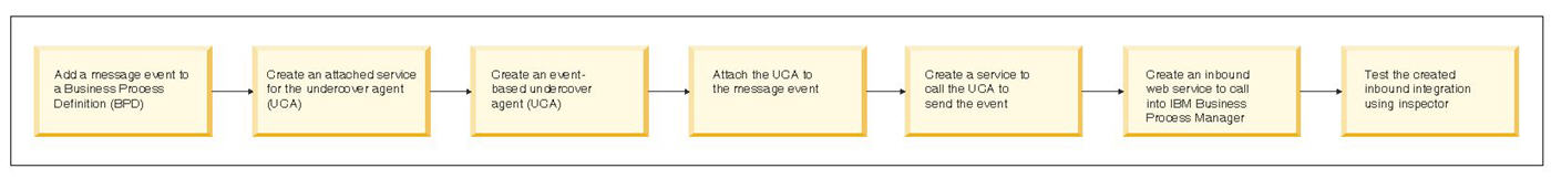
For general and introductory information, see Integrating with web services, Java and databases.
The following sections describe how to create simple components so that you can easily build the integration and also easily test your initial implementation. References to more detailed descriptions of the implementation options for each component are provided in the relevant sections.
You can call an undercover agent (UCA) using another business BPD, using a web service (and an associated caller service), or via JMS as illustrated in this sample. To learn how to establish message flow between two BPDs instead of using a service, see Use intermediate message events and message end events to send messages and Use message end events.
- Add a message event to a BPD Start building the sample integration by adding a message event to a business BPD.
- Create an attached service Create a service to pass parameter values from the message event to the business BPD.
- Create an undercover agent Create an event-based undercover agent (UCA).
- Attaching the undercover agent to the message event Attach the undercover agent (UCA) to the message event. The event waits for the completion of the UCA. When the UCA completes, the event completes.
- Create a caller service Create a service with appropriate inputs to call the undercover agent (UCA) to send the event.
- Create an inbound web service Create an inbound web service to provide a way for an external system or application to call into IBM Business Process Manager.
- Testing the integration Test the completed inbound integration using the Inspector.
Add a message event to a BPD
Start building the sample integration by adding a message event to a business BPD.
To build a sample inbound integration, you can start by adding a message event to a simple BPD as described in the following steps.
- Create a simple BPD that contains two activities like the one shown in the following image. (If you need detailed instructions, see Create a business BPD .)
- Drag an Intermediate Event component from the palette onto the BPD diagram so that it falls between the two activities.
- In the text box that displays over the event, type a name for the event. For this sample, you can type: Incoming Message Event.
- Click the Implementation option in the properties. The default implementation for Intermediate Events that are included in the process flow is Message.
- If not already selected, click the drop-down list and choose Receiving from the available message types.
- Use the Sequence Flow tool to connect the BPD components as shown in the following example:

Save your work.
Create an attached service
Create a service to pass parameter values from the message event to the business BPD.
The UCA that you attach to the message event needs a service to pass the parameter values from the runtime message to the BPD.
For intermediate message events like the one in this sample inbound integration, even if no parameter values are being passed from the message event to the BPD, you must map a UCA input variable to a local variable to ensure the correct running instance of the BPD resumes execution upon receipt of the message event.
- Create a General System service and name it My UCA Handler or something similar. (If you need detailed instructions, see Create a service.)
- Use the Sequence Flow tool to connect the Start Event and End Event components in the service diagram. Because this service is used to simply pass values, you do not need to add any service components to the diagram.
- Click the Variables tab.
- Click the Add Input button and replace Untitled in the Name field with someString.
- Leave the variable type for the input variable set to String.
- Click the Add Output button and replace Untitled in the Name field with someString.
- Leave the variable type for the output variable set to String.
Save your work.
Create an undercover agent
Create an event-based undercover agent (UCA).
The UCA tells IBM Business Process Manager what service to run when the message event is received. The message can be triggered by BPM itself or by an external system as in this example.
- In the Designer view, click the plus sign next to Implementation and then select Undercover Agent from the list.
- In New Undercover Agent, enter the following information and then click the Finish button.
- Name: Type My UCA or something similar for the name.
- Schedule Type: Select On Event from the drop-down list.
- In the Details section, the queue for processing this UCA is set to Async Queue by default. This setting is fine for the sample integration. (To learn more about the queue options, see Understanding and using undercover agents.)
- In the Parameter Mapping section, you can see the UCA is automatically mapped to the someString variable from the attached service, My UCA Handler.
Save your work.
Now the UCA is available, you can attach it to the message event.
Related tasks:
Understanding and using undercover agents
Attaching the undercover agent to the message event
Attach the undercover agent (UCA) to the message event. The event waits for the completion of the UCA. When the UCA completes, the event completes.
After you create the UCA, you should go back to the message event in the BPD and attach the UCA as described in the following steps.
- Open the BPD that includes the message event.
- Click the message event in the BPD to select it.
- Click the Implementation option in the properties.
- In the Message Trigger section, click the Select button next to the Attached UCA field and pick My UCA that you created in the preceding steps.
- Ensure the Consume Message and Durable
Subscription check boxes are enabled. (For more information about these options, see Modeling message events.)
If you occasionally use inbound messages, consider using durable subscription events. Durable subscriptions are Java Message Service (JMS) subscriptions that persist and store subscribed messages even when the client is not connected. The durable messages accumulate, even if you select the check box to make them consumable.
Periodically use the BPMDeleteDurableMessages
command for deleting durable subscription events.
- Click the Data Mapping option in the properties. Notice the Output correlation key is automatically set to the someString variable from the UCA. The variable is used as a correlation parameter, which allows you to correlate an event recipient with a particular key.
When an event occurs, that event must be matched against the correct instance of the process for which the event is destined. The ability to match the event against the correct instance is called correlation. Specify one variable in the message event that has a value that matches the value of the incoming event's UCA payload (the correlation value). If there is such a match, the message is received. If not, the message is not received, and the event continues to wait.
- In the field next to the variable, type tw.system.process.instanceId.
This sets the value of the someString variable to the ID of the running instance, which allows you to test the implementation in the Inspector.
In this example, you are creating a UCA that uses the current process instance ID as the correlation parameter. For example, if you have a process application with the instance ID of 50 and another process application with the instance ID of 100, if you invoke the UCA passing an ID of 50, only the first process application receives the event.
Save your work.
Understanding and using undercover agents
Create a caller service
Create a service with appropriate inputs to call the undercover agent (UCA) to send the event.
The next step in completing this sample inbound integration is to create an Integration service to call the UCA to send the event when the inbound web service (that you create in the following section) is called.
- Create an Integration service and name it Inbound WS Handler or something similar. (If you need detailed instructions, see Create a service.)
- Drag an Invoke UCA component from the palette, name it My UCA and place it between the Start Event and End Event in the service diagram.
- Use the Sequence Flow tool to connect the service components on the diagram.
- Click the Invoke UCA component in the diagram.
- Click the Variables tab, and then click the Add Input button to add the someString variable as an input variable.
Save the changes.
- Select the Implementation option in the properties.
- Click the Select button next to the Attached Undercover Agent field and pick the Undercover Agent that you created in the preceding procedure, My UCA.
- Select the Data Mapping option in the properties. The Input Mapping is automatically set to the someString variable from the UCA.
- In the field next to the variable, type tw.local.someString. This sets the input value of the UCA to the local value of the someString variable,
which enables you to test the implementation in the Inspector as instructed
in Testing the integration. The value is used in the business process definition correlation mapping created in the initial task.
The someString variable is available only if you create the attached service as instructed in Create an attached service and the UCA as instructed in Create an undercover agent before performing the steps in this procedure.
Save your work.
Create an inbound web service
Create an inbound web service to provide a way for an external system or application to call into IBM Business Process Manager.
Now you need to provide a way for an external system or application to call into IBM Business Process Manager. The recommended method for accomplishing this is to create and publish a web service endpoint so that external applications can initiate a particular BPM service or set of services by invoking an operation on the endpoint. By invoking a SOAP call, external applications can call the web service.
All operations that are exposed on an inbound web service are exposed as request-response operations. Even an operation bound to a service that has no outputs will be exposed as a request-response operation with no output. One-way operations are not supported.
The endpoint address for a web service is in the following format: http://host_name:port/[custom_prefix/]teamworks/webservices/process_app_name/[snapshot_name/]web_service_name.tws. If you do not specify the snapshot_name in the endpoint URL, it points to the tip snapshot for Process Center, or to the default snapshot for Process Server. To invoke a web service for a specific snapshot, make sure to specify the snapshot_name in the endpoint URL.
- Select the plus sign next to the Implementation category and then select Web Service from the list.
- In New Web Service, type KickTheBPD in the Name field and then click the Finish button.
- In the Operations section, click the Add button and select the Inbound WS Handler Integration service that you created in the preceding procedure from the list.
- In the Operation Detail section, change Untitled in the Operation Name field to doKick or something similar.
- Notice the WSDL
URI in the Behavior section. You can use this URI to test the sample integration as instructed in Testing the integration.
The Protected check box adds user name and password security to an operation in the web service. For a web service client to invoke a protected operation, the user ID and password added to the user name and password elements for this operation must be registered at the server, assigned to the process application and have at least read authority. Note that this is not authentication in the context of an HTTP transaction, so selecting Protected does not display a default user ID and password.
The Target namespace scheme drop-down list provides options for setting the target namespace:
- Per Process App/Toolkit settings (default): Uses the namespace from the Advanced XML Settings section of the Process App Settings page and does not include the snapshot name. This is the recommended setting as the target namespace will remain consistent when using multiple snapshots. Note the namespace must be already set at the time of this selection or Per snapshot name will be used. You will not be able to modify or update this value.
- Per snapshot name: Includes the snapshot name as well as the namespace from the Advanced XML Settings section of the Process App Settings page, if set. This scheme was used to define the target namespace before BPM 8.0.1. The target namespace value in your web service client will be different each time a snapshot is taken. You will not be able to modify or update this value.
- Custom: Lets you create your own target namespace in the Target namespace field.
If you select Per snapshot name, the namespace of the Web Services Description Language (WSDL) file is changed at least in the following cases. In these cases, the web service client must discover the WSDL file again so the namespace of the WSDL file is consistent between the web service client and server:
- The inbound web service uses a business object defined in the System Data Toolkit. The namespace of that business object uses a host name and a port specification. The web service client must discover the WSDL file again if the host name and port of the inbound web service is changed.
- The Target namespace schema field is changed to the Per snapshot name value. The namespace of the WSDL file uses the snapshot name after you select this option. The web service client must discover the WSDL file again for your inbound web service each time you create a snapshot.
- The Target namespace schema field is changed to the Per snapshot name value. The namespace of the WSDL file is changed if you change the snapshot from default version to non-default version on BPM server, or if you change the snapshot from the non-default version to the default version on BPM server. The web service client must discover the WSDL file again.
The namespace will be changed in the following cases. You must generate the types again for your inbound web service so that your namespace is consistent with the namespace on the server.
- The inbound web service uses a business object defined in the System Data Toolkit. The namespace of that business object uses a host name and a port specification. You must generate the types again if the inbound web service's host name and port is changed because of this situation.
- The Target namespace scheme field is changed to the Per snapshot name value. The namespace of the WSDL file will use the snapshot name once you select this option. You must generate the types again for your inbound web service each time you create a snapshot.
- The Security and Policy section allows you to configure a policy set and a policy binding with your web service. The server must have been already configured by a system administrator.
- Policy Set: Specifies the name of the application policy set. Click Select to choose the policy set. The list you will see depends on the policies available on the server. Some default application policy sets include: WSHTTPS default, WSAddressing default, and Username WSSecurity default. You can also additional application policy sets in the WebSphere Application Server Administrative Console. Deselecting a policy set also removes the policy binding. More information on policy sets can be found in the IBM Redbook WAS Web Services Guide.
- Policy Binding: Specifies the name of the general provider policy set binding, which contains system-specific configuration parameters like username and password information. Click Select to choose the policy binding. The list you will see depends on the general provider policy set bindings available on the server. Default policy set bindings include: Provider sample and Provider sample V2. You can also additional policy set bindings in the WebSphere Application Server Administrative Console. Deselecting removes the policy binding.
SOAP header information is available in system variables. The tw.system.soap.header.request variable is automatically initialized to contain the list of SOAP header entries found in the incoming request message. You can include JavaScript code with your inbound web service which accesses these SOAP header entries. You can also write JavaScript code which adds SOAP header entries to the tw.system.soap.header.response system variable. The SOAP header entries contained in this variable are added to the outbound response message.
Save your work.
Limitation: Any variable with a simple type containing a restriction element will not have the restriction element on generation of the inbound web service.
- Policy Set: Specifies the name of the application policy set. Click Select to choose the policy set. The list you will see depends on the policies available on the server. Some default application policy sets include: WSHTTPS default, WSAddressing default, and Username WSSecurity default. You can also additional application policy sets in the WebSphere Application Server Administrative Console. Deselecting a policy set also removes the policy binding. More information on policy sets can be found in the IBM Redbook
If you do not specify a snapshot name in the URI, then the default track is used to locate your web service. The tip in the default track is assumed to contain the process application with your web service. However, if you have your web service on a tip in a non-default track, it cannot be found. Therefore, create a snapshot name or make the track that you are working with the default track.
Related reference:
Supported web service standards
Testing the integration
Test the completed inbound integration using the Inspector.
After you build and link the input and output of the required components as instructed in the preceding procedures, you can test the completed inbound integration using the Inspector in Process Designer and a utility such as soapUI.
- Open the simple BPD that you created per the instructions in Add a message event to a BPD.
- Click the Run icon in the upper right corner of the BPD diagram. (If you need detailed instructions for using the Inspector, see Stepping through a process.)
- When IBM Business Process Manager prompts you to change to the Inspector interface, click Yes.
Click the check box if you want Process Designer to change interfaces without prompting for approval.
- From the Process Instances tab, click the received task for Step 1 and then click the run icon (). The coach for the activity, which is the default Human service, opens in a browser.
- Click the Done button in the Coach to complete the first step.
- Click the refresh icon () in the toolbar. You can see the process instance is waiting for the incoming message event.
- Use your SOAP utility, such as soapUI, point to the WSDL URI for the KickTheBPD inbound web service that you created per the instructions in Create an inbound web service.
- In your SOAP utility, initiate a request to the doKick method. In the someString parameter for the method, provide the Instance ID for the currently active instance, which you can see in the Process Instances tab in the Inspector. For example, in the preceding image, the instance ID of the active instance is 4.
- Click the Refresh icon in the Inspector toolbar. You should see that Step 2 has been received, meaning the message event was successfully processed and the instance is able to move to the next step.
- Click the Step 2 task to select it and then click the Run task icon. The value is used in the business process definition correlation mapping created in the initial task. If this value and the value of the BPD mapped variable are equal, the message intermediate start event runs. If not, the message intermediate start event continues to wait until a match is found.
- The Coach for the activity, which is the default Human service, opens in a browser. Click the Done button in the Coach to complete the second step.
- Click the Refresh icon in the Inspector toolbar. You should see the task for Step 2 is closed and the process instance has a status of Complete, indicating the BPD instance has completed successfully.
Create implicit SOAP headers for inbound web service integrations
SOAP headers are used to communicate application-specific context information within SOAP request and response messages. This context information can be anything that you must send along with the web service operation parameters. An implicit SOAP header is one that is not defined in the web service WSDL document. In an inbound web service integration, you can retrieve SOAP headers from an incoming request message and include SOAP headers in the outgoing response message.
- Retrieve SOAP headers from an inbound request message You can retrieve SOAP headers from an inbound request message by writing some JavaScript code to capture data from the tw.system.header.soap.request system variable.
- Add SOAP headers to an outgoing response message You can add a SOAP header to an outbound response message by using a system variable and some JavaScript code.
Retrieve SOAP headers from an inbound request message
You can retrieve SOAP headers from an inbound request message by writing some JavaScript code to capture data from the tw.system.header.soap.request system variable.
This task requires that you have access to an inbound web service integration that has at least one general system service associated with it. IBM Business Process Manager provides a system variable that you can use to retrieve SOAP headers. SOAP headers found in inbound request messages are automatically copied to the tw.system.header.soap.request system variable. You can write code to retrieve those SOAP headers.
To retrieve SOAP headers from an inbound SOAP request message, write JavaScript code that uses the tw.system.header.soap.request system variable. You can add a component, such as a server script component, to your general system service. You can then add your JavaScript code to this component's Properties view within the Pre-execution or Post-execution Assignments section or within the Implementation section. Alternatively, you can add the code to any location that is part of the general system service for the endpoint.
In this example, the code example is retrieving a header named subscriptionInfo of type SOAPHeader from the system variable tw.system.header.soap.request. If the request message contains SOAP headers, this variable will be initialized to contain them. If the request message does not contain SOAP headers, this variable will be null.
log.info(">>>>>> Checking to see if the subscriptionInfo SOAP header was received in the request message...")

var subscriptionInfoHeader = null
if (tw.system.header.soap.request != null) {
    for (var i = 0; i < tw.system.header.soap.request.headers.listLength; i++) {
        // search for the subscriptionInfo header        if (tw.system.header.soap.request.headers[i].name == "subscriptionInfo") {
           subscriptionInfoHeader = tw.system.header.soap.request.headers[i]
       }
   }}

if (subscriptionInfoHeader != null) {
    log.info("Found the subscriptionInfo SOAP header!")}
else {
    log.info("The subscriptionInfo SOAP header was not present in the request message.")}
Assume the following SOAP header is in a request message:
- <ns1:subscriptionInfo xmlns:ns1="http://acme.com">1234-56-7890-fc3a</ns1:subscriptionInfo>
The following output is produced by the code in that example:
- Found the subscriptionInfo SOAP header!
Add SOAP headers to an outgoing response message
You can add a SOAP header to an outbound response message by using a system variable and some JavaScript code. IBM Business Process Manager provides a system variable that allows you to add SOAP headers to an outbound response message, tw.system.header.soap.response. You can instantiate the tw.system.header.soap.response variable from the Variables tab above the process diagram or in the JavaScript code.
To add a SOAP header to an outbound response message, add an entry to the SOAPHeaders array within the tw.system.header.soap.response system variable. You can add the code to the Pre & Post > Post-execution Assignments section within a component of a general system service, such as a server script component.
To add a header that is called sessionToken to the response message, use JavaScript code such as the following example. Follow these best practices as you write your code:
- Make sure namespaces are fully qualified, as they are in the following examples.
- Avoid white spaces in the XML snippet that constitutes the SOAP
header value.
- Make sure that you only instantiate the tw.system.header.soap.response variable if it is null. Otherwise, you could end up clearing out SOAP header entries that were added by some other component within your general system service.
log.info(">>>>>> Adding a SOAP header to the response message...")

// Create the header object var myResponseHeader = new tw.object.SOAPHeader()
myResponseHeader.name = "sessionToken"
myResponseHeader.nameSpace = "http://acme.com"
myResponseHeader.value = "<x:sessionToken xmlns:x=\"http://acme.com\">abdf-128974-33-33-fcea-10243-74-33</x:sessionToken>"

// If the response header system variable doesn't exist yet,
// then you must instantiate it if (tw.system.header.soap.response == null) {
     tw.system.header.soap.response = new tw.object.SOAPHeaders()
     tw.system.header.soap.response.headers = new Array()
 }

// Determine which index we need to use when adding the new header entry.
//Add the new header at the end of the array so the processing does not // overwrite any existing entries.
var nextIndex = tw.system.header.soap.response.headers.listLength
log.info("Adding new header at index: " + nextIndex)
tw.system.header.soap.response.headers[nextIndex] = myResponseHeader
Use the next available index when adding your new SOAP header entry to the tw.system.header.soap.response variable "headers" field, which is an array of SOAP header values. Otherwise, you might inadvertently clear out an existing SOAP header entry that was added by some other component within your general system service.
Posting a message to IBM Business Process Manager Event Manager
To create post a message from an external system to BPM Event Manager, use the message structure described in this topic.
You can use Java Message Service (JMS) to post a message to the Event Manager. See Maintain and monitor IBM Business Process Manager Event Manager to learn how the Event Manager processes incoming requests.
Understanding the message structure
The message that you post to the Event Manager must contain an event name (the message event ID generated when you create an Undercover Agent) and it can contain parameter names and values in key-value pairs. ( Configure an undercover agent for a message event describes the message event ID that you should use for the event name.) The message must be structured as XML as shown in the following example:
- <eventmsg> <!-- The process app acronym and event name are required: The snapshot and UCA name are optional --> <event processApp="[acronym]" snapshot="[snapshot_name]" ucaname="[UCA_name]">[event_name]</event> <!--Optional: The name of the queue for the event to run in--> <queue>[queue name]</queue> <!--Any parameters the UCA may require-- <parameters> <parameter> <key>param1</key> <value><![CDATA[value1]]> </value> </parameter> </parameters> </eventmsg>
If you do not include the snapshot name in the message, the Event Manager uses the default snapshot on the target Process Server for start message events. For intermediate message events, if you do not include the snapshot name in the message, all active snapshots receive events. To learn more about active and default snapshots, see Configure runtime settings for installed snapshots .
Note that if the value of the <value> element contains XML elements or similar content, you need to wrap the value in a CDATA tag as shown in the preceding example. For information about passing parameter values for each complex business object (variable type), see the following section.
Passing complex variable types to Undercover Agents
You can use Undercover Agents (UCAs) to instantiate services and BPDs automatically, without human interaction by an BPM participant. When you include a Message Event in an BPM BPD, assign a UCA to it for the Message Event to run at run time. The Event Manager, which is part of the Process Server, handles the scheduling and queuing of UCAs. See Understanding and using undercover agents .
In addition to user-created complex business objects (variable types), the following complex business objects can be used to invoke UCAs at run time:
| width="NaN%">Variable type | width="NaN%">Syntax |
|---|---|
| Record | XMLDocument |
| Date and Time | XMLElement |
| Boolean | XMLNodeList |
| Map | ANY (default) |
For example, to invoke a UCA using an XML message, let's say the runtime process contains a Message Event that waits for an incoming message. This message contains an input parameter whose value includes the Customer Name, Description, and Age.
First, create the service and then associate the service with an Undercover Agent (the service describes what happens when the UCA is invoked at run time). Then, send the message with the following syntax:
- <eventmsg> <event processApp="[acronym]" snapshot="[snapshot_name]" ucaname="[UCA_name]">[event name]</event> <parameters> <parameter> <key>customerParam</key> <value> <Name>John</Name> <Description>John Description</Description> <Age>30</Age> </value> </parameter> </parameters> </eventmsg>
The following sections provide examples of how to pass the content of the <value> element. The conversion from the event XML format to a complex type is handled automatically by the BPM engine.
When the Any type is used to pass a parameter value, the actual BPM type must be supplied using the type attribute of the corresponding element. The type attribute can be omitted only when BPM knows the exact type or when the type is String. The value of the attribute must be an existing BPM type-or in case of an array, an BPM type concatenated with the [] string at the end.
Passing BPM Structured types
All structured objects are passed as XML structures, where every object property corresponds to an XML element.
For example:
Variable type: Customer - Name: String (John Doe) - Description: String (Single) - Age: Integer (30)
is mapped to:
- XML: <value> <Name>John Doe</Name> <Description>Single</Description> <Age>30</Age> </value>
Keep the following important rules in mind:
- Every object property is mapped to an XML Element with the same name as the property name. The element name is case sensitive. For example, if the property is Name, the element name must be <Name>, not <name>.
-
All XML element attributes are reserved. If you pass an attribute (excluding type), an error is returned because the passed Document is not valid.
-
When an array is passed, it is mapped as a sequence of XML elements with the same name. There are two possibilities:
Passing root level arrays: Every object array item must be placed as content of an <item> element. For example:
- <value> <item> <Name>John Doe</Name> <Description>Married</Description> <Age>30</Age> </item> <item> <Name>Jane Doe</Name> <Description>Married</Description> <Age>31</Age> </item> </value>
Passing array properties: Every object in the object array is converted to XML using the object property name as an XML Element name. For example:
- <value> <Name>John Doe</Name> <Description>Single</Description> <Age>30</Age> <Address> <Street>10506 Jollyville Rd</Street> <City>Austin</City> </Address> <Address> <Street>10507 Research Blvd</Street> <City>Austin</City> </Address> </value>
-
If an object property is null , the corresponding element is skipped.
Passing Record type
The Record type is serialized in the same way as Structured types. However, because all values are considered of type ANY , the type information must also be passed (using the type attribute) in order for the correct objects to be instantiated during de-serialization.
Passing Date/Time types
The format for passing dates is yyyy/MM/dd HH:mm:ss.S z .
Example:
-
<value>2004/03/11 14:02:20.0 PST</value>
-
<value>2000/02/20 11:10:20.0 GMT+6:00</value>
When the value is converted to the Calendar Java object, it preserves the time zone, and no other modifications (such as adjusting it to the server time zone) is performed.
Passing Boolean type
The valid values for the Boolean type are true or false(case is not considered).
Example:
<value>TRUE</value>
Passing Map type
A Map type is passed to a UCA using the following structure:
- <value> <entry> <key> … </key> <value> … </value> </entry> </value> For example: <value> <entry> <key>TX</key> <value>Texas</value> </entry> <entry> <key>CA</key> <value>California</value> </entry> </value>
Because all values and keys in this case need to be of the ANY type, the type information must also be passed in order for the correct objects to be instantiated during deserialization. If the object is of the String type, the type does not need to be specified.
Passing XMLDocument type
An XML Document is passed as an XML escaped string.
Example:
- <value> <![CDATA[ <?xml version="1.0"?> <Customer> <Name>John Doe</Name> <Description>Married</Description> <Age>30</Age> </Customer> ]]> </value>
Passing XMLElement type
An XML Element is passed as an XML escaped string.
Example:
- <value> <![CDATA[ <Customer> <Name>John Doe</Name> <Description>Married</Description> <Age>30</Age> </Customer> ]]> </value>
Passing XMLNodeList type
Every node is passed as an XML escaped string. The array of the nodes is encoded as a sequence of <item> elements.
Example:
- <value> <item> <![CDATA[ <Customer> <Name>John Doe</Name> <Description>Married</Description> <Age>30</Age> </Customer> ]]> </item>| <item> <![CDATA[ <Customer> <Name>Jane Doe</Name> <Description>Married</Description> <Age>31</Age> </Customer> ]]> </item> </value>
Passing ANY type
When the type of an input parameter to a UCA is declared as ANY , the information about the actual type must be passed as part of the XML.
Example:
Define a process with one input parameter, Name , of type ANY . When the data is encoded in XML, the actual type must be supplied as the value for the type attribute. If the type is not passed, the String type is assumed.
- <value type="String"> John Doe </value>
Publishing IBM Business Process Manager web services
BPM can publish web services in the same way that it consumes web services. Using a SOAP connection, external applications can call the BPM web service to initiate a particular service or set of services.
You can create and publish a web service to enable external applications to initiate a particular BPM service or set of services. Using a SOAP integration, external applications can call the web service.
See Building a sample inbound integration to learn how to build a sample integration that includes a web service.
Follow these steps to create a web service that external applications can call:
- Start Process Designer and open the appropriate process application in the Designer view.
- In the Designer view, select the plus sign next to the Implementation category and then select Web Service from the list.
- In the New Web Service window, type a name for the service and then click the Finish button.
- In the Common section, you can type a description of the web service in the Documentation text box.
- In the Operations section, click the Add button to choose an existing service to add. Because the services that BPM initiates from a web service do not have an associated task, do not add services that include the following components: Coach, Modify Task, and Browser Script. See Understanding service components for more information about these components.
- Under Operation Details, type a name for the selected service in the Operation Name text box. (Change Untitled to the name that you want.)
- Optionally, you can type a description of the operation in the Documentation text box.
- Click the Add button in the Operation section to continue adding services.
- In the Behavior section, enable the Protected check box if you want access to the WSDL URI to be password-protected. If password-protected, a user must supply a user name and password to access the operations described in the WSDL URI.
- In the Behavior section, click the WSDL URI to view the XML description of the resulting web service and its elements and operations. You can supply this URI to the developers who need to call the operations within the web service.
- Include a Message Event in your BPD for the incoming request as described in Modeling events .
- Create an Undercover Agent (UCA) that calls this web service as described in Understanding and using undercover agents and then attach the UCA to the event from the preceding step.
When you install a process application on a test or production server, all web services are included in the list of exposed items in the Process Admin Console.
Web services compatibility
Web services conform to a flexible architecture that allows variation in web services implementations. This variation unfortunately can lead to compatibility problems.
If you are experiencing problems when you call an external web service from a business process, you should first check its compatibility with BPM. In XML constructs not supported, these compatibility problems are outlined and explained. Tables are provided that list errors and warnings caused by incompatibilities. Once you know the source of the cause you can correct the web service accordingly.
If you are using IBM Business Process Manager Advanced and experiencing web services difficulties associated with incompatibilities, consider using an Advanced Integration Service to give you access to Integration Designer. The web services tools in Integration Designer have a variety of popular bindings and features that can be used to handle most web services interactions.
You also have another alternative, particularly if you have IBM Business Process Manager Standard, and that is to use a SOAP connector. In the following sections, which show this approach, it is assumed that you have access to a service using Web Services Description Language (WSDL) and that you can make a call to the web service using the soapUI open source tool or another SOAP tool. These instructions describe testing the web service with soapUI.
Note that IBM Business Process Manager Standard has the following restrictions:
- SOAP header: There is only support for a request SOAP header that passes complex type parameters. There is no support for a SOAP header, either request or response, that passes simple type parameters.
- SOAP / JMS: SOAP over JMS is not supported.
- SOAP faults are not supported.
- HTTP headers are not supported.
- The Remote Procedure Call (RPC) binding style is not supported.
- Verifying the web service is working First check the web service is working. The web service must be working before you can call it from a business process.
- Use a SOAP connector to call a web service Once you know the web service works, you should test it from within Process Designer.
Supported web service standards
Verifying the web service is working
First check the web service is working. The web service must be working before you can call it from a business process. These steps let you determine if you have a proper, working URL containing the expected WSDL file.
You can see the following steps with screen captures from a previous version in this technote.
- Verify that you have a live WSDL URL.
- Paste the URL into a browser window. You may need to add ?WSDL to the end or your URL. If the URL is not working, you are likely lacking the correct network configuration to access the web service.
- Install soapUI using the default configuration.
- Right-click Projects and click New soapUI Project.
- Paste your WSDL URL into the box labeled Initial WSDL/WADL. Do not change the other values and options and click OK. You should now have a sample call for your web service where you can make sample calls based on XML input.
- Test the web service by replacing question marks with actual data inputs and press Play. There are hints provided by soapUI in places where repeated entries or optional entries exist. For these entries, deleting items should not be a problem.
Use a SOAP connector to call a web service
Once you know the web service works, you should test it from within Process Designer. These steps show you how to test your web service.
You can see the following steps with screen captures from a previous version in this technote.
- Create a new Integration Service. Select Implementation > +. From the menu, select Implementation Service.
- In the dialog that opens, enter a name and click Finish.
- Beneath TOOLKITS, expand SystemData and select Implementation. Locate the Call WebService via SOAP component and drag it onto the diagram.
- Drag a Server Scriplet from the right-side palette to your diagram. Place it to the left of Call WebService via SOAP.
- Connect the lines. Start should connect to the Untitled server scriptlet. The Untitled server scriptlet should connect to Call WebService via SOAP. Call WebService via SOAP should connect to End.
- Select the Call WebService via SOAP component.
Select the Data Mapping tab in the Properties view.
You should be able to identify all of the inputs required except for the request input.
- wsdlURL maps to the URL address.
- serviceNS maps to the targetNamespace value.
- serviceName maps to the service name value.
- destinationAddress maps to the soap:address location value.
- soapAction maps to the soap:operation soapAction value.
- The request input includes your variable inputs. In this example, we use the server scriptlet to create the XML input.
- Open the variables tab and create a new private variable called request with an XMLElement type.
- Return to the diagram view and rename the server scriptlet to Set Request.
- Select the Implementation tab from the Properties view for the server scriptlet and bind the implementation to your request variable. Click Select and click the request variable from the menu.
- Copy your entire XML input from soapUI and paste it into the server scriptlet implementation.
- Bind your request variable to the request input of the SOAP Connector. Return to the Data Mapping section of the Call Web Service via SOAP component and, using Select, map request (XMLElement) to the request variable you just created.
- In a similar manner, create a variable called response of type XMLElement, and bind it to the output of the SOAP Connector; that is, the Call Web Service via SOAP component. At this point, you should be able to test your service using hard-coded values.
- Run the service in debug mode to see the response placed
into your response variable. If it worked correctly, you are ready to add input variables to your service and map them into your request variable in the server scriptlet. The following example only has one input:
- Add an input variable to your service.
- Use <#= #> notation to include JavaScript in your server scriptlet. For example if your input variable was degreesF. the implementation code referring to it would be <# = tw.local.degreesF #>. Now your service input will determine the input to the SOAP Connector.
- Add an input variable to your service.
- Use Xpath to map your response variable into proper outputs.
This example uses a single output variable (_degreesC).
- Add a Server Script to the end of your service
- Use Xpath to map the XML response into the output variables.
For example:
- This Xpath expression returns a node list of all 'Page' nodes until the VisioDocument/Pages node:
- xml.xpath("VisioDocument/Pages/Page");
You might need to experiment with having or not having a slash at the beginning depending on the structure of the XML.
- This Xpath expression returns a node list of all 'Master' nodes that have the NameU attribute equal to 'Horizontal holder':
- xml.xpath("VisioDocument/Masters/Master[@NameU='Horizontal holder']");
- In either case, you need to know the node path and namespace.
The following Xpath expression ignores the depth and ignores namespaces.
It is the same as i, except it ignores namespace and depth of 'Page'
node:
- xml.xpath = "//*[local-name()='Page']";
In any case, the result is a nodelist that can be used something like:
var nodeList = xml.xpath(...);
tw.local.objArray = new tw.object.listOf.myObj();
 var obj = new tw.object.myObj();
 //If name node always exists as a child  obj.name = nodeList[i].name[0].getText();
 tw.local.objArray[tw.local.objArray.listLength] = obj;}
- This Xpath expression returns a node list of all 'Page' nodes until the VisioDocument/Pages node:
- Add a Server Script to the end of your service
Globalization
To ensure that applications can be used in multiple geographical locations and cultures, globalization support is built in through appropriate design and implementation of systems, software, and procedures. IBM Business Process Manager provides globalization support for single- and multi-byte character sets and for bidirectional transformation including contextual support, support for text layout transformation, and calendar support for Hebrew and Hijri.
- Bidirectional support in BPM Scripts such as Hijri and Hebrew, where the general flow of text proceeds horizontally from right to left, are called "bidirectional" scripts. The attribute "bidirectional" (bidi) is used for scripts, but by association, the languages that use bidirectional scripts are called bidirectional languages. Although bidi text runs in both directions, the right-to-left direction is the norm.
- Contextual support BPM offers contextual bidi support for languages such as Arabic and Hebrew, where the general flow of text proceeds horizontally from right to left.
- Support for text layout transformation BPM provides bidirectional (bidi) text layout options for process design.
- Calendar support for Hebrew and Hijri BPM provides calendar support for Hebrew and Hijri calendars.
Bidirectional support in
Scripts such as Hijri and Hebrew, where the general flow of text proceeds horizontally from right to left, are called "bidirectional" scripts. The attribute "bidirectional" (bidi) is used for scripts, but by association, the languages that use bidirectional scripts are called bidirectional languages. Although bidi text runs in both directions, the right-to-left direction is the norm.
- If the direction of the window is right to left, its elements are logically ordered from right to left and from top to bottom.
- Within a right-to-left window, the default direction of entry fields is right to left, but entry fields that are to receive English text or numeric input must be defined as having a left-to-right direction.
- Within the same window, text and graphics can have different directions.
BPM provides built-in bidirectional (bidi) layout options for designing processes. Bidirectional support in BPM includes the following features:
- Contextual typing
- Layout transformation in Process Designer
- Hijri and Hebrew calendar support
Contextual support
BPM offers contextual bidi support for languages such as Arabic and Hebrew, where the general flow of text proceeds horizontally from right to left.
Contextual support ensures that when a first typed character is Hebrew or Arabic, control orientation and typing direction are right-to-left, and the text alignment is right. The following is a list of the different kinds of contextual support that BPM provides.
- Contextual support for names of diagram elements ensures correct display of bidi text not only in properties but also in diagram.
- Contextual support in notes ensures right-to-left text direction of text inside the notes.
- When a new activity is dragged from the palette and dropped onto the business process diagram canvas, contextual typing of the activity name is possible inside the business process diagram.
- Contextual typing is supported in descriptions in Process Center.
Support for text layout transformation
BPM provides bidirectional (bidi) text layout options for process design. Complete the following steps for bidi text layout transformation:
- Start with a simple process diagram that includes Start > Human service > End.
- Insert a simple human service with one coach preceded by a user task. The user task is the key element to implement the bidi text layout transformation. This user task is a JavaScript, whose variables can be set and modified by using the Properties panel.
- Select the user task in the diagram, and provide an input string variable for the user task in the Properties panel, for example, var1.
- Create a coach with a single input field with bindings to variable var1.
- In the Implementation tab of the Properties panel, provide the script for calling the bidi engine to implement the transform user task. The call API is as follows: tw.local.Var
= tw.system.bidiTransformation(tw.local.Var,"input_bidi_format", "outputBidiFormat",
symmetricSwapping), where tw.local.Var1 is string to be transformed.
The input BidiFormat and output BidiFormat can have the following values:
- LLTR - logical left-to-right
- LRTL - logical right-to-left
- LCLR - logical contextual left-to-right
- LCRL - logical contextual right-to-left
- VLTR - visual left-to-right
- VRTL - visual right-to-left
- VCLR - visual contextual left-to-right
- VCRL - visual contextual right-to-left
In this example, isSymmetricSwapping is a Boolean variable. The call to bidi engine displays as follows:
tw.local.Var1 = tw.system.bidiTransformation(tw.local.Var1,"LLTR", "LRTL", true)
Bidirectional text layout transformation can be applied to any string variable (either input or output) as part of preprocessing, postprocessing, or implementation of a specially created human task. Typically, bidirectional text layout transformations are required for conversion of bidi textual data stored in the databases to a Logical LTR format assumed by the BPM user interface, but can be used for other purposes.
- Run the coach.
Calendar support for Hebrew and Hijri
BPM provides calendar support for Hebrew and Hijri calendars.
Hebrew and Hijri calendars work with the Coaches for the date selector functionality.
- Open Process Designer.
- In the Presentation tab, select Hebrew or Hijri in the National Calendars list.
- Run the Coach. The Hebrew or Hijri calendar is displayed in the date selector, instead of the Gregorian calendar.
- You can also select the Hebrew or Hijri calendar type in the process portal preferences, and then select User Default. The Hebrew or Hijri calendar is displayed in the date selector, instead of the Gregorian calendar.
Create user interfaces for business processes
Users interact with a IBM Business Process Manager process through human services.
There are two types of user interfaces for human services: task completion and dashboards. A task completion user interface implements a specific activity within a process instance. It has access to the details of that process instance. For information, see the User Task implementation option in Implementing activities and see Building a Human service. A dashboard is a stand-alone user interface that users can run at any time. Users can access dashboards through the Process Portal. For information about dashboards, see Dashboards in Process Portal. You can also use a Coach-based dashboard as a WebSphere portlet. For information, see Generating portlets for human services exposed as dashboards.
To build either type of user interface for human services, you use Coaches or Heritage Coaches. Coaches are composed from user interface controls called Coach Views. You can create Coach Views in Process Designer. For information, see Coaches and Coach Views. Heritage Coaches are composed from a fixed set of user interfaces controls. They are primarily for compatibility with BPM before version 8.0. For processes created with BPM v8.0 and later, Coaches are recommended.
- Coaches Coaches are the user interfaces for human services.
- Introduction to Coaches and Coach Views in BPM This is the transcript for the viewlet "Introduction to Coaches and Coach Views" video, which demonstrates the relationship among Coaches and Coach Views.
- Difference between Coaches and Heritage Coaches The Coaches in V8.5 of IBM Business Process Manager are different in construction than the Coaches in V7.5.1 and previous versions of BPM.
- Dashboards A dashboard is a user interface that displays business process information. Authorized users use the dashboard to interact with that information.
- Building Coaches You can build a Coach as the user interface that process participants use to interact with a service.
- Developing reusable Coach Views To contain functions or user interface elements that another Coach View or a Coach can use, create a Coach View.
- Enable JavaScript debugging for Coaches For debugging purposes, you can set your Coaches and Coach Views to use the readable versions of Dojo and the Coach framework JavaScript.
- Stock controls Stock controls are Coach Views that are included with BPM . They are in the Coaches (SYSC) toolkit.
- Stock content controls Stock content controls are Coach Views that are included with BPM. They are contained within the Content Management (SYSCM) toolkit.
- Coach and Coach View examples This documentation includes a number of examples that demonstrate how to create and code the various parts of Coaches and Coach Views.
- Coach and Coach View reference information The following topics contain reference information for Coaches and Coach Views.
- Dashboard controls Dashboard controls are Coach Views that are included with BPM in the Dashboards toolkit.
- Building Heritage Coaches When you build human services you can use Heritage Coaches, which provide the interfaces for end-user interaction.
Coaches
Coaches are the user interfaces for human services.
There are two types of user interfaces for human services: dashboards and task completion. To build either type of user interface for human services, you use Coaches.
When a Coach is a dashboard user interface, users can run it as a stand-alone user interface at any time. The users access it through the Process Portal. For information about dashboards, see Dashboards in Process Portal. Users can also access it as a WebSphere portlet. For information, see Generating portlets for human services exposed as dashboards.
For an introductory video about Coaches and Coach Views, watch "Introduction
to Coaches and Coach Views in BPM", available on YouTube or the IBM Education Assistant information center.
A transcript of the video is available.
When a Coach is a task completion user interface, it is part of the human service flow. At run time, when the flow enters the Coach, the user sees the user interface defined for that Coach. The user interface consists of HTML code that is displayed in a web browser. The flow leaves the Coach when a boundary event occurs. A Coach can have multiple exit flows with each one associated with a different boundary event.
Coaches contain one or more Coach Views. The Coach Views provide the user interface elements and layout for the Coach. Each Coach View can contain one or more other Coach Views, which creates a parent-child relationship between these Coach Views. At run time, the parent Coach View is rendered as a <div></div> tag that contains a nested <div></div> tag for each child Coach View. Each Coach View can also have a binding to a business object, CSS code to control its visual layout, and JavaScript to define its behavior.
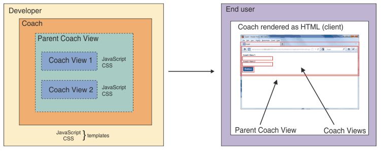
Coach Views are reusable so you can create a library of common user interfaces and behavior. You can combine these common user interfaces to rapidly develop new Coaches. The Coaches toolkit that is included with BPM contains a set of common user interfaces that are called stock controls. You can include these stock controls when you are creating your own Coach Views.
To maintain compatibility with earlier Coaches, BPM supports Heritage Coaches. A Heritage Coach has the technology and architecture of a Coach in versions of BPM before V8.0. A human service can have Coaches or Heritage Coaches. You can continue to use and maintain Heritage Coaches, but use Coaches for new user interfaces for services.
Related concepts:
Difference between Coaches and Heritage Coaches
Related tasks:
Developing reusable Coach Views
Difference between Coaches and Heritage Coaches
The Coaches in V8.5 of IBM Business Process Manager are different in construction than the Coaches in V7.5.1 and previous versions of BPM.
The primary difference between Coaches and the Heritage Coaches of previous versions is that Coaches consist of one or more Coach Views. Coach Views are reusable collections of user interfaces that are frequently bound to a data type. This means that you can share common pieces of user interface between Coaches. For example, you can create a Coach that has a Coach View that contains a set of address fields. That is, the Coach View is bound to an Address business object and the individual text fields are bound to parameters of that business object. If you create a second Coach that needs address fields, you can reuse the Coach View. Conversely, with Heritage Coaches you must re-create the address fields. You can now implement your own custom controls as Coach Views and then reuse these custom controls in other Coach Views and Coaches.
Another key difference is the introduction of a client-side model to Coaches to apply the Web 2.0 appearance and behavior. The Coach has data on the client, which is available to all of the Coach Views. That is, fields in different Coach Views that are bound to the same data object update without requiring a full-page refresh. The Coach framework and the stock control Coach Views use Dojo 1.8.3.
Instead of the one-button mechanism of Heritage Coaches, Coach Views use named boundary events. Programmers use boundary events for actions such as data updates with the server and transitions to other Coaches or services. For example, a Coach can have multiple buttons. In the human service diagram, you can wire each button to a different event. Any Coach View can declare and fire a boundary event. You are not limited to using only buttons to do so although, of the stock controls, only the button stock control can fire a boundary event. Furthermore, the programming for Coach Views consists entirely of client-side JavaScript. There is no need for server-side JavaScript.
Coaches support collaboration while Heritage Coaches do not. More than one person can work on the same Coach instance at the same time in their own browsers. For example, with collaboration, users can call on colleagues to help them complete a Coach instance. These users see which controls their colleagues are editing and the values they are setting in those controls. Collaboration is available only if the service flow uses Coaches for its user interface. If the service flow contains one or more Heritage Coaches, collaboration is not available.
The control ID of a view-based Coach is different from the control ID of a Heritage Coach. The control ID of a Heritage Coach is the div node ID. This is not the case in view-based Coaches because Coach Views are reusable and you can have multiple views in a Coach. In view-based Coaches, the control ID is the value of the data-viewid attribute of a <div></div> tag. By using the data-viewid attribute, View developers can locate the nested View because data-viewid is unique within its parent or enclosing view.
In BPM, services use Coaches and Heritage Coaches for the user interface. A service flow can mix Coaches and Heritage Coaches so that one type can flow into the other. However, a Coach cannot contain Heritage Coach elements and Heritage Coaches cannot contain Coach Views. That is, a user interface must be a Coach or Heritage Coach and not a mix of the two.
Visually, Coaches resemble Heritage Coaches in human service diagrams and on the palette.
| Coach | Heritage Coach |
|---|---|
|
|
|


When you open or edit a Coach, you can see the user interface and palette for BPM V8.0. However, services that were created in previous versions can continue to use their existing Heritage Coaches. In addition, you can edit these Heritage Coaches in V8.0 to update them. You do not need to migrate your Heritage Coaches. When you open or edit a Heritage Coach, you can see the user interface and palette from V7.5.1. When you open a Coach to edit it, you might notice a number of key differences from the earlier Heritage Coach:
- The palette contains Coach Views that you can drop into the Coach. Although there are stock controls and other palette items that have the same name in Heritage Coaches, these items are implemented differently.
- The palette uses tags to categorize the Coach Views that are available. You can use the filter to show or hide the categories of Coach Views.
- The properties area of the Coach View elements have different pages from the controls and sections of Heritage Coaches. However, many of the properties in Heritage Coach controls have a corresponding property in Coach Views. For example, the page named after the Heritage Coach control contains properties such as Label, Binding, and Control Id. In Coach Views, you can find corresponding properties on the General page. Many of the Heritage Coach presentation properties have a corresponding Coach configuration option. Even when Heritage Coach controls and Coach Views have properties that have the same name, the implementation of those properties can be different.
Related concepts:
Related tasks:
Developing reusable Coach Views
Dashboards
A dashboard is a user interface that displays business process information. Authorized users use the dashboard to interact with that information.
A dashboard displays data from one or more business processes. Although the dashboard can display the data in many different ways, typically it uses charts, graphs, and other visualization user interfaces. A dashboard can also contain other content.
Use dashboards, users can see an overview of the data or filter it to concentrate on a particular aspect. If usingrs have the appropriate permissions, they can use the dashboard to interact with the data. For example, a graph in a dashboard shows all the business processes. It identifies which processes might need attention because they have process instances that are at risk or overdue. A process owner can use the dashboard to identify the problem and then act in a way that enables process instances to finish on time. Similarly, team leaders can use a dashboard to check the status of work items and reassign work to balance the workload between team members.
Users can access a dashboard by using IBM Process Portal. Process Portal provides access to many dashboards, work interfaces, and user preferences from one URL. It includes several standard, ready-to-use dashboards that help you analyze and manage your business processes. These standard dashboards include the following dashboards:
- Team Performance
- Process Performance
In addition, the Process Portal installation might include company-specific dashboards to help you manage other aspects of business processes. A business programmer or analyst creates these dashboards by exposing human services and by using the Coaches of those human services as the user interfaces of the dashboard.
If an administrator exposes the dashboard as a URL, users can access the dashboard outside of Process Portal. Users can also access the dashboard as a portlet for WebSphere Portal.
Related concepts:
Related tasks:
Building Coaches
You can build a Coach as the user interface that process participants use to interact with a service.
In the first stage of designing a Coach, your goal might be to build a mock-up. The mock-up contains static elements to visualize what data the Coach needs at run time and where the Coach displays the data in its layout. After you complete the first stage to design the look of the Coach, you then feed real business data to the Coach controls. This step requires you to create bindings between the Coach controls and the data structures (variables) that represent the business data in your IBM Business Process Manager processes. Your process participants can then interact with the business data, which helps them make the appropriate decisions.
Building a Coach is often an iterative process in which you loop back to refine the Coach as you build it. Although you can do some of the steps in any order, in general you take the following steps:
- Create one or more mock-ups for the Coach. Use the mock-ups to identify elements in the Coach that are common with other Coaches.
Identify the following information:
- The elements in the Coach that are reusable.
- The best layout for the user interface elements in the Coach.
You can then use this information to decide which parts of the Coach you can implement as reusable Coach Views. For example, after you create the mock-up, you see that your Coach contains two sets of identical address fields. Instead of creating the two sets of address field in the Coach, you create one address field Coach View. You can then use it for both sets of address fields.
- If there are toolkits that contain artifacts that your Coach can use, add a dependency to these toolkits. These artifacts include business objects, Coach Views, and files. These artifacts include business objects, Coach Views, and files. The dependency is to a particular snapshot of the toolkit. If you are revising an existing Coach, you can upgrade the dependency to a different snapshot of the toolkit. The upgrade is optional. If you do not do the upgrade,
the Coach continues to use the existing dependency.
The Coaches 8.5 toolkit uses Dojo 1.8.3 with AMD (Asynchronous Module Definition). If you upgrade the Coaches toolkit to version 8.5.0, review the Coaches in the process application to assess the impact of the upgrade in Dojo version.
- If the Coach Views that your Coach will use do not exist, create them. For information, see Developing reusable Coach Views.
- In the human service diagram, add the Coach to the diagram and then double-click it to edit it.
- Drag Coach Views or variables onto the layout of the Coach. These Coach Views can be the Coach Views
that you created earlier or the stock controls. The variables are business objects and their parameters that are defined for the human service . For the variables, the Designer puts the Coach View that is associated with the business object or parameter type onto the layout. For example, if you drop variable that is of the String type, the Designer puts a text stock control that is bound to the variable. If the variable type does not have an associated Coach View, the Designer puts a placeholder message on the layout instead. You can then use the placeholder to manually specify the binding between the variable and a Coach View.
For examples of dragging a Coach View and variables onto a Coach, see Example: creating a tabbed Coach.
For elements in the Coach that you do not plan to reuse, you can drop the appropriate palette component onto the Coach. For example, for text instructions for the user, you can drop an HTML element and add the text as HTML code. You can also drag fields within a variable directly onto the Coach.
- To lay out the Coach Views in the Coach, use sections. For example, if you want two Coach Views beside each other, drop them into a horizontal section. You can embed sections within other sections.
- To edit the Coach View instances, select them and then change their properties. For example, for text fields and buttons, change the label to something useful for users. Many Coach Views contain configuration options that you can set for each instance.
- If the Coach Views support having different types of visibility,
define their visibility.
You can set the visibility of the stock controls in the Coaches toolkit. Custom Coach Views might not provide you with this functionality. If a custom Coach View does not support setting visibility, contact the developer of the Coach View to add support for this functionality. In the Visibility page, you can set the visibility of a Coach View in a Coach in one of the following ways:
- Select Value and then either select a value from the list or click
 and then select the variable that determines the visibility of the Coach View. For information about the visibility values, see General
properties, visibility, and HTML attributes of Coach Views.
and then select the variable that determines the visibility of the Coach View. For information about the visibility values, see General
properties, visibility, and HTML attributes of Coach Views.
- Select Rule and then create a visibility
rule set. A visibility rule set has one or more rules and a default value for when no rules apply. The rules have an OR relationship.
The order of the rules is important because the Coach View uses the visibility value of the first rule that applies.
- Determine whether the first rule in the rule set is based on a variable value or on a team membership and then select Variable or Team accordingly.
- Set the default value for the rule set by selecting a value in the Otherwise field.
- Create the first rule in the rule set.
For a variable, the format of the rule is visibility variable condition value. To create a visibility rule that is based on a variable value:
- For visibility, set the value for the visibility
in the Set to field if the rule applies.
- For variable, click Select and then select the variable defined in the human service that determines when the visibility value applies.
- For condition, select the type of comparison
used on the variable value.
- For value, enter the variable value that triggers the application of the visibility value.
For a team, the format of the rule is visibility membership team. To create a visibility rule that is based on team membership:
- For visibility, set the value for the visibility
in the Set to field if the rule applies.
- For membership, select the membership type of the user in the team.
- For team, select the team the user belongs to.
To add additional variable values or team memberships to a rule, click
. Subsequent clicks add a variable value or team membership for each click. If there are multiple variables or team memberships in a rule, they have an AND relationship
with each other. That is, all of them must be true for the rule to apply.
- For visibility, set the value for the visibility
in the Set to field if the rule applies.
- Create more rules as needed.
- Select Script and then create a visibility
script.
- Click Select.
- Select one or more local variables that trigger the running of the script.
- Enter JavaScript into the field. There are three parameters available for your JavaScript: context, event, and local. The context parameter contains data from context.bpm.system, context.bpm.team.member,
and context.bpm.team.manager. The system, member, and manager objects are identical to objects with the same name in the view.context object. For information, see the view.context API.
The event parameter contains data from the initialize or change event.
The framework calls the visibility script with the initialize event (type: "initialize") during the Coach initialization.
The framework calls the visibility script with the change event (type:
"change") when one of the watched variables changes. The change event is similar to the one handled by the change() event handler except that it has two additional properties:
- type: "change" or "initialize"
- path: fully qualified path to the variable that changed. For example: "local.employee.phoneNumber[2].areaCode"
The local parameter contains all of the human service variables used the Coach. For example, you can get a variable value using a call like local.get("employee").get("phoneNumber").get(0).get("type").
In your JavaScript, each return value must be a String with one of the following values: REQUIRED EDITABLE READONLY NONE DEFAULT HIDDEN.
When a user changes the value in one of these watched variables, the resulting change event causes the script to run. For example, you want the user interface to display a Coach View when the user selects tea from the MyDrink brand. Users from the sales team can edit the Coach View. The service has Drink and Brand variables. You select these variables and then add the following code into the field:
if(local.get("brand") == "MyDrink" && local.get("drink") == "Tea") {
 if(context.bpm.team.member.indexOf("SalesTeam") != -1) {
  return "EDITABLE";
 } else {
  return "READONLY";
 }} else {
 return "NONE";}
Remember: If your script is checking team membership to set the visibility and there are multiple teams with same name in the process application and its dependent toolkits, the team membership must be the same. If the team membership is not the same, use visibility team rules instead of a script to set the visibility.
- Select Value and then either select a value from the list or click
- Wire the Coach into the service flow by connecting boundary events the Coach Views fire to the appropriate elements in the service flow. For an example of wiring a Coach, see Example: wiring Coaches in a human service.
- To validate the data that is in the Coach before the flow proceeds to the next step in the service flow, add a validation node to the flow. The validation node can be a nested
service or a server script. The server script is the simpler implementationalthough the nested service provides greater flexibility. In the following diagram, Coach1 is being validated by a server script and Coach2 is being validated by a validation service:

The following steps describe how to validate by using a server script. For information about using a validation service to validate Coach data, see Example: validating a Coach with a service.
- To validate the Coach data before a particular boundary event occurs, select the line for that boundary event. In the properties for the line, set the Fire Validation property to Before.
The Coach has a validate icon
 to indicate that you can now connect the Coach to the validation script.
- Add a server script to validate the data to the human service diagram.
- In the validation script, provide the logic to identify problematic
data. Use APIs such as tw.system.addCoachValidationError(CoachValidation
coachValidation, String errorBOPath, String errorMessage) to add the error data to the coachValidation system variable. For example, you want two fields to have a value. They are bound to var1 and var2. To ensure they have a value, use code like the following example code:
if (tw.local.var1 == ""){
 tw.system.addCoachValidationError(tw.system.coachValidation, "tw.local.var1", "Enter a value for field 1");}
if (tw.local.var2 == ""){
 tw.system.addCoachValidationError(tw.system.coachValidation, "tw.local.var2", "Enter a value for field 2");}
The tw.system.coachValidation parameter is the system variable that contains the validation information. The first string contains the full variable path to the data element with the problematic data. The second string is the message for the user. The message should identify what is wrong with the data or tell the user how to fix the problem.- A Coach can use only one validation service or server script to validate its data. However, more than one Coach can use the same validation service or script.
- If the data element that is being validated is not bound to a Coach View, there is nowhere to display a validation error if one occurs.
- If a Coach View that is being validated contains rich text, code the validation server script to remove formatting before it validates the text contents.
- Connect the validate icon of the Coach to the validation script.
- Add a Stay on Page node. Connect the validation script to the Stay on Page node. This construction loops the flow back to the Coach if the data in the Coach is not valid. The system passes error information back to the Coach and users see an indicator beside the Coach View with the problematic data. If the validation script provides error messages, users see the appropriate message when they hover over an indicator. If the data is valid, the system processes the boundary event to move to the next step.
- To validate the Coach data before a particular boundary event occurs, select the line for that boundary event. In the properties for the line, set the Fire Validation property to Before.
The Coach has a validate icon
- In the Designer or the Inspector, click .
- Review the Coach and update the Coach or the Coach Views that it contains until the Coach looks and behaves as you intend.
Related concepts:
Example: validating a Coach with a service
Related tasks:
Developing reusable Coach Views
Enable JavaScript debugging for Coaches
Related reference:
Developing reusable Coach Views
To contain functions or user interface elements that another Coach View or a Coach can use, create a Coach View.
You can create a Coach View by using the Designer interface of Process Designer. The new Coach View can be in a toolkit or in the process application. To reuse the Coach View in multiple process applications, create the Coach View in a toolkit. The benefit of this approach is the Coach View is available to all process applications that use that toolkit. The risk of this approach is that if someone edits that Coach View, the changes apply to all instances of that Coach View. These changes might have unintended consequences in other process applications. If you think the risk is too high, consider creating the Coach View in the process application to limit the changes to that particular process application.
Creating a Coach View can be an iterative process in which you do steps 3 - 6 in any order. You might start by following the instructions in the order that is listed in the procedure. Based on the results of your test, update the appropriate pages and retest. Continue the iterative process of updating and retesting until you are satisfied with the look and behavior of your Coach View.
The Coaches 8.5.0 toolkit uses Dojo 1.8.3 with AMD (Asynchronous Module Definition). IBM Business Process Manager bundles this version of Dojo as part of the Coach View support. The bundled Dojo might be updated as needed over time. This might include entire new Dojo versions and specific defect fixes. The Dojo project defines the compatibility of future Dojo versions.
Coaches 8.0.x toolkit use Dojo 1.7.3 with AMD. Process applications that depend on the 8.0.x snapshots of the Coaches toolkit or the System Data toolkit ( process applications that are migrated from earlier versions) continue to use the older version of Dojo. If you upgrade the Coaches toolkit or System Data toolkit dependency to 8.5.0, review existing Coach Views in the process application to assess the impact of the upgrade in the Dojo version.
To ensure predictable user interfaces and behavior, do not mix snapshot versions of the Coaches toolkit or the System Data toolkit in the process application and its dependencies. For example, a process application has a dependency on Coaches toolkit 8.5.0, System Data toolkit 8.0.1, and a custom toolkit. If the custom toolkit also has a dependency on the Coaches toolkit, that dependency must be to the 8.5.0 snapshot. If the custom toolkit also has a dependency on the System Data toolkit, that dependency must be to the 8.0.1 snapshot.
- In the library, do one of the following actions in the toolkit or process application:
- Click the plus sign next to User Interface and select Coach View from the list of components.
- Right-click a business object and select Create Coach View.
- Use the New Coach View wizard to create the Coach View.
Restriction: The name of the Coach View must be a valid JavaScript ID with the following exceptions: it can have spaces and it cannot have underscores. That is, you can use names like My Coach View or MyCoachView, but you cannot use names like My_Coach_View or default; default is a reserved word in JavaScript. For information about JavaScript IDs, see
Annotated
ECMAScript 5.1.
After you click Finish, the editor opens the new Coach View.
- On the Overview page, provide information about the Coach View. For information about adding tags,
documentation, and icon images, see Providing information about Coach Views
- On the Behavior page, define the behavior for the Coach View. For information about adding behavior to your Coach View, see Defining Coach View behavior.
- On the Variables page, define the variables the Coach View uses. For information about defining the data used by the Coach View and defining how users can customize it, see Add variables to Coach Views.
- Define what the Coach View displays to users in the Layout page: For information about adding Coach Views and other palette and library items to the Coach View, see Defining the contents of Coach Views
- Review the look of the Coach View and how it functions. Based on the review, repeat steps 3 - 6 to make the appropriate adjustments to the Coach View or the items it contains or refers to. Keep iterating through reviews and updates until you have the results that you want.
- Test your Coach View:
- In a human service, add the Coach View to a Coach.
- Ensure the Coach is part of the service flow. That is, if you cannot trace from the start node to the Coach, connect the Coach to appropriate nodes in the flow.
- Bind the variables the Coach View uses to appropriate data.
- Review the configuration for the Coach View and update it if necessary.
- To play the human service in Process Inspector or Process Designer, click .
- Providing information about Coach Views You can help people use a Coach View by making it easier to find and providing information about it.
- Defining Coach View behavior You can define the behavior and appearance of a Coach View by adding JavaScript and styles and by defining functions in its event handlers.
- Add variables to Coach Views You can define the data used by the Coach View and the ways in which users can configure it.
- Defining the contents of Coach Views You can define what a Coach View displays to users at runtime.
- Coach Views Coach Views are reusable sets of user interfaces that Process Portal users use to interact with a business object or service. Coach Views can consist of one or more other Coach Views, data bindings, layout instructions, and behaviors.
- Advanced items for Coach Views Advanced items are palette items that you can add to a Coach View to enhance its content. Unlike most of the items on the palette, advanced items are not Coach Views or variables.
- Calling Ajax services from Coach Views You can invoke Ajax services from within Coach Views. Coach framework calls Ajax services using the BPM REST API in taskless mode.
Related concepts:
Difference between Coaches and Heritage Coaches
Related tasks:
Enable JavaScript debugging for Coaches
Providing information about Coach Views
You can help people use a Coach View by making it easier to find and providing information about it.
Provide information such as tags, documentation, and icon images for the Coach View in its Overview page:
- Add one or more tags to the Coach View. The Designer uses these tags to categorize the Coach View on the palette and within the library. If you do not specify a tag, you can find your Coach View in the No Tags category.
- In the Documentation field, provide information about the Coach View that helps people who reuse your Coach View in their Coaches or Coach Views. For example, describe the boundary events that your Coach View fires.
- If you want your Coach View to use named boundary events to move to the next step in the service flow, select Can Fire a Boundary Event. The human service diagram shows these boundary events as wires. This diagram also shows the control that fires the boundary event. The Coach View can also use a named boundary event to commit the changes that it contains to the server.
- If you want your view to be selectable
as a template in the New Coach View wizard, select Use as a Template.
Give the Coach View a content box so that Coach Views that are based on the template have an area in which users can drop content.
- If you want Coaches or Coach Views that contain this Coach View to display a label at design time, select Supports
a label. To distinguish between instances of this Coach View in these Coaches and Coach Views, the editor appends
a number to the name. To have the Coach View access the label value in the runtime environment, add the following JavaScript code to the behavior of the Coach View:
- this.context.options._metadata.label.get("value");
If you selected Supports a Label, you can set the location of the label during design time by setting the preview label position. If you set the preview label position to Center, the preview image stretches to fit the label text. By default, the entire image is stretched. However, you can specify the parts of the image to stretch in the pixel coordinates fields. If you enter values into these fields, the image stretches only between x1 and x2 and y1 and y2. Typically, use the center label position for UI elements like buttons.
- To create improve performance for the Coach View, select Prototype-level event handlers. Selecting this option means the event handlers for the Coach View are in the prototype and not in every instance. The performance gain comes from having one set of the event handlers per Coach View definition instead of having a set per Coach View instance. However, the JavaScript code that you use to create and access variables differs
between Coach View instance-level event handlers and prototype-level
handlers. For prototype-level event handlers, use the this keyword.
The following table shows the coding difference for the two levels of event handlers:
Instance-level event handlers Prototype-level event handlers - Define the variable in the inline JavaScript of the Coach View:
- var myVariable = "123";
- Access the variable in the load event handler:
if(myvariable == "123") {
...}
- Define the variable in the inline JavaScript of the Coach View:
- this.myVariable = "123";
- Access the variable in the load event handler:
if(this.myvariable == "123") {
...}
You can also look at the stock controls for examples of the coding difference. The stock controls in version 8.5.0 of the Coaches toolkit have prototype-level event handlers. The stock controls in earlier versions of the Coaches toolkit have instance-level event handlers.
- Define the variable in the inline JavaScript of the Coach View:
- Provide a palette icon image. If the Coach View has a UI that is a result of HTML or JavaScript code and not other Coach Views, provide a layout image as well.
- Templates Templates are an ideal way to create a standardized look across multiple Coach Views.
- Create and using coach view templates The following is the transcript for the viewlet "Creating and using coach view templates in BPM".
Related tasks:
Defining the contents of Coach Views
Templates
Templates are an ideal way to create a standardized look across multiple Coach Views.
A template is a Coach View that someone marks as being usable as a template in its Overview page. Users can then select the template when they are creating Coach Views. The new Coach Views have the content of the template as base content to which the users can then add content. For example, you create a Coach View that has the company logo and name in a banner area and a content box as a placeholder for other content. When you use this Coach View as a template, you can then select it when you are creating another Coach View. The new Coach View has the banner area defined in the template along with an area for content. Other users can also use the template when they are creating Coach Views so there is a consistent look across the new Coach Views. Because templates are Coach Views, you can also drop them onto Coaches. For example, if you have a template that has a common banner, you can drop it onto a Coach so the Coach has the common banner.
The template also serves as a way to update multiple Coach Views simultaneously. Because the template is a reference to a Coach View and not a copy, if you change the template, all of the Coach Views based on that template are updated as well with those changes. To continue the previous example, you update the template to change the logo image. All of the Coach Views that use your template are updated with the new logo.
For an introductory video about Coach View templates, watch "Creating
and using coach view templates in BPM",
available on YouTube or the IBM Education Assistant information center.
A transcript of the video is available.
Related concepts:
Defining Coach View behavior
You can define the behavior and appearance of a Coach View by adding JavaScript and styles and by defining functions in its event handlers.
Define the functionality and appearance of the Coach View in its Behavior page:
- Add existing script and style sheet files from the library by using included scripts. Typically, these files are reusable .js and .css files.
You can add these files to the library as individual web files or package them in a .zip file and add that file as a web file. Packaging the files in a .zip file means they maintain their relative relationships. For example, if you package a .css file and include the images that it refers to using relative links, the system finds the images.
However, the system does not find the images if you package a .css file in one .zip file and package the images that it refers to in a different .zip file.
If you add .css files as individual web files, you can edit them in Process Designer. You cannot edit .css files that are packaged in a .zip file in Process Designer. Instead, edit them externally, repackage them, and then replace the .zip web file with your updated .zip file.
- Add local custom styles to the Coach View by using inline CSS. If you are pointing to an image file in a .zip file, use the following format for the URL: file.zip!path/file.extension.
- Add conditional styling to handle differences between browsers and media types. For example, you can add styles for Microsoft Internet Explorer and styles for media like tablets. To add conditional styling:
- Add screen size-specific styling or browser-specific
styling to a .css file. For example, you add styles for tablets to use a smaller font for labels and reduce padding.
- Add the CSS file as an included script.
- In the IE Condition or Media fields, add the condition that applies the styles in the .css file. For example, if the .css file containsstyles for a tablet presentation, add a condition like screen and (max-width: 600px) to the Media field. If the user's screen is 600 pixels or less in width, the Coach View uses the styles in the .css file instead of default values.
You can also add conditional styling by adding inline JavaScript and inline CSS.
- Add screen size-specific styling or browser-specific
styling to a .css file. For example, you add styles for tablets to use a smaller font for labels and reduce padding.
- Add custom Dojo build layers to improve the performance of the Coach View. For information, see Improving Coach View performance.
- Define common variables and functions for the event handlers of the Coach View by using inline JavaScript. For information about accessing parts of the DOM, see Access a child Coach View. The editor contains a code snippet. The editor does not show validation messages for code snippets.
- If your Coach View requires modules that are written in the AMD style, register the aliases for the dependent modules by using AMD dependencies. Script functions can then use these aliases to refer to the modules. For information about registering AMD modules, see Add custom AMD modules. For an example of using dependent modules, see Example: creating a Select control using custom HTML.
- To insert code like <meta> tags into the header of the Coach View, use Header HTML.
- If necessary, define the functions the Coach View uses in the appropriate event handlers. See Event handlers for the view object and the load event handler code in Example: creating a Dojo button control and Example: creating a jQuery button control. If you selected Can Fire a Boundary Event in the Overview page, add code to fire the boundary events. To fire the event, code the JavaScript to call this.context.trigger(callback) at the appropriate time.
- Improving Coach View performance To improve the performance of a Coach View, you can add custom Dojo build layers to it.
- Add custom AMD modules You can use custom AMD (Asynchronous Module Definition) modules in your Coach Views.
- Access a child Coach View The control ID is the unique ID of the control within the parent view. You can use the control ID to access a subview instance at run time.
Related tasks:
Providing information about Coach Views
Defining the contents of Coach Views
Improving Coach View performance
To improve the performance of a Coach View, you can add custom Dojo build layers to it. With the Dojo build system, your Coach View can include the modules that it depends on in one file or small set of files. These files, each one a layer, reduce the number of HTTP requests needed by the application that contains the Coach View. You can use the layers to improve performance by optimizing the loading of the modules without sacrificing modular development. These layers can be custom code or be third-party Dojo layers. The layer files must be built with the Dojo version that is compatible with the Dojo version that your Coach View uses.
IBM Business Process Manager has two modes: debug and non-debug. The isDebug configuration setting in the administrative console determines which mode is in effect. You can specify different layers for each mode.
The build layer definitions must be in a specific format at the start of the inline JavaScript for the Coach View. Process Designer uses this format to generate the appropriate code in the HTML for the Coaches that contain the Coach View.
- If you have custom code, transform it into a Dojo build layer. For information about Dojo build layers and how to create them by using a transform, see The
Dojo Build System.
- Prepare your custom JavaScript:
- Package your Dojo build layer in a .zip file, such as myLayer.zip.
- Upload that .zip file as a managed web file.
- On the Behavior page of the Coach View, add a specific comment block at the beginning of the inline JavaScript. The comment block consists of two sets of tag blocks:
- @dojoConfigUpdateStart and @dojoConfigUpdateEnd contain normal JavaScript code that updates the global dojoConfig variable before the system loads the Dojo AMD loader.
- @layerRequiredStart and @layerRequiredEnd contain a JSON structure with two optional properties (debug and non-debug). Each property is a JavaScript array type that contains the full name of the layers for each mode. The full name is the package name and the layer file name.
If you have multiple Coach Views that are adding the same layers, copy the comment block into these Coach Views. If the layer content is the same, Process Designer combines it so the generated page contains only one copy of the layer code. The following example shows the comment block for adding Dojo build layers. For your implementation, replace the name and location values in the Dojo configuration section and replace the names in the layer section.
/* 1 @dojoConfigUpdateStart 2 if (dojoConfig.isDebug) { dojoConfig.packages.push({ name: 'com.mycompany.dashboards', 3 location: com_ibm_bpm_coach.getManagedAssetUrl('myLayer_debug.zip', com_ibm_bpm_coach.assetType_WEB, 'SYSD') + "/com/mycompany/dashboards" 4 }); } else { dojoConfig.packages.push({ name: 'com.mycompany.dashboards', location: com_ibm_bpm_coach.getManagedAssetUrl('myLayer.zip', com_ibm_bpm_coach.assetType_WEB, 'SYSD') + "/com/mycompany/dashboards" }); } @dojoConfigUpdateEnd @layerRequiredStart 5 { "nonDebug":["com.mycompany.dashboards/dashboards", "com.mycompany.dashboards/dashboardsMore"], 6 "debug":["com.mycompany.dashboards/dashboardsDebug"] } @layerRequiredEnd * /- 1 Using a comment prevents the comment’s contents from being run as actual inline JavaScript of the Coach View.
- 2 The start of the Dojo configuration section
- 3 The namespace for the package
- 4 The location of the managed file that contains the package
- 5 The start of the layer section
- 6 The name of the package and module within that package for the layer to use in this mode. In this example, the non-debug mode loads two layers and the debug mode loads one layer.
For more examples of how to add layers, see many of the Coach Views in the Dashboards toolkit.
Add custom AMD modules
You can use custom AMD (Asynchronous Module Definition) modules in your Coach Views.
IBM Business Process Manager includes the Dojo 1.8.3 AMD loader. With this loader, you can package custom AMD modules and then register a dependency on those modules in your Coach View. Registering a module involves assigning an alias for the module because the Coach View accesses the module by using its alias.
- Prepare your AMD package:
- Package your AMD modules in a .zip file such as myPackage.zip.
- Upload that .zip file as a managed web file.
- Create a JavaScript file to define the package map for your AMD modules. For example, create the myPackageMap.js file and add the following package map code for AMD modules that are called myModule and myOtherModule:
require({
 packages: [
  {name: 'myModule', location: com_ibm_bpm_coach.getManagedAssetUrl('myPackage.zip',
   com_ibm_bpm_coach.assetType_WEB, 'PROJECT') + "/path/to/myModule"}
  {name: 'myModule', location: com_ibm_bpm_coach.getManagedAssetUrl('myPackage.zip',
   com_ibm_bpm_coach.assetType_WEB, 'PROJECT') + "/path/to/myOtherModule" }
 ]});
The PROJECT parameter contains the acronym or short name of the process application or toolkit that contains the .zip file. If the module is in the current process application, the PROJECT parameter is optional. If the module is in a referenced toolkit, you must include the PROJECT parameter to ensure the Coach View can use module in the context of the process application. If the class for the AMD module is at the root of the managed web file, do not include the /path/to/myModule parameter. The /path/to/myModule is the path in the .zip file to the AMD module class. - On the Behavior page of your Coach View, add the JavaScript file as an included script.
- Register each AMD module in your Coach View:
- On the Behavior page of the Coach View, select AMD dependencies.
- Click Add and then specify the following information:
- In the Module ID column, declare the dependency on the AMD module by using a path like myPackage/path/to/myModule.
- In the Alias column, type the alias that you use in the code to refer to the module.
- In your Coach View code, use the alias to access the functions of the AMD module.
Related tasks:
Developing reusable Coach Views
Example: creating a Dojo button control
Access a child Coach View
The control ID is the unique ID of the control within the parent view. You can use the control ID to access a subview instance at run time.
At design time, each control in a Coach is given a default control ID, which you can change. This control ID is unique within the parent view. At run time, the parent view is rendered as a <div></div> tag, which contains a nested <div></div> tag for each child Coach View. You can use the control ID to access an instance of the child Coach View at run time by identifying the <div></div> that contains the instance.
The control ID of a view-based Coach is different from the control ID of a Heritage Coach. The control ID of a Heritage Coach is the div node ID. This is not the case in view-based Coaches because Coach Views are reusable and you can have multiple views in a Coach. In view-based Coaches, the control ID is the value for the data-viewid attribute of a <div></<div> tag. By using the data-viewid attribute, View developers can locate the nested View because data-viewid is unique within its parent or enclosing view.
To use a control ID in your code:
- Determine the control ID:
- Open the service that contains the Coach to work with, and then click the Coaches tab.
- In the design area, select the control to access at run time.
- In the properties area, select General. The control ID field contains the unique ID for the control.
- In the Behavior page of the Coach View editor, add JavaScript code:
- Get the control ID by using the this.context.getSubview(subViewId,
requiredOrder) method. The method returns an array of nested View instance objects. If the result does not contain a set of repeatable objects, specify the first index of the returned array list, for example this.context.getSubview("myCheckbox")[0].
If you need the array in the same order as your document order, set the second optional parameter to true. By default, it is set to false.
- subViewID
- The id parameter of the <div></div> tag of the nested view instance object
- requiredOrder
- A Boolean value. If set to true, the method returns the array of view instance objects in the same order as the document tree. The default is false.
- Enter your code to interact with the nested View instance as appropriate. See the following example for details.
- Get the control ID by using the this.context.getSubview(subViewId,
requiredOrder) method. The method returns an array of nested View instance objects. If the result does not contain a set of repeatable objects, specify the first index of the returned array list, for example this.context.getSubview("myCheckbox")[0].
If you need the array in the same order as your document order, set the second optional parameter to true. By default, it is set to false.
Example
The following example has a Coach View that uses a check box stock control. The check box is a subview of a parent content box view. At run time, the html rendered is shown in the following code snippet:<div id="div_2_1" class="ContentBox" data-view-managed=false> <div class="Checkbox CoachView" data-type="com.ibm.bpm.coach.Snapshot_fc633c7d_3b4f_44db_82c1_cfc7ac8b5647.Checkbox" data-binding="" data-config="config2" data-viewid="myCheckbox" data-eventId="" >The following code checks to ensure the check box is selected (set to true). If not, the user is prompted to check the check box before proceeding.
if (this.context.getSubview("myCheckbox")[0].context.binding.get("value") == true) {
    return true;}else{
     alert( "Check the checkbox");
     return false;}
Related reference:
Add variables to Coach Views
You can define the data used by the Coach View and the ways in which users can configure it.
Define the variables the Coach View uses to store its association with business data and how users can configure the Coach View in its Variables page.
- To associate the Coach View with data, add data such as a business object. A Coach View can have only one associated data object. A data association is not mandatory. The Coach Views
that this Coach View contains can bind to the associated data object or one of its parameters if it is a business object.
Restriction: To avoid errors with binding a map to an instance of the Coach View, use a list (array) of NameValuePair instead of a business data variable with the map type. This ensures the variable and its properties are all typed, and can be understood by the server.
- To provide users with ways to customize Coach View instances, add configuration options. Coaches and Coach Views that contain your Coach View display these options as configuration properties when users select your Coach View in the layout. The users can then configure the instance by using the options that you provided.
For example, the Button stock control has the allowMultipleClicks configuration option. If you put a Button instance into a Coach View, you can see Allow multiple clicks when you view its properties. This configuration property is the label and UI implementation of the allowMultipleClicks configuration option.
For service types, you must specify a default service to identify the signature of the service.
- To provide translations for the text of your Coach View, add resource bundles by adding localization resources. For an example, see Example: localizing a Coach View.
- Configuration options and properties You define the configuration options in your Coach View so that users can customize a specific instance of that Coach View. Users see these configuration options as configuration properties in that instance.
Related tasks:
Providing information about Coach Views
Defining the contents of Coach Views
Configuration options and properties
You define the configuration options in your Coach View so that users can customize a specific instance of that Coach View. Users see these configuration options as configuration properties in that instance.
For example, the Radio Buttons stock control has the layout configuration option and a Layout label. When you drop a Radio Buttons instance onto a Coach View layout and then select the instance, the Properties area displays a list of configuration properties. One of these configuration properties is Layout. You can choose Horizontal or Vertical for this configuration property. This choice affects only this Radio Buttons instance.
When you define a configuration option for your Coach View, you set the appearance of the corresponding configuration property and the information that it displays.
- In the Label field, provide the display name of the configuration property. If you do not provide a label, the Coach View instance uses the name of the configuration option as the display name.
- In the Documentation field, provide hover help text to help users decide on the setting for that configuration property.
- To group several related configuration options, provide a group name. The Coach View instance displays the group name with a twistie.
When users expand the twistie, they see all the configuration properties that have the same group name. For example, you add config1 and config2 to the Config group.
 When
users click an instance of the Coach View, they see the Config group.
If usingrs expand the twistie, they see config1 and config2.
When
users click an instance of the Coach View, they see the Config group.
If usingrs expand the twistie, they see config1 and config2.

The data type of the configuration option affects how the Coach View instance displays the corresponding configuration property. If the type is a simple type, like String, or is based on a simple type, the corresponding configuration property is an appropriate control. For example, the control is a check box for the Boolean type or text field for a String type. If the type is a business object, the configuration property is a group that contains the business object parameters as configuration properties.
Here is config4 presented as a configuration property:
If the type is a list, the configuration property is a two-column table. Each row in the table represents an item in the list.

Here is config5 presented as a configuration property formatted as a two column table.
If the type is a list of business objects, the configuration property is a table with a header row and a row for each list item. Each parameter in the business object has a corresponding column in the table. If a parameter is also a business object, that corresponding column subdivides into columns for each parameter in the child business object.
Here is config6 presented as a configuration table formatted as a three-column table:
When you are setting (binding to data) a configuration property on a Coach View instance, you can bind it statically or dynamically.
To bind it statically, type or choose a value for the configuration property. To bind it dynamically, assign a variable to the configuration property by clicking ![]() . You can then select an existing variable from the presented list. By default, the list displays all variables. The variables with a data type that matches the type defined for the configuration options are in bold.
However, you can select to display only these variables. If you select a variable and its type does not match the type defined for the configuration option, the designer displays a warning. Instead of selecting a variable, you can select
. You can then select an existing variable from the presented list. By default, the list displays all variables. The variables with a data type that matches the type defined for the configuration options are in bold.
However, you can select to display only these variables. If you select a variable and its type does not match the type defined for the configuration option, the designer displays a warning. Instead of selecting a variable, you can select ![]() to have the designer create a configuration option of the correct type and bind the configuration property to this configuration option.
to have the designer create a configuration option of the correct type and bind the configuration property to this configuration option.
Restriction: You cannot bind to a business object that contains nested lists statically. Instead, you must bind to it dynamically.
Related concepts:
General properties, visibility, and HTML attributes of Coach Views
Related tasks:
Developing reusable Coach Views
Defining the contents of Coach Views
You can define what a Coach View displays to users at runtime.
Add Coach Views and other palette and library items to the Coach View in its Layout page.
- On the layout, drop items from the palette or from the library. Use horizontal sections and vertical sections to arrange
the items.
You can nest the sections. For example, to create a two-column arrangement, drop two vertical sections in a horizontal section. For information about sections and the stock controls in the Coaches toolkit, see Stock controls. For examples of how you can create your own controls as Coach Views, see Example: creating a Dojo button control and Example: creating a jQuery button control.
You can also drop variables onto the layout. For information about dropping variables and the data binding that occurs, see Data binding for Coach Views.
When you drop a Coach View onto the layout, Process Designer automatically selects it and shows its properties.
Remember: Consider the effect of the various browsers when you are defining the layout and what you must do to handle their differences. For example, the Safari browser does not have scroll bars. Without scroll bars, it might not be obvious when, for example, table cells contain more content than their frame can hold.
- For each item that you dropped onto the layout page, define its properties. Each item that you drop on the layout is a separate instance and changing its properties does not affect the properties of other instances. For example, you drop two instances of a Button stock control. Changing the name of one does not affect the other. However, if you double-click a Coach View instance in the layout, the Coach View opens in the editor. If you then edit the Coach View, you are changing the definition of the Coach View. These changes affect all existing and future instances of that Coach View.
- Define the general properties of the Coach View instance, including setting the following properties:
- Change its label to more appropriate text.
- Bind it to data such as a business object or one of its parameters by selecting the data from the list. The list contains the variables that you defined in the Variables page that have the same type as the type of the data binding defined for the Coach View. If the type of your selection and the type of Coach View data binding do not match, you see a warning.
- Change the view definition that it uses. If you choose to select an existing view definition, the list contains the view definitions with a data type that matches the type defined for the data binding.
For information about these properties, see General properties, visibility, and HTML attributes of Coach Views.
- Configure the Coach View instance by specifying or setting a value for each option or by assigning a variable if that choice is available.
To set a configuration property to a variable, click
. Click Select and then select the variable from the list. The list contains the variables with a data type that matches the type defined for the configuration option.
The designer handles strings that are directly set in a configuration property differently from strings that are set through a variable. If you are setting the string by entering it directly into a configuration property, do not surround the string with quotation marks. If you are setting the string through a variable, surround the string with quotation marks and use escape characters where necessary. For example, you have a Text stock control to contain only five numbers. The Text stock control has the Validation field. In this field, you enter, as a string, the regular expression to use to evaluate the contents of the Text stock control. If you enter the validation string, type \d{5}. If you assign the validation to a variable, the variable is a string with a value of "\\d{5}".
As an alternative, you can expose certain configuration properties to the Coach Views or Coaches that contain your Coach View. For example, in your Coach View, you add a check box as a set of radio buttons and expose its True Label and False Label configuration properties. Coaches or Coach Views that contain your Coach View can then set these labels to something appropriate for that Coach or Coach View. Exposing the configuration property automatically creates a configuration option as a variable in the current view. The configuration option has data binding that matches what is defined in the selected Coach View. To expose a configuration property, click its
 button.
- Set how the parent Coach or Coach View displays the Coach View instance. You can specify a value or assign a variable. See the visibility property in General properties, visibility, and HTML attributes of Coach Views for information about the values that you can choose.
Set the visibility to Required does not validate whether a user enters or sets a value. You must provide code that does this checking by, for example, implementing a validation service for the Coach that contains the Coach View. If you assign a variable instead of selecting the value from the list, the variable must be a string with one of the following values: REQUIRED EDITABLE READONLY NONE DEFAULT (Same as parent) HIDDEN.
For information about the visibility values, see General properties, visibility, and HTML attributes of Coach Views.
- To override existing styles on the instance, add HTML attributes and classes to it. For information and an example of adding a class to change the position of a text box label, see General properties, visibility, and HTML attributes of Coach Views.
- Define the general properties of the Coach View instance, including setting the following properties:
- Data binding for Coach Views Binding a Coach View to a business object creates an association between data and a user interface for it.
- General properties, visibility, and HTML attributes of Coach Views Each Coach View has a set of standard properties. These properties are on three pages: General, Visibility, and HTML Attributes.
- Add bidirectional language support IBM Business Process Manager can support languages that are written from right to left and languages that are written from left to right.
Related tasks:
Providing information about Coach Views
Data binding for Coach Views
Binding a Coach View to a business object creates an association between data and a user interface for it.
To associate a business object and a Coach View, you bind the Coach View to the business object. When the view definition for the Coach View declares a binding type, you must bind the Coach View to data. Without the data provided by the binding, the Coach View might not function properly. When the view definition does not declare a binding type, the data binding is optional.
For example, you have an Address business object. To display one or more parameters of that business object, you create a Coach View. You then add the Address business object as a variable to that Coach View. The Address business object now has an associated Coach View. Although a business object can have an association with many Coach Views, a Coach View can have only one binding. For example, the Address business object can have an associated Coach View that displays all the address information. It can also have and association with a different Coach View that displays just the postal code.
When a business object is associated with a Coach View, you can drop the parameters of the business object onto the layout. These parameters are available as variables on the palette. If there is a Coach View that is associated with that data type of the variable, the layout displays that Coach View. For example, if you drop a string onto the layout, you can see a Text stock control that is bound to the string. If the variable is a business object that has an associated Coach View, you can see that Coach View. If the business object does not have an associated Coach View, you can see a placeholder message.
If the variable is a list, what you drop onto the layout determines the Coach View that Process Designer adds to the layout. You can change the Coach View the designer selected.
- If the variable is a primitive data type, such as a string or one parameter business object, Process Designer adds a Select stock control.
- If the variable is a business object with more than one parameter, Process Designer adds a Table stock control with a column for each parameter. Each column contains the Coach View that is associated with the data type of the variable.
- If you drop a currentItem variable onto the layout, Process Designer adds a vertical section that contains the Coach View that is associated with data type of variable. At run time, the contents of the section repeat for each item in the list.
- If you drop a listSelected variable onto the layout, Process Designer adds the Coach View that is associated with the data type of the variable. At run time, the Coach View contains the data for the selected item in the list. For example, you have a Select control that is bound to listBO[] and an Output Text control that is bound to listBO.listSelected.myItem. At run time, the user selects the third item in the Select control. The Output Text control displays the third myItem string.
When you have a Coach View definition that contains a Content Box stock control and an instance of that Coach View is bound to a list, the contents in the content box repeats for each list item. The content box can contain Coach Views that are also bound to lists or elements of lists. When you have this arrangement, the list of the container (outer) Coach View controls the repetition. The list of the contained (inner) Coach View provides the contents. For example, you have a section that is bound to a list of names. The content box for the section contains a Text stock control that is bound to the currentItem of the list of names. At run time, the section repeats for each name in the list. Each repeating section contains a field. In the first section, the field contains the first name. The field in the second section contains the second name, and so on.
You can bind the outer Coach View and the inner Coach Views to different lists. However, if you bind an inner Coach View to the currentItem of a different list, the two lists must contain the same number of items. If the two lists do not have the same number of items, users see a message. The specific message depends on whether the inner list contains more or fewer items. If the outer list has more items, the users see some highlighted Coach Views in the repeated content. They are highlighted because they do not have data. For example, outerList[] has three items and innerList[] has two items. The Coach Views that are bound to innerList.currentItem repeat three times, but only the first two have data. If the outer list has fewer items during run time, the user cannot see these excess items because the inner list has nowhere to display them. For example, outerList[] has four items and innerList[] has five items. The Coach Views that are bound to innerList.currentitem repeat four times. The user cannot see the Coach Views for the fifth innerList[] item.
Related concepts:
Configuration options and properties
Framework managed versus view managed content for coaches
Related reference:
Binding data and configuration options
Business objects and variables
General properties, visibility, and HTML attributes of Coach Views
Each Coach View has a set of standard properties. These properties are on three pages: General, Visibility, and HTML Attributes.
When you select a Coach View in a layout, the Properties area displays the General, Visibility, HTML Attributes, and Configuration pages. These pages contain the properties of that Coach View instance. The General Visibility, and HTML Attributes pages display properties that all Coach View instances have. The Configuration page has properties that are defined in the Coach View definition and they are specific to Coach Views that are bound to that definition. Stock controls have examples of configuration properties.
General properties
The general properties consist of the following fields:
| General property | Description |
|---|---|
| Label | Sets the display name of the Coach View. Whether the Coach View actually displays the label depends on the value of its Label Visibility property. Where the Coach View displays the label depends on the Coach View type. The default value is the name of the Coach View. |
| Help | Provides an area in which you can provide hover help for the Coach View instance |
| Control ID | Provides an identifier that you can use in JavaScript to access this particular Coach View instance. The Control ID is also known as the view ID in the API documentation. |
| Binding | Sets the business object or data type that is associated with this Coach View instance |
| View | Sets the Coach View definition the Coach View instance uses. When you change this property, you change the type of the Coach View, and the configuration properties that you previously set no longer apply. |
| Label Visibility | Sets whether users can see the label
at run time. For example, you might want to have a Text Area stock control display a large description with no accompanying label. The values are Show (default) and Hide.
You can use a variable to, for example, dynamically change the visibility according to various conditions. If you use a variable to set the visibility, the variable must be a string with one of the following values: SHOW HIDE. |
| Base Text Direction | Sets the direction of the text that is displayed by the Coach View, such as label text, text values, and other text the user sees.
The Base Text Direction property is available only if you enable the Base Text Direction preference. For information, see Add bidirectional language support. The default value is Default, which means the Coach View uses the text direction that is set in the user's profile. For information about setting the text direction, see Set preferences in Process Portal. When you set the text direction to Left to Right or Right to Left, the text is locked to the specified direction. When you set the text direction to Contextual, the first strong directional character in a string determines its text direction. This rule applies to all text elements that a Coach View displays. For example, a Text stock control has an Arabic label, but its field contents are English. In this case, the text in the label is from right to left although the text in the field is from left to right. |
If you assign a variable for the Label, Help, Visibility, and Label Visibility general properties, a special category of variables, called general options, becomes available in the configuration options. These variables contain the metadata for the Coach View and correspond to the Label, Help, Visibility, and Label Visibility general properties. Unlike the other configuration options, you cannot edit their values in the Variables page.
The Tabs and Table stock controls use the Visibility and Label Visibility properties of the Coach Views they contain to handle hiding labels. These stock controls also use them to support click-to-edit functionality.
Visibility
The Visibility properties page is where you set how the parent Coach or Coach View displays the Coach View instance. The default value is Same as parent, which means the Coach View uses the visibility property of the Coach or Coach View that contains this Coach View.
- When you set the Visibility property to Editable, users can see the Coach View and add or edit values in the Coach View or otherwise interact with it.
- When you set the Visibility property to Required,
the Coach View is editable and also has a decorator that indicates to users they must enter or set a value.
Set the Visibility property to Required does not validate whether a user enters or sets a value. You must provide code that does this checking by, for example, implementing a validation service or script for the Coach that contains the Coach View.
- When you set the Visibility property to Read only, users can see the Coach View but cannot interact with the data in it. Read-only Coach Views are visually distinguishable from editable Coach Views and the functionality for editing their data is disabled or removed.
- When you set the Visibility property to Hidden or None, users cannot see the Coach View or, if it is visible, it is disabled.
In both cases, the generated HTML still contains the DOM node for the Coach View. The hidden or none value is the visibility of the Coach View on screen and not whether users can see it in the HTML
source.
If you choose Hidden, the parent Coach View reserves space in the layout to display the Coach View if it becomes visible. For example, you have a vertical section with three text fields. If you set the middle field to Hidden visibility, the section displays empty space where the middle field would be if it was visible. If you set the middle field to None visibility, the section collapses the space between the upper and lower fields. If the middle field becomes visible, the lower field moves down to make room for the middle field.
Field 2 with Same as parent or Editable visibility Field 2 with Hidden visibility Field 2 with None visibility 


You can use a variable to, for example, dynamically change the visibility according to various conditions. If you use a variable to set the visibility, the variable must be a string with one of the following values: DEFAULT (the code equivalent of Same as parent) EDITABLE REQUIRED READONLY NONE HIDDEN.
HTML attributes
The HTML Attributes page is where you override styles for a specific Coach View instance.
Overriding a style consists of the following things:
- An HTML class attribute in each Coach View instance to specifically style.
- A corresponding CSS rule for that class attribute.
Do not use the following names as CSS class names in your HTML source code because they are reserved names:
- CoachView
- ContentBox
For example, text boxes have their labels above the text area. However, you want the label to be to the left of the text area.
| Default label position | Overridden to move the label |
|---|---|
|
|
|


To move the label, do the following steps:
- Add a class to the HTML attributes of the text box instance. For example, click Add Class and then in Class name, type myText.
- In CSS code, define the style for the class. For example, define the myText class to override the styles for the label
position:
.myText.Output_Text .outputTextLabel, .Text .textLabel { display: inline-block;width: 100px;} .myText.Text .content { display: inline-block;} - In any parent Coach View, add the CSS rule to a .css file and add that file as an included script or add the CSS rule directly as inline CSS. If the Coach View is a top-level view in a Coach, add a custom HTML item that contains the style rule.
Related concepts:
Configuration options and properties
Add bidirectional language support
IBM Business Process Manager can support languages that are written from right to left and languages that are written from left to right. By default, IBM Business Process Manager uses left to right as its text direction. However, you can reverse this direction for any Coach View by using its Base Text Direction general property. For example, by using this property, you can have a Coach with fields with English text that is going from left to right and fields with Arabic text that is going from right to left.
The Base Text Direction property is not available until you enable it as a preference of Process Designer.
- Use the steps that are contained in Set preferences, click the Capabilities > BPM Advanced Features > Base Text Direction option.
- In the General properties of a Coach View, set the Base Text Direction property to one of the following values:
Value Description Default Inherit the text direction that is set in the user's profile. Contextual Display the text according to the first strong directional character in the string. For example, if the first strong directional character is from a right to left language, display the text from right to left. This applies to all text elements that a Coach View displays. For example, a Text stock control has an Arabic label but its contents are English. In this case, the text in the label is right to left while the text in the field is left to right. Left to Right Display the text from left to right no matter what characters are in the text. Right to Left Display the text from right to left no matter what characters are in the text. - To provide customized styling for bidirectional languages, use the CoachViewRTL class in your CSS rules. When the Coach is generated for a bidi language, it contains a tag like the following example:
- <body dir="rtl" class="CoachViewRTL">
- To support UI mirroring that is opposite to the default directional setting of the current locale, add an attribute to its HTML attribute properties. Set the name of the attribute to dir and the value to ltr or rtl. Any Coach Views contained by this Coach View inherit this attribute.
Implementing mirroring and bidirectional text for a Coach or composite Coach View is an iterative activity. You might have to repeat steps 2 to 4 each of the children Coach Views until you achieve the look that you want.
Coach Views
Coach Views are reusable sets of user interfaces that Process Portal users use to interact with a business object or service. Coach Views can consist of one or more other Coach Views, data bindings, layout instructions, and behaviors.
Because Coach Views are reusable, Coach Views and Coaches can share parts of their user interface with other Coach Views and Coaches. For example, you create a Coach that has a Coach View that contains a set of address fields. If you create a second Coach that needs address fields, you can reuse the Coach View from the first Coach. In both cases, the Coach is using an instance of the Coach View. You can edit the properties of each instance independently. For example, changing the label of one Coach View instance does not change the label of the other. Both instances of the Coach View use a reference to point to the Coach View definition. This approach means that if the Coach View definition changes, you can see the change reflected in the instances of the Coach View.
You can create a Coach View in the process application or in a toolkit. In general, create highly reusable Coach Views in toolkits and more specialized Coach Views in process applications. Choosing the process application means that you can reuse it only within the process application. However, it also means that if someone edits the Coach View, the changes apply to the instances of the Coach View in the process application. If the Coach View is in a toolkit and then someone edits it, the changes apply to all instances of the Coach View in all applications that use that toolkit. Because editing a Coach Definition can affect many instances, be careful in your changes. For example, deleting a content box in the Coach View definition could mean that Coaches or Coach Views that contain instances of that Coach View cannot display the content they had defined in that content box.
You cannot directly edit the definition of the Coach View from within the parent Coach or Coach View. Instead, you must open the Coach View definition first before you can change it. When you open a Coach View definition to edit it, you can see the following pages:
- The Overview page displays the Coach View name, information about the Coach View, the images used to represent the Coach View during design time, and how the Coach View is used. You can also tag your Coach View to make it easier to find in the library and on the palette.
- The Behavior page displays the scripts and CSS files used by the Coach View. The page also contains inline JavaScript and style code. The Behavior page is also where you define event handler code. The Event handlers are the entry points for the code of the Coach View. While the Coach View might reference supporting JavaScript files, the event handlers contain the functions the BPM framework calls.
- The Variables page displays the business data binding, configuration options (which includes Ajax services), and localization resources available to the Coach View or used by the Coach View.
- The Layout page displays the Coach Views and controls contained within the Coach View and their relative positions. The layout page also displays the palette, which contains items that you can add to the Coach View. These items consist of Coach Views that are categorized using tags, Advanced items, and variables.
Coach Views can be stock or custom. BPM provides the stock controls, which are Coach Views, and you can find them in the Control category or in the Section category on the palette. Custom Coach Views are ones that you create yourself or are provided by other programs or companies. In terms of use, BPM treats stock and custom Coach Views identically.
Related concepts:
Difference between Coaches and Heritage Coaches
Related tasks:
Developing reusable Coach Views
Related reference:
Advanced items for Coach Views
Advanced items are palette items that you can add to a Coach View to enhance its content. Unlike most of the items on the palette, advanced items are not Coach Views or variables.
Content box
A content box is a placeholder for content the parent Coach View or Coach defines. The parent Coach or Coach View contains the current Coach View. For example, you have a Coach View for customer information and you are using this customer information Coach View in a credit application Coach. If you put the fields and controls for a credit application user interface into the customer information Coach View, it is more difficult to reuse it. You might be limited to reusing it in other credit application Coach Views or Coaches. Instead, provide a content box in the customer information Coach View. In the credit application Coach, place the extra fields and controls needed for the credit application into the content box. By providing a content box, the parent Coach has an area for its specific content and the customer information Coach View can remain generic. Because the customer information Coach View is generic, you can reuse the customer information Coach View in other Coach Views and Coaches.
| Coach View | Coach that contains the Coach View |
|---|---|
|
|
|
In the Coach View itself, you cannot drop anything into a content box. When you open a Coach View or Coach that uses the content, you can drop palette items into the content box. Additionally, the content that you drop is specific to that instance of the Coach View. For example, if the parent Coach View or Coach contains two instances of the Coach View, the elements outside of the content box are the same. However, the content boxes of the two instances are independent; therefore, updating one instance does not affect the other instance. This rule applies whether the instances are in the same parent Coach View or in different parent Coach Views.
You cannot add a content box to a Coach.
Custom HTML
You can add HTML code to a Coach or Coach View with a custom HTML item.
The custom HTML item can contain one or more sets of HTML elements such as <div> and <label> tags. You can add the HTML code directly as text by using a managed file or by using a variable. The custom HTML item inserts the elements inside the <div> tag of the Coach or Coach View. If you are using a custom HTML item in a container such as the table, tab, horizontal section, and vertical section stock controls, wrap the HTML code in a <div> tag. By wrapping the HTML code, the container treats all the HTML code as one entity.
If your custom HTML item is within a repeating control such as a table or section, do not bind it to a variable that is a property within a list item. Normally, the code generator inserts the custom HTML contents as HTML code when it creates the page. However, repeating controls are bound to a list. Because the list contents are not set until runtime, the code generator cannot determine the index of the variable in the list when it creates the page. If you want text that changes dynamically, consider using a control such as Output Text that is bound to the variable.
Do not use the following names as CSS class names in your HTML source code because they are reserved names:
- CoachView
- ContentBox
The custom HTML item supports the use of JavaScript variables for simple types. When the server generates the HTML page for the client, it replaces the variable name with its value. However, after the server generates the page, it does not update the HTML if there is a change in the value. The server updates the variable only when it regenerates the entire HTML page. If the server cannot resolve the variable, users see the variable name instead of its value.
In the code, you wrap the variable in double curly brackets. For Coaches, the variable can refer to the data in the tw.local namespace only. That is, the variable can refer to the data defined in the Variables page of the human service under the local node. For example, a Coach has a user business object variable with a name parameter that contains the name of the user. You can have the Coach display the name with the following code in an HTML item:
- <div>Hello, {{tw.local.user.name}}.</div>
For Coach Views, the variable can refer to the data in the tw.businessData or tw.options namespaces. That is, the variable can refer to the data defined in the Variables page of the Coach View under the Business Data or Configuration Options nodes. For example, to have a Coach View display the name of a street, you bind the Coach View to a address business object with a parameter named street. In an HTML item, you add the following code:
- {{tw.businessData.address.street}}
If you place an instance of that Coach View into a Coach, the user sees the value of the street parameter in the Coach View. However, if the user updates the street parameter, the contents in the HTML item do not update until the server regenerates the entire page.
To insert a script, add the script using inline scripts on the Behavior page of the view. Do not add the script using a custom HTML item.
Related concepts:
Example: creating a Select control using custom HTML
Related reference:
Calling Ajax services from Coach Views
You can invoke Ajax services from within Coach Views. Coach framework calls Ajax services using the BPM REST API in taskless mode.
Before you begin, the Ajax service should already be built. To call an Ajax service in a Coach View, you must specify configuration options of type Service in the Coach View variable declarations and select an Ajax service as a default service to be used. The default service is the application programming interface (API) for which custom services must match. (The names and types of both inputs and outputs must match.)
You can implement the Ajax service using either a simple JavaScript call syntax or a REST API.
- Open a Coach View and then specify a Service type configuration option in the variable declarations.
- In the Variables tab, click the plus sign next to Configuration Options. The Data section opens.
- Select the Service type option, select the default service, and then provide a name to represent this configuration option service.
The default service can optionally be overridden with a compatible service by users of this Coach View.
- Implement the Ajax service. An Ajax service can be invoked by a simple JavaScript call syntax or by a REST API.
In the Behavior tab under Event Handlers, select a method (load, unload, view, change, or collaboration) and then provide code for calling the Ajax service. Use the following guidelines for your event handler code.
-
- Invoke the service using a JavaScript call syntax:
- Use: this.context.options.<service_option_name>(args)
Optional properties for args JavaScript object
Property Description params (String or Object) A JSON string that represents the input to the service. If an object is provided, it will be serialized into JSON format using JSON.stringify(). As such, the object must be JSON serializable. load (function) A callback function when the service call returns successfully. The callback function has a single parameter containing the output(s) of the service call. error (function) A callback function when the service call results in error. The callback function has a single parameter containing the error information. The service is invoked only using JSON input and output.
- Use: this.context.options.<service_option_name>(args)
- Invoke the service using a REST API:
- Use: this.context.options.<service_option_name>.url (This contains the URL of the Ajax service.)
- Serialize your input data in JSON format and add it to the URL using params as the parameter name.
- Invoke the URL using an XHR call and specify the following properties appropriately: handleAs, headers, sync, load, error properties.
If the Ajax service uses an error end event with error code and error data, the content of the modeled error in the Ajax service is not available in either the JavaScript error property or in the REST API error property.
The error message returned contains the error code but no error data.
- Invoke the service using a JavaScript call syntax:
-
Example
The following example is JavaScript code for a load event handler:
var _this = this;
var input = {text: this.context.options.service_option_name.get("value")};
var serviceArgs = {
  params: JSON.stringify(input),
  load: function(data) {
console.log("service returned: ", data);
    // now dynamically create the img tag     require(["dojo/_base/url"], function(url) {
       var relPath = new url(data.path).path;
       domConstruct.create("img", {src:relPath, style:"margin:5px 0px"}, _this.context.element, "first");
    });
  },
  error: function(e) {console.log("service call failed: ", e);}}
this.context.options.Ajax_service_name(serviceArgs);
If the Ajax service output is a complex-type business object, the data object that you get from the response contains a property holding the metadata of your object, for example:
{"status":"200","data":{"serviceStatus":"end","key":"@54","step":"End","data":
{"bookPlacedPosition":{"Floor":1,"Room":"101","Row":2,"@metadata":
{"dirty":true,"shared":false,"rootVersionContextID":"2064.c30905ba-8d17-41f4-
b2a8-08cbb6516ff0T","className":"PlacedPosition"}}},"actions":null}}
If you directly set the response object to your binding like the following example, the @metadata object is added in your structure:
- this.context.binding.get("value").set("BookPlacedPosition",data.bookPlacedPosition);
When you trigger the boundary event to the server, the server throws an exception because it does not expect the boundary event to have the @metadata object. To avoid an exception, remove the @metadata object from the response before you set it to the binding, for example:
delete data.bookPlacedPosition['@metadata'];
_this.context.binding.get("value").set("BookPlacedPosition",data.bookPlacedPosition);
Related tasks:
Example: wiring Coaches in a human service
Enable JavaScript debugging for Coaches
For debugging purposes, you can set your Coaches and Coach Views to use the readable versions of Dojo and the Coach framework JavaScript.
JavaScript debugging must be configured on the application server instance where IBM Business Process Manager is installed.
IBM Business Process Manager normally uses the compressed version of Dojo and the Coach framework files. However, the files in these versions are not readable. When you set IBM Business Process Manager to use the readable Dojo and the Coach framework JavaScript, it uses the uncompressed version of these files.
- Open the administrative console and click Resources > Resource Environment > Resource Environment Provider
- On the Resource environment providers page, click Mashups_ConfigService.
- Under Additional Properties, click Custom properties. The list of custom properties opens.
- Click isDebug, change the Value field to true, and then click OK.
Save changes to the master configuration.
- Restart the application server instance.
You can see the uncompressed and readable Dojo and Coach framework JavaScript in your browser debugger.
Developing reusable Coach Views
Stock controls
Stock controls are Coach Views that are included with BPM . They are in the Coaches (SYSC) toolkit.
For each stock control, the business object binding table lists the business object the stock control uses for its data. The configuration options table lists the configuration properties that are available on the Configuration page when you drop an instance of the stock control onto a Coach View layout. The definition configuration column contains the corresponding configuration options as they are defined in the Variables page of the stock control. You cannot edit the definition of a stock control, but you can edit instances of a stock control by setting their configuration properties.
For each stock control instance, the configuration properties are optional. To create override the default value, you can provide a specific value or you assign a variable. As a convenience, you can also choose to expose the configuration property to any Coach View or Coach in a human service that contains your Coach View. Exposing the configuration property creates a configuration option in the current Coach View with matching binding, saving you from having to create the configuration option and bind it.
The data binding is also optional. However, if you define a binding for an instance, it must match the type in the stock control definition. If the type of the business object does not match the type of the data binding defined for the Coach View, you receive a warning.
Stock controls have the mobile ready tag. This tag indicates they will work when viewed in the Safari browser on the Apple iPad (iOS V5 or higher).
- Button This stock control creates a button instance that can broadcast a boundary event when a user clicks it.
- Checkbox This stock control creates a selection instance that a user can set to true or false. The selection can be a check box, a set of two radio buttons, or slider.
- Date Time Picker This stock control creates an input text field and a calendar to select dates and times for a web form. The picker supports localized calendars, blackout dates, and different presentation options.
- Decimal This stock control creates a field in which a user can view or enter a number. The number can contain decimals.
- Horizontal Section This stock control creates an area in which layout elements are arranged side by side horizontally. If the layout element is a Coach View that is bound to a list, the section repeats for each item in the list.
- Image This stock control creates an area that contains an image. The source of the image is a web file or a URL.
- Integer This stock control creates a field in which a user can view or enter a number. The number cannot contain decimals.
- Output Text This stock control displays read-only text in a field. You can use this control for labels or other on-screen text.
- Radio Buttons This stock control creates a group of radio buttons from which the user can select one. The radio buttons in the group derive from the list provided by the selection service or the specified selection list or a union of both lists.
- Select This stock control creates a selection user interface from which a user can select one or many items.
- Table This stock control creates a table in which you can drop content. Each element that you add to the table results in a column. Users see the label for the element as the heading for that column instead of seeing the label on the element itself.
- Tabs This stock control creates a tab and an area into which you can drop content. Each element that you add results in a new tab and content area. Users see the label for the element as the heading on the tab instead of seeing the label on the element itself in the content area.
- Text This stock control displays editable text in a field.
- Text Area This stock control displays multiple lines of editable text in a field.
- Vertical Section This stock control creates an area in which layout elements are stacked vertically. If the layout element is a Coach View bound to a list, the section repeats for each item in the list.
Related concepts:
Advanced items for Coach Views
Example: creating a tabbed Coach
Related tasks:
Developing reusable Coach Views
Related reference:
Button
This stock control creates a button instance that can broadcast a boundary event when a user clicks it.
| Binding Type | Description |
|---|---|
| Boolean | Records whether the user clicks the button instance. |
| Instance Configuration Label | Description | Definition Configuration Option | Default value |
|---|---|---|---|
| Allow Multiple Clicks | Select this option if the user can repeat the button action, such as adding something for each click. Do not select this option if the event is to occur only once, such as a bill payment confirmation. | allowMultipleClicks(Boolean) | False (not selected) |
Checkbox
This stock control creates a selection instance that a user can set to true or false. The selection can be a check box, a set of two radio buttons, or slider.
| Binding Type | Description |
|---|---|
| Boolean | Records the state of the instance, such as selected or not selected if the selection instance is a check box |
| Instance Configuration Label | Description | Definition Configuration Option | Default value |
|---|---|---|---|
| Show As | Select whether the selection instance is a check box, a set of two radio buttons, or a slider. | showAs(ShowAsSelection) | Checkbox |
| True Label | Set the text for the "true" choice. The default text is "Yes". | trueLabel(String) | Yes |
| False Label | Set the text for the "false" choice. The default text is "No". | falseLabel(String) | No |
Date Time Picker
This stock control creates an input text field and a calendar to select dates and times for a web form. The picker supports localized calendars, blackout dates, and different presentation options.
| Binding Type | Description |
|---|---|
| Date | Contains the initial date and time to display and where this date and time are stored |
| Instance Configuration Label | Description | Definition Configuration Option | Default value |
|---|---|---|---|
| Show Calendar | Select how to display the calendar for the picker:
| showCalendar(ShowClalendarSelection) | On Click |
| Calendar Type | Select the type of calendar:
| calendarType(CalendarType) | Gregorian |
| Include Time Picker | Select whether to add a time picker to the date time picker. | includeTimePicker(Boolean) | False (not selected) |
| Date Format | Set the format used to display and parse
text that is entered into the text field, such as MM/dd/yyyy or dd/MM/yyyy.
This configuration option supports the same formats as the Java SimpleDateFormat.
| dateFormat(String) | (locale specific) |
| Blackout Dates | Set one or more dates the user cannot select. | blackoutDates(Date) (List) | (empty list) |
Decimal
This stock control creates a field in which a user can view or enter a number. The number can contain decimals.
| Binding Type | Description |
|---|---|
| Decimal | Contains the number that this stock control displays. The Decimal can be empty and the Decimal control saves the number the user enters into it. |
| Instance Configuration Label | Description | Definition Configuration Option | Default value |
|---|---|---|---|
| Currency | If the field is being used for a monetary value, select the ISO 4217 currency. By setting the currency, the Decimal control uses the appropriate symbol and formatting for that currency. The default is Other. | currencyCode(String) | Other |
| Other Currency | If you set Currency to Other, leave this field empty for non-monetary value or specify the ISO 4217 three letter currency code to set formatting and symbol. | ||
| Currency Symbol | Override the currency symbol set by the Currency or Other Currency properties with the specified symbol. The default is to not override the symbol. | (empty) | |
| Hide Thousands Separators | Select this option to hide the delimiter characters used to separate thousands. For example, select this option to display ten thousand as 10000 instead of 10 000 or 10,000. | hideThousandSeparators(Boolean) | False (not selected) |
| Decimal Places | Set the maximum number of places beyond the decimal character. The default is 2 places (0.00). A 0 value means no places (0). A negative value means there is no restriction
set on the number of places.
Restriction: See IEEE 754 for information about the maximum number of decimal places. | decimalPlaces(Integer) | 2 |
| Minimum Value | Set minimum value the Decimal control can contain. By default, there is no restriction set on the minimum value. | minimumValue(Decimal) | (empty) |
| Maximum Value | Set the maximum value the Decimal control can contain. By default, there is no restriction set on the maximum value. | maximumValue(Decimal) | (empty) |
| Step Size | Set the number the value increases or decreases when the user presses the up or down arrow keys or uses the spin control. If you set a value, the field contains the spin control. | stepSize(Decimal) | (empty) |
Horizontal Section
This stock control creates an area in which layout elements are arranged side by side horizontally. If the layout element is a Coach View that is bound to a list, the section repeats for each item in the list.
If you add too many elements into a horizontal section, the excess elements overrun the border of the section or the section header does not expand to be as wide as the section contents. The excess elements do not wrap.
You can avoid the overrun by doing one or more of the following actions:
- Configure the section to not show its border.
- Reduce the number of elements in the section.
- Add width to the horizontal section using HTML Attributes to override the style that sets the default width.
- Reduce the width of individual elements using HTML
Attributes to override the styles that set their width.
- Make the excess element wrap to a new line by changing the .css style for the section to use display:inline-block. For example:
.Horizontal_Section > div > * { display: inline-block; vertical-align: top; padding-right: 1em; } - Write your own horizontal section control.
You can make the section header expand properly by setting a specific width to the horizontal section using HTML Attributes.
Ensure that somewhere in the DOM parent hierarchy of the horizontal section there is an explicit value for the width.
| Binding Type | Description |
|---|---|
| ANY (List) | Contains a list of items |
| Instance Configuration Label | Description | Definition Configuration Option | Default value |
|---|---|---|---|
| Show Border | Select this option to add a visible border to the section at run time. | border(Boolean) | False (not selected) |
| Square Border Corners | Select this option to make the corners of the visible border square. By default, the corners are rounded. | borderRadius(Boolean) | False (not selected) |
| Align Right | Select this option to align the content of the section to the right. By default, the content is aligned to the left. | alignRight(Boolean) | False (not selected) |
Image
This stock control creates an area that contains an image. The source of the image is a web file or a URL.
| Binding Type | Description |
|---|---|
| URL | Contains the location of the image that this stock control displays. Typically, you bind this control to an image stored as a web file. If you bind this control to a web file, the URL is the relative path to retrieve the file from the server. If you bind to a variable, the variable must contain a URL that is resolvable
on the server.
While you can use absolute URLs, relative URLs are better because they can avoid triggering security warnings. |
| Instance Configuration Label | Description | Definition Configuration Option | Default value |
|---|---|---|---|
| Alternate Text | Enter a description of the image to make it accessible for users and technologies that cannot see the image. | alternateText(String) | (empty) |
| Height | Set the number of pixels to reserve for theheight of the image. The image scales to fit this size if necessary. | height(Integer) | (empty) |
| Width | Set the number of pixels to reserve for thewidth of the image. The image scales to fit this size if necessary. | width(Integer) | (empty) |
| Caption | Enter text to display with the image. | caption(String) | (empty) |
| Caption Vertical Position | Set whether the caption is above or below the image. | captionVerticalPosition(String) | Above |
| Caption Horizontal Position | Set whether the caption aligns to the left side of the image, to the right side of the image, or is centered. | captionHorizontalPosition(String) | Left |
Integer
This stock control creates a field in which a user can view or enter a number. The number cannot contain decimals.
| Binding Type | Description |
|---|---|
| Integer | Contains the number that this stock control displays. The Integer can be empty and the Integer control saves the number the user enters into it. |
| Instance Configuration Label | Description | Definition Configuration Option | Default value |
|---|---|---|---|
| Hide Thousands Separators | Select this option to hide the delimiter characters used to separate thousands. For example, select this option to display ten thousand as 10000 instead of 10 000 or 10,000. | hideThousandSeparators(Boolean) | False (not selected) |
| Minimum Value | Set minimum value the Integer control can contain. By default, there is no minimum value. | minimumValue(Integer) | (empty) |
| Maximum Value | Set the maximum value the Integer control can contain. By default, there is no maximum value. | maximumValue(Integer) | (empty) |
| Step Size | Set the number the value increases or decreases when the user presses the up or down arrow keys or uses the spin control. If you set a value, the field contains the spin control. | stepSize(Integer) | (empty) |
Output Text
This stock control displays read-only text in a field. You can use this control for labels or other on-screen text.
| Binding Type | Description |
|---|---|
| String | Contains the text that users can see in this stock control |
Radio Buttons
This stock control creates a group of radio buttons from which the user can select one. The radio buttons in the group derive from the list provided by the selection service or the specified selection list or a union of both lists.
| Binding Type | Description |
|---|---|
| ANY | Sets the initial selection and then contains subsequent selections |
| Instance Configuration Label | Description | Definition Configuration Option | Default value |
|---|---|---|---|
| Selection Service | Identifies the service that is called using Ajax to dynamically return a list of options to display as radio buttons. You can use the selection service input text option to identify the specific list the service returns. | selectionService(Service)
| Default Selection Service |
| Selection List | Identifies the list that contains options to show as radio buttons. | listType(SelectionType) | (empty) |
| Selection Service Input Text | Provides the text to send to the selection service as input. For example, if the selection service contains named lists, enter the name of the list that you want. | selectionServiceInputText(String) | (empty) |
| Display Name Property | For data objects in selection lists that are not String or NameValuePair types, specify which property to use as their display names. The default value is name.
For example, if you have a business object with parameters called field1 and field2, and you want to use field2 as the display name, enter field2 or set this property to a variable that contains "field2" as a string. | displayNameProperty(String) | name |
| Disable Sorting | Specifies whether to display the radio buttons sorted alphabetically by label or by the order in which they appear in the list. | disableSort(Boolean) | False (not selected) |
| Layout | Specifies whether the radio buttons stack vertically or align horizontally | orientation(RadioButtonsOrientation) | Vertical |
3.7.10. Select
This stock control creates a selection user interface from which a user can select one or many items.
| Binding Type | Description |
|---|---|
| ANY (List) | Contains the list of selection options (and currently selected values) if a data binding is specified. The data binding also overrides the list the selection service configuration option provides. If a data binding is not specified, the selection service configuration option must be identified to provide the list. |
| Instance Configuration Label | Description | Definition Configuration Option | Default value |
|---|---|---|---|
| List Type | Sets whether a user can select a single item or multiple items | listType(SelectionType) | Single Selection |
| Selected Item | When the list type is single selection, this configuration option can be set to a default value. The Select control displays the corresponding value by default. | selectedItem(ANY) | (empty) |
| Selected Items | When the list type is multiple selection, this configuration option can be set to a default value. The Select control displays the corresponding value in the list by default. | selectedItems(ANY)(List) | (empty) |
| Selection Service | Identifies the service that is called using Ajax calls to dynamically return a list of items to display in the stock control. You can use the selection service input text option to identify the specific list the service returns. | selectionService(Service)
| Default Selection Service |
| Selection Service Input Text | Provides the text to send to the selection service as input. For example, if the selection service contains named lists, enter the name of the list that you want. | selectionServiceInputText(String) | (empty) |
| Display Name Property |
For data objects in selection lists that are not String or NameValuePair types, specify which property to use as their display names. The default value is name. For example, if you have a business object with parameters called field1 and field2, and you want to use field2 as the display name, enter field2 here or set this property to a variable that contains "field2" as a string. | displayNameProperty(String) | name |
| Value Property | Specifies the property of the data object to use as the display value when the data in the list is not a String or a NameValuePair | valueProperty(String) | Value |
| Disable Sorting | Specifies whether to display the selection items sorted alphabetically by label or by the order in which they appear in the list. | disableSort(Boolean) | False (not selected) |
If you set the list type to multiple items, the Safari browser displays a maximum of five items. The Safari browser does not indicate there are additional items if there are more than five items. However, Safari users can see the additional items by scrolling.
3.7.11. Table
This stock control creates a table in which you can drop content. Each element that you add to the table results in a column. Users see the label for the element as the heading for that column instead of seeing the label on the element itself.
At run time, labels are visible only when the table is contained within a table or a tab.
The defaultwidth of a table is 700px. If you use a CSS style to set the width of the table using a percent (%) value, ensure that somewhere in the DOM parent hierarchy of the tab there is an explicit value for the width.
| Binding Type | Description |
|---|---|
| ANY (List) | Contains a list of business objects of any type |
| Instance Configuration Label | Description | Definition Configuration Option | Default value |
|---|---|---|---|
| Selection Type | Select whether the user can select rows in the table:
| selectionType(TableSelectionType) | Single Selection |
| Disable Click-to-Edit | Select this option if you want the entire table to be editable without requiring the user to click individual cells to edit them.
When this setting is false (the default), the Coach Views contained within the table use the visibility settings of the table. That is, the Coach Views in a given cell are READONLY until the user clicks in the cell. The Coach Views are then EDITABLE until the user clicks anywhere outside of the cell. The Coach Views revert to being READONLY. When this setting is true, these Coach Views use their own visibility settings, which might or might not be EDITABLE. | disableClickToEdit(Boolean) | False (not selected) |
| Set Editable Columns | Set this option to specify which columns are editable without requiring the user to click individual cells to edit them. Use a comma-separated list to specify the columns. For example, 1,3 makes the first and third columns directly editable. | disableClickToEditColumns(String) | (empty) |
| Show Add Button | Select this option if you want the table to include a button that a user can click to add a row to the table. | showAdd(Boolean) | False (not selected) |
| Show Delete Button | Select this option if you want the table to include a button in each row that a user can click to delete that row. | showDelete(Boolean) | False (not selected) |
| Add Button Hover Text | Provide the hover text for the Add button. | addButtonText(String) | Add |
| Delete Button Hover Text | Provide the hover text for the Delete button. | deleteButtonText(String) | Delete |
| Disable Sorting | Select this option to prevent the user from sorting the table. | disableSorting(Boolean) | False (not selected) |
| Enable Pagination | Select this option if you want the table to use multiple pages when the number of rows exceeds the value in the Number of Rows Per Page configuration option. | disablePagination(Boolean) | False (not selected) |
| Number of Rows Per Page | Set the maximum number of rows that users can see in the table. If you enable pagination, users can use the page controls to see additional rows in other pages. | rowsPerPage(Integer) | 10 |
| Initial Width | Set the initial width of the table. Include the unit type such as 250px. | initialWidth(String) | 700px |
| Column Widths | Set the widths of each column using a comma-separated list of integers. | columnWidths(String) | (Evenly sized) |
| Column Width Unit | Set the measuring unit for the value in the Column Widths configuration option using .css units (% in cm mm em ex pt pc px). For example, you can set the column width to 150px or 25% or 100em. | columnWidthUnit(String) | % |
| Hide Columns | Set this option to hide specific columns. Use a comma-separated list to specify the columns. For example, 1,3 hides the first and third columns. | hideColumns(String) | (empty) |
Coach and Coach View troubleshooting
3.7.12. Tabs
This stock control creates a tab and an area into which you can drop content. Each element that you add results in a new tab and content area. Users see the label for the element as the heading on the tab instead of seeing the label on the element itself in the content area.
At run time, labels are visible only when the tab is contained within a tab or a table.
The defaultwidth of a tab control is 700px. If you change thewidth of the tab to use a percent (%) value, ensure that somewhere in the DOM parent hierarchy of the tab there is an explicit value for the width.
Coach and Coach View troubleshooting
3.7.13. Text
This stock control displays editable text in a field.
| Binding Type | Description |
|---|---|
| String | Contains the text that this stock control displays. The String can be empty and the Text control saves the text the user enters into it. |
| Instance Configuration Label | Description | Definition Configuration Option | Default value |
|---|---|---|---|
| Enable Autocompletion | Sets whether the field displays suggestions based on what the user types. Specify an autocompletion service if you enable autocompletion. | autocompletionEnabled(Boolean) | False (not selected) |
| Autocompletion Service | Identifies the service that provides type-ahead content assistance. BPM provides the default autocompletion service to show the API for this service. You must provide your own service implementation. | autocompletionService(Service)
| Default Autocomplete Service |
| Autocompletion Delay | Sets the number of milliseconds to wait following the last keystroke before sending the input text to the autocompletion service | autocompletionDelay(Integer) | 1000 |
| Validation | Sets the JavaScript regular expression used to validate what the user entered in the field. Enter the pattern portion of the JavaScript regular expression as a string. For example, use\d* to validate against zero or more digits. If you set this field to a string variable instead, surround the content in the variable with quotation marks and use escape characters where necessary. For example, use"\\d*" to validate against zero or more digits. | validationRegEx(String) | (empty) |
3.7.14. Text Area
This stock control displays multiple lines of editable text in a field.
| Binding Type | Description |
|---|---|
| String | Contains the text that this stock control displays. The String can be empty and the Text Area control saves the text the user enters into it. |
| Instance Configuration Label | Description | Definition Configuration Option | Default value |
|---|---|---|---|
| Text Area Type | Sets whether the text area has plain or rich text. | toolbarStyle(TextAreaType) | Plain |
Restriction: In some browsers, users might not be able to use the cut, copy, or paste buttons in the text area toolbar because of security restrictions. If usingrs cannot use these buttons, the browser displays a message describing how to cut, copy,
or paste using the keyboard. See http://dojotoolkit.org/reference-guide/1.7/dijit/Editor.html.
3.7.15. Vertical Section
This stock control creates an area in which layout elements are stacked vertically. If the layout element is a Coach View bound to a list, the section repeats for each item in the list.
| Binding Type | Description |
|---|---|
| ANY(List) | Contains a list of items |
| Instance Configuration Label | Description | Definition Configuration Option | Default value |
|---|---|---|---|
| Show Border | Select this option to add a visible border to the section at run time. | border(Boolean) | False (not selected) |
| Square Border Corners | Select this option to make the corners of the visible border square. By default, the corners are rounded. | borderRadius(Boolean) | False (not selected) |
Stock content controls
Stock content controls are Coach Views that are included with BPM. They are contained within the Content Management (SYSCM) toolkit.
For each stock control, the business object binding table lists the business object the stock control uses for its data. The configuration options table lists the configuration options that are available on the Configuration page when you drop an instance of the stock control onto a Coach View layout. The definition configuration column contains the corresponding configuration options as they are defined in the Variables page of the stock control. You cannot edit the definition of a stock control, but you can edit instances of a stock control by setting their configuration options.
For each stock control instance, the configuration options are optional. The configuration options that you do not set use default values. The data binding is also optional. However, if you define a binding for an instance, it must match the type in the stock control definition. If the type of the business object does not match the type of the data binding defined for the Coach View, you receive a warning.
Document List
This stock control creates a list of ECM documents in the document repository found by a CMIS query. You can select Document List configuration options to create new documents or to update existing documents and view the revisions.
| Binding Type | Description |
|---|---|
| ECMDocumentInfo (List) | Each ECMDocumentInfo contains the URL for the document. |
| Instance Configuration Label | Nested Instance Configuration Label | Description | Definition Configuration Option | Default values |
|---|---|---|---|---|
| Allow create | Select this option if the user can add a document to the ECM document repository. | allowCreate(Boolean) | false | |
| Allow update | Select this option to allow the user to update document content and properties | allowUpdate(Boolean) | false | |
| Open in new window | Select this option to open the document in a new browser window. | openInNewWindow(Boolean) | false | |
| Number of results to show | Set the maximum number of documents in a search result the user can see in the list at any one time. | numberOfResultsToShow(Integer) | 10 | |
| Show all content |
Select this option to show all documents. The Number of results to show sets the maximum number of documents in the list. Clear this option to show the documents in a series of pages if the search result returns more than Number of results to show documents. | showAllContent(Boolean) | false | |
| Configure for use with | You can accept the default selection ECM Documents or select BPM Documents. Depending on whether you select BPM Documents or ECM Documents, you can set the options in the BPM document options group or the ECM document options group. | useBPMDocuments(DocumentSelection) | ECM Documents | |
| BPM document options | If you selected BPM Documents in the Configure for use with drop-down list, you can specify the options in the BPM document options group. (The ECM document options group is ignored.) | bpmDocumentOptions(BPMDocumentOptions) | Not applicable | |
| Display options | The display options are used to filter the documents that are displayed in the document list. | displayOptions(BPMDocumentDisplayOptions) | Not applicable | |
| Associated with process instance | If not selected, shows all documents that meet the criteria. If selected, shows only those documents that were created during the run of the BPD. The HS needs to be in a task activity implementation within a BPD and run from there. | associateWithProcessInstance(Boolean) | false | |
| Display match rule | The Display match rule configuration option is used to search for documents based on properties that match in the documents. There are three values:
None - Displays a list of all documents regardless of the matching properties specified. Any - Displays a list of those documents that match any of the specified properties. All - Displays a list of those documents that match all of the specified properties. | displayMatchRule(BPMDocumentMatchRule) | None | |
| Display properties | The name/value pairs that are associated with the documents for which you are searching. | displayProperties(NameValuePair) (List) | Not applicable | |
| Name | Define a name for a display property. | name(String) | None | |
| Value | Define a value for the display property. | value(String) | None | |
| Upload options | The upload options are used to specify an upload name for a document and to specify the properties to associate with the uploaded document. These options are only applicable when Allow create is also selected. The fully qualified path should start with a slash (/), which signifies the root of the ECM system. | uploadOptions(BPMDocumentUploadOptions) | ||
| Default upload name | The default name of the document to create. | defaultUploadName(String) | None | |
| User editable | Select this to edit the name of the document in the Create Document dialog box. | userEditable(Boolean) | false | |
| Add properties | Select this to add the properties specified in the Upload Properties table to the document. | addProperties(Boolean) | false | |
| Upload properties | Set the properties to associate with the document (if you have selected the Add Properties check box). | uploadProperties(NameValuePair)(List) | Not applicable | |
| Name | Define a name for the upload property. | name(String) | None | |
| Value | Define a value for the upload property. | value(String) | None | |
| Hide In Portal | Prevents the document from being displayed in the document list. | hideInPortal(Boolean) | false | |
| ECM document options | If you selected ECM Documents in the Configure for use with drop-down list, you can the options in the ECM document options group are used and the options in the BPM document options group are ignored. | cmisDocumentOptions(CMISDocumentOptions) | Not applicable | |
| Parent folder path | Sets the fully qualified path to the parent folder in the ECM system where users create or upload documents. This option is only applicable when Allow create is also selected. The fully qualified path should start with a slash (/), which signifies the root of the ECM system. | parentFolderPath(String) | None | |
| CMIS query | A string of text containing the Content Management Interoperability Services (CMIS) query. For additional information about CMIS queries, see the "Query" section of the CMIS specification.
| cmisQuery(String) | None | |
| Search (user implementation required) | Set the service used to search for documents in the ECM document repository.
If the Configure for use with option is set to ECM documents, you must provide a service. Use the Default ECM Search Service Ajax service provided in the Content Management (SYSCM) toolkit as a template. The default service shows an example of the expected input and output definition. | search(Service)
Input:
Output:
| None | |
| Get all document versions | Set the service used to get all versions of a specific document in the ECM document repository. | getAllDocumentVersions(Service)
Input:
Output:
| ECM Get All Document Versions in SYSCM | |
| Get document | Set the service used to get a specific document in the ECM document repository. | getDocument(Service)
Input:
Output:
| ECM Get Document Service in SYSCM | |
| Get type definition | Set the service used to get the type metadata of a document or folder in the ECM document repository. | getTypeDefinition(Service)
Input:
Output:
| ECM Get Type Definition Service in SYSCM | |
| Get type descendants | Set the service used to get the descendants of a type in the ECM document repository. | getTypeDescendants(Service)
Input:
Output:
| ECM Get Type Descendants Service in SYSCM |
Document Viewer
This stock control displays the contents of a document for a given URL
| Binding Type | Description |
|---|---|
| ECMDocumentInfo | Contains the URL for a document. |
Related tasks:
Work with BPM documents in the Document List Coach View
Storing and viewing Enterprise Content Management documents
Related reference:
Coach and Coach View examples
This documentation includes a number of examples that demonstrate how to create and code the various parts of Coaches and Coach Views.
For more examples and for sample code, see the Sample Exchange.
- Example: creating a template This example shows how to create a Coach View that contains a simple header and footer. It then shows how to make the Coach View available as a template.
- Example: localizing a Coach View This example shows how to add translations to a Coach View.
- Example: wiring Coaches in a human service This example shows how you can wire a Coach for a food service company to look up suppliers.
- Example: creating a tabbed Coach This example shows how to create a Coach that contains three tabbed pages.
- Example: creating a Select control using custom HTML This example shows how you can use scripts to bind selected values in a Custom HTML control to the business data of a Coach View.
- Example: creating a Dojo button control This example shows how you can use the Dojo library to implement a Coach View.
- Example: creating a jQuery button control This example shows how you can use an external third party library, such as jQuery, when creating a Coach View.
- Example: validating a Coach with a service This example shows you how to validate the data in a Coach by using a validation service.
- Example: creating a Coach calling an Ajax service You can quickly build Coaches that call Ajax services and display data from those services. Since Ajax services are a common form of service, understanding how to build Coaches that call them and use their data is a practical benefit to someone building a human service or a business process.
Example: creating a template
This example shows how to create a Coach View that contains a simple header and footer. It then shows how to make the Coach View available as a template.
This example creates a Coach View called My Template. My Template has three areas: a header that contains standard text, a content area, and a footer that contains some more standard text. To separate the areas, My Template uses <div> tags.

- Upload the image for the header background:
- Click the Add icon for Files and then select Web File.
- Add the image file as a web file. For the example, use this image file:

- Click the Add icon for Files and then select Web File.
- Create the My Template Coach View:
- Click the Add icon for User Interface and then select Coach View.
- Create the My Template Coach View.
- Define the layout of the My Template Coach View:
- In the Layout page of the Coach View, drop a custom HTML item onto the layout canvas.
- In the properties of the custom HTML item, add the following HTML
code as text that goes in the header:
<div id="header">
 <h1>My Company</h1>
</div>
<div id="content">
This code defines the text that goes in the header division and opens the main content division. - Drop a content box below the custom HTML item for the content area. The content box is a placeholder for content defined by Coach Views and Coaches that users create based on the My Template Coach View. In this case, content placed in the content box fits between the header and footer in the My Template Coach View.
- In the Layout page of the Coach View, drop a custom HTML item onto the layout canvas below the content box.
- In the properties of the second custom HTML item, add the following HTML code as text that goes in the footer.
</div>
<div id="footer">
 <h2> My Company</h2>
</div>
This code closes the content division and defines the text that goes in the footer division.
The layout of the My Template Coach View looks like the following screen capture:

- In the Behavior page, define the look of the My Template Coach View by adding the following code as inline CSS:
#header {
 text-align: center;
 padding: 10px 0 10px 0;
 height: 60px;
 background-image: url('banner.gif');
 background-repeat: no-repeat;
 background-size: 100% 100%;}

#header_text {
  color:black;
  border:none;
  font-size:40px;}

#footer {
 padding: 5px 25px 5px 5px;
 text-align: right;
 background: #EAD6D1;}

#footer_text {
 color:black;
 border:none;
 font-size:12px;}

#content {
 background: #F8F8F8;
 padding: 20px;}
If the image has been packaged in a .zip file, use the following format for the URL:- url('zip_name.zip!path/banner.gif');
You can also put the CSS code in a .css file, and then use Included Scripts to refer to the file. If you use this approach, put your .css file and any images it refers to in a .zip file. Then add the .zip file as a web file. Putting all of the files in the .zip file means the system can find the referenced image files.
- To make the My Template Coach View into a template, in the Overview page select Use as a Template.
- To represent the My Template Coach View on the palette and in the New Coach View wizard, add a palette icon.
Take a screen capture of the My Template Coach View in a browser, save it as a .png file, and use that file as the palette icon.
Save the My Template Coach View.
When you create a Coach View or Coach, you can now base it on the My Template Coach View. The new Coach View or Coach now has the header and footer. It also has an area between the two where you can drop content.
Related concepts:
Advanced items for Coach Views
Example: localizing a Coach View
This example shows how to add translations to a Coach View.
In this example, the Coach View has English labels. The default locale in this case is English. However, you want French-speaking users to be able to read these labels by providing translations. The Coach View contains a set of text controls for address fields:

- Create a Coach View.
- Create the localization resource for the locale:
- In the library of the Process Designer, hover over Setup for the process application and then click the Add icon. In the window that opens, select Localization Resource. The New Localization Resource wizard opens.
- Use the wizard, create the Address_resource localization resource. The editor for the Localization Resource opens.
- In the Localizations area, add the French locale.
Select Français from the list.

- To create the key used to translate the Number field label, type keyAddressNumber into the key field below the Localization Keys list and then click Add. Repeat this step to add keys for the other fields:
- keyAddressCity
- keyAddressNumber
- keyAddressPostalCode
- keyAddressStreet
- To provide the translation for the Number field label, select it in the Localization Keys list. The Localization Values table lists the default locale and the French locale.
- Click the value for the default locale and type Number.
To save this value and move to the French locale, press Ctrl+Enter.
Type Nombre and then press Alt+Enter.
 Repeat the previous step and this step for the other keys.
Values for the keys
Key Default value French value keyAddressCity City Ville keyAddressNumber Number Nombre keyAddressPostalCode Postal Code Code Postal keyAddressStreet Street Rue Save the changes to the localization resource.
This example creates the content on the localization resource using the Designer. Alternatively, you can import the contents of existing resource.properties files into one or more localization resources. With a localization resource, the translations are stored as key=value pairs.
- In the library of the Process Designer, hover over Setup for the process application and then click the Add icon. In the window that opens, select Localization Resource. The New Localization Resource wizard opens.
- Add the localization resource to the Coach View:
- Open the Coach View to its Variables page.
- Click the Add button for the Localization Resources and then select the localization resource.
Save the changes to the Coach View.
- Replace the existing labels with the appropriate keys from the localization resource:
- Change to the Layout page and select the Number field.
- In the General properties, click the button for the label.
- Click Select. In the window that opens, expand the Localization Resources nodes to select the keyAddressNumber key.
 The key replaces the previous label text.
- Repeat the previous step to assign the appropriate keys to the other fields in the Coach View.
Save the changes to the Coach View.
- Test your localization.
- Add your Coach View to a Coach.
- Open your browser, log in to Process Portal, and change the locale
preferences to the locale to test.
- Run the human service containing the Coach.
- Add your Coach View to a Coach.
In the same way, you can localize the configuration options. That is, you create the localization resource, add the localization resource to the view, create the configuration option, and replace its label with a key name.
Example: wiring Coaches in a human service
This example shows how you can wire a Coach for a food service company to look up suppliers.
To create a wire connection from a Coach in a human service diagram, a Coach must contain a Coach View that contains a control that specifies a boundary event. Any Coach View that specifies a boundary event that is added to a Coach can be selected as a boundary event and wired as such in the sequence flow.
Boundary events are specified using the Can Fire a Boundary Event setting in the Overview tab of a Coach View. The Button stock control specifies a boundary event by default.
This example shows how to configure a Coach to loop back and to proceed to the end of the service. When you wire a Coach to loop back to the same Coach, such as in a lookup service, only the specified component on the page is refreshed at run time (instead of the full page).
Initialization of data is necessary when a Coach loops back to itself after executing logic such as a script task. If the logic that is executed before control is returned to the coach, and the logic causes a property or variable to be uninitialized (equal to null), the human service might have an execution error when the Coach is submitted. You can make sure the tw.local.quoteApprovers variable doesn't pass a null value to the Coach at the browser side if use the following pre-execution assignment:
  if(!tw.local.model.restOfQuote.quoteApprovers) {
        tw.local.quoteApprovers = new tw.object.listOf.toolkit.IBM.Employee();
    } else {
        tw.local.quoteApprovers = tw.local.model.restOfQuote.quoteApprovers;
    }
Prerequisite tasks for this example:
- Create the example artifacts listed in section Example artifacts. (This includes business data objects, an Ajax service, a Coach View, and a human service.)
Overview of tasks in this example:
- Add input and output variables to a human service.
- Create a Coach that is made up of a Coach View and two buttons.
- Configure the human service diagram components and sequence flow.
Open the Customer Form human service and complete the following steps:
- In the Variables tab, add the following local variable for both input and output:
- supplier; for the Variable Type, select the Supplier business object.
- Creating the Submit Supplier Coach.
- In the Diagram tab, drag a Coach onto the canvas and name it Submit Supplier.
- In the Coaches tab, select the Coach and drag a vertical section onto the canvas.
- From the palette (under No Tags), drag
the Supplier Information view onto the canvas. The view properties open.
- For the Binding, select the supplier input variable (created in step 1).
- From the palette, drag the Button control into the vertical section and name it Supplier Lookup.
- From the palette, drag the Button control onto the canvas (outside of the vertical section) and name it Submit.
- Configure the Supplier Lookup server script and sequence flow.
- In the Diagram tab, drag a Server Script component onto the canvas and name it Supplier Lookup.
- In the Implementation properties, provide a script for the supplier
lookup feature that is similar to the following example:
if (tw.local.supplier.ID == "1234") { tw.local.supplier.Name = "John's Restaurant"; tw.local.supplier.address = "1 anyStreet, anyCity, anyState";} else if (tw.local.supplier.ID == "2345") { tw.local.supplier.Name = "Jane's Bakery"; tw.local.supplier.address = "2 anyStreet, anyCity, anyState";} - Use the Sequence Flow tool, connect the Start Event component to the Submit Supplier Coach to the Supplier Lookup server script and then another line back to the Submit Supplier Coach to create a loop.
- Select the line going from the Submit Supplier Coach to the Supplier Lookup server script. The line properties open.
- For the End State Binding, click Select and then select the Supplier Lookup button (created
in step 2.e).
- Use the Sequence Flow tool, connect the Supplier Lookup server script to the End Event component and then select the connecting line.
The line properties open.
- For the End State Binding, click Select and then select the Submit button (created in step 2.f).
Unique path information for the boundary event is displayed when you place your mouse cursor over the line.
Save changes and then run the service. Your application opens in a browser.
- Test the features in your application.
- In the ID field, type either 1234 or 2345 and then click Supplier Lookup. The corresponding supplier name and address data is returned.
- To end the process, click Submit. The human service is complete.
Example artifacts
Create the artifacts listed in the following tables before you begin the example.
For properties that are not specified, accept the default settings.
| Name | Parameters |
|---|---|
| Supplier (Shared Object) | ID (String)
Name (String) Address (String) |
| Name | Contents |
|---|---|
| Supplier ID Lookup | Server Script component with added script for the lookup feature, similar to:
tw.local.results = new tw.object.listOf.String();

Packages.java.lang.System.out.println("tw.local.text: " + tw.local.text);
Packages.java.lang.System.out.flush();

if (tw.local.text.charAt(0) == '1') {
    tw.local.results[0] = "1234";} else if (tw.local.text.charAt(0) == '2') {
    tw.local.results[0] = "2345";} else {/*

 */}
|
| Name | Contents |
|---|---|
| Supplier Information | Text controls: Supplier ID, Name,
and Address
|
| Name | Properties |
|---|---|
| Supplier Form | Configure the human service using the steps in this example. |
Example: creating a tabbed Coach
This example shows how to create a Coach that contains three tabbed pages.
In this example, you have a Customer business object that contains many properties. To capture or display all of these properties within a single Coach, the tab control is a good choice. Normally, you would relabel the text fields to something more appropriate for end users, but this example will retain the default labels to concentrate on laying out tabbed pages and mapping data to text fields.
The first tabbed page of the Coach contains three text fields that have some general information about a customer. In this example, you add the fields directly to the Coach using sections to set the page layout.
The second page contains a set of phone numbers. You use a Coach View to add the fields to the page.
The third page contains a table of addresses. In this case, the Coach View you add to the page is a list, which results in a table.

- Create the Customer business object. Customer has id(String), firstName(String),
and lastName(String) parameters. It also has two complex parameters: phoneNumbers(PhoneNumber) and addresses(Address).
- PhoneNumber is a business object that has home(String), work(String),
and cell(String) parameters.
- Address is a business object that has number(String), street(String), and city(String) parameters.
With the Customer business object, addresses is an array of the Address type, so ensure that you select Is List for it.
 For information about creating business objects, see Create business objects.
- PhoneNumber is a business object that has home(String), work(String),
and cell(String) parameters.
- Create the Coach View for the PhoneNumber business object:
- Create the PhoneNumberView Coach View.
- In its Variables page, add the PhoneNumber business object as the business data variable named phoneNumber.
- In the Layout page, drag the home, work,
and cell parameter variables onto the layout. A text control is added to the layout for each variable because it is the Coach View associated with the String type.

- Create a human service named Customer Human Service.
- Open its diagram and drag a Coach onto the diagram. In the Step properties, rename the Coach to Customer Coach.

- In the Variables page, add the Customer
business object as a private variable.
- In the Coaches page, drag a tabs stock control onto the Customer Coach layout. The tabs control is in the Section category of the palette.

- Create the General page:
- Drag a vertical section onto the tab control. A tabbed page can contain only one element directly. By adding the section, you can then add as many elements as you want into that section.
- Rename the section to General. The name that you see on the tab comes from the label of the section.
- Drag the id variable onto the vertical section.
- Drag a horizontal section onto the vertical section below the id text control.
- Drag the firstName and lastName variables onto the horizontal section.

The id, firstName, and lastName variables are parameters of the Customer variable.
- Create the Phone Numbers page:
- Drag the PhoneNumberView Coach View onto the tab control. If you did not add a tag to the Coach View, you can find it in the NoTags category on the palette. You can see a PhoneNumberView 1 tab in the tab control.
- Bind the PhoneNumberView Coach View to the customer.phoneNumber variable. This action means that any data users enter into the fields gets set in the variable for the human service.
- Select the tab.
- In the General properties, change the label
of the PhoneNumberView instance to Phone
Numbers.
- Create the Addresses page:
- Drag the addresses variable onto the tab control. You can see an addresses 1 tab in the tab control.
- Select the tab. You can now see a table with a column for each property defined in the Address business object.
- Select the table and in the General properties, change the label of the table to Addresses.
- In the Configuration properties, select Show Add Button and Show Delete Button. By doing this step, you can add and subtract address rows when you run the human service later in this example.
- Add a button control below the tab section and relabel it to OK, The button broadcasts a boundary event and you can use it to wire the Coach in the human service flow.
- In the diagram, connect the start node to the Customer Coach and then connect the Customer Coach to the end node.
Save changes.
- Test the human service by clicking the button.
Related reference:
Example: creating a Select control using custom HTML
This example shows how you can use scripts to bind selected values in a Custom HTML control to the business data of a Coach View.
Overview of tasks in this example:
- Add custom HTML code to a Coach View that defines a "Select" control for choosing an account type, such as Current or Savings.
- Add business objects to the Coach View.
- Configure an event handler (load) with a custom script to bind the Select control selected value to the complex type business object attribute.
As a result, you will create an Account Type selection list that can be reused or extended and then used across multiple Coaches.
Before you begin, you must be familiar with the Coach View application programming interface (API) and you must have already created your Business Data business objects (see Table 2).
- Add custom HTML code to a Coach View:
- In a toolkit or process application, create a new Coach View named getAccountTypes.
- On the Layout tab, from the palette under Advanced, drag the Custom HTML item onto the canvas.
- In the properties under HTML, select the Text option and then provide the custom HTML code. For this example, you can use the following code to define a "Select" control:
<select name="AccountType" size="1">
  <option value="Savings">Savings Account</option>
  <option value="Current">Current Account</option>
</select>
- On the Overview tab, select Can Fire a Boundary Event.
- In a toolkit or process application, create a new Coach View named getAccountTypes.
- Add business objects to the Coach View.
- In the Variables tab, click the plus sign next to Business Data
- For the Variable Type, select the TSAPP_ValidateDocumentCaseProperties business object.
- In the Name field, type caseProperties (see Table 2).
- In the Variables tab, click the plus sign next to Business Data
- Configure the load event handler with a custom script for mapping the custom HTML selected value to the business data attribute.
- Register the Dojo button module and alias the Coach View will load dynamically.
- In the Behavior tab, select AMD dependencies.
- Click Add and then specify the following information:
- In the Module ID column, type dojo/_base/connect. This declares a dependency on the module that provides event handling for DOM nodes and related functionality.
- In the Alias column, type connect. This is the alias used in the code to refer to the connect module.
This example uses an AMD module that is included in the infrastructure. If the AMD modules are not already included, see Add custom AMD modules for information about how add and then access these modules.
- In the Behavior tab under Event Handlers, select load and then provide a custom script. For this example, you can use the following script:
var selectElement = this.context.element.getElementsByTagName("select")[0];

var onChangeHandle = connect.connect(selectElement, "onchange", this, function(newValue){
if(this.context.binding){
var tempBinding = this.context.binding.get("value");
tempBinding.set("TSAPP_AccountType", newValue.target.value);}});
Notes about the script
Item Description (this == the view object) The load event has the context of payload data as well as that of the business data object associated with it (added in step 2). connect.connect(selectElement, "onchange" The onChangeHandle variable in the script has the new value selected in the Select control. The onChange event of the custom HTML control is called using connect.connect. connect.connect(selectElement, "onchange" is derived from the alias of the dojo/_base/connect entry in the AMD dependencies. Therefore, the script should be modified accordingly based on the alias name. For example, if myConnect is the alias name, the script would look like myConnect.connect(selectElement, "onchange".
this.context.binding.get("value").set("TSAPP_AccountType", newValue.target.value); The new value selected in the Select control is bound to the business data specific attribute (TSAPP_AccountType).
- Register the Dojo button module and alias the Coach View will load dynamically.
- To test your work using a human service, create a human service and then do the following:
- On the Diagrams tab, add a Coach.
- On the Variables tab, add TSAPP_ValidateDocumentCaseProperties as input, output, and private variable types.
- On the Coaches tab, select the Coach, drag
the getAccountTypes Coach View onto the canvas,
and then select the TSAPP_ValidateDocumentCaseProperties private variable as the binding.
- On the Diagrams tab, complete the wiring of the Coach.
- Click Run Service. A browser opens and displays the selection list.
- On the Diagrams tab, add a Coach.
Reference
| Library item | Example name |
|---|---|
| Business Objects | TSAPP_ValidateDocumentCaseProperties
Parameters: TSAPP_Zipcode (String) TSAPP_Age (String) TSAPP_AccountStatus (String) TSAPP_CustomerType (String) TSAPP_Name (String) TSAPP_City (String) TSAPP_AccountType (String) In the Coach View, TSAPP_ValidateDocumentCaseProperties variable type is bound to caseProperites. |
Related concepts:
Advanced items for Coach Views
Coach and Coach View reference information
Example: creating a Dojo button control
This example shows how you can use the Dojo library to implement a Coach View. This example provides steps for completing the following tasks:
- Add custom HTML code to a Coach View
- Configure the load method event handler with a custom code
- Add custom HTML code to a Coach View:
- In the Layout tab, drag the Custom HTML Advanced item onto the canvas.
- In the HTML properties, select the Text option and then provide your custom HTML code. For this example, you can use the following code to define a button control:
- <input type="button" class="dojobutton" name="dbtnName" value="default"></input>
- Configure the load event handler with a custom script:
- Register the Dojo button module and alias the Coach View will load dynamically.
- In the Behavior tab, select AMD dependencies.
- Click Add and then specify the following information:
- In the Module ID column, type dijit/form/Button. This declares a dependency on dijit button module.
- In the Alias column, type Button. This is the alias name used in the code to refer to the dijit button.
- Under Event Handlers, select load and then provide the custom script. For this example, you can use the following script:
var buttonNode = this.context.element.querySelector("input");
var _this = this;

var button = new Button({
label: this.context.options._metadata.label.get("value"),
onClick: function() {
_this.context.trigger(function() { console.log("dojo button boundary event handled");})}}, buttonNode);
Notes about the script
Item Description this.context.options._metadata.label.get("value") Retrieves the label value from the configuration options. this.context.trigger(...) Triggers a boundary event when the button is clicked. If the boundary event is wired to the next step in a Human service diagram, clicking the button triggers a transition (to the next step).
Save changes.
- Register the Dojo button module and alias the Coach View will load dynamically.
The custom button will be available in the Coach palette.
Related tasks:
Coach and Coach View reference information
Example: creating a jQuery button control
This example shows how you can use an external third party library, such as jQuery, when creating a Coach View. This example provides steps for completing the following tasks:
- Add custom HTML code to a Coach View
- Uploading a managed file with the external library assets
- Configure the load method event handler with a custom code
- Add custom HTML code to a Coach View:
- In the Layout tab, drag the Custom HTML Advanced item onto the canvas.
- In the HTML properties, select the Text option and then provide your custom HTML code. For this example, you can use the following code to define a jQuery button:
- <input type="button" class="Jquerybutton" name="jbtnName" value="default"></input>
- Upload a compressed (.zip) file that contains the jQuery
library assets and style sheets and then select the individual files to include:
- From the list of library assets, click the plus sign next to Files and select Server File from the list of components.
- Select your compressed jQuery library assets file (jQuery.zip for this example) and then click Finish.
- After the upload is complete, go to the Behavior tab of the Coach View and click the plus sign next to Included Scripts.
- In the list of server files, click the twistie next to jQuery.zip to view the contents of the uploaded file.
- Select a file to include. Each file to include is selected individually. The .css files are included in a specific order. For this example, the following files are included in the order they are listed:
- jquery-1.4.js
- jquery-ui-1.8.custom.min.js
- core.css
- jquery-ui-1.8.custom.css
- Under Event Handlers, select load and then provide the custom script. For this example, you can use the following script:
var _this = this;
$('.Jquerybutton', this.context.element).button(
{label: this.context.options._metadata.label.get("value")}).bind('click', function() {
_this.context.trigger(function() { console.log("jQuery button boundary event handled");})});
Notes about the script
Item Description this.context.options._metadata.label.get("value") Retrieves the label value from the configuration options. this.context.trigger(...) Triggers a boundary event when the button is clicked. If the boundary event is wired to the next step in a Human service diagram, clicking the button triggers a transition (to the next step). Save changes.
The custom button will be available in the Coach palette.
Coach and Coach View reference information
Example: validating a Coach with a service
This example shows you how to validate the data in a Coach by using a validation service.
The example contains a Credit Application Coach that gathers information for a credit card application. To simplify the example, the Coach has only a Name field, a Salary field, a Credit Limit field and a Submit button. The Name and Salary fields must contain values and the Credit Limit maximum is double the Salary field value.
The example uses a general system service to validate the Coach data. With the exception of Ajax services and human services, you can use any service type and you are not limited in how the service does the validation. However, the service must construct a CoachValidation business object to contain the validation information that it returns to the Coach as output. This sample uses the addCoachValidationError API to construct the business object. For the sake of simplicity, the service in the example uses a script to validate the data.
- Create the CreditCardApplication business object with the following parameters:
- name(String)
- salary(Decimal)
- creditLimit(Decimal)
- Create the CreateCreditApplication human service.
- Add application(CreditCardApplication) as a private variable.
- In the diagram, add the Create Application Coach and then open the Coach.
- From the Variables section of the palette,
drop the name, salary, and creditLimit parameters onto the Coach. Add a Submit button.
- In the diagram, connect the Credit Application Coach to the start and end nodes.
- Select the connection between the Credit Application Coach and the end node. Set Fire Validation to Before.
The connection now has a check mark at its start. The Coach has an icon to indicate that you can now connect the Coach to the validation service. This change means that when the user clicks the Submit button, the flow first goes to the validation service to do the data validation. If the data is valid, the flow then goes to the end node. If you leave Fire Validation
at its default of Never, the data validation does not occur and the flow goes directly to the end node.
- Create the service to validate the Coach data:
- Create a general system service called CreditApplicationFormValidation.
- Add application(CreditCardApplication) as an input of the service.
The name and the type of the service input must match the name and type of the Coach variable that contains the data to validate. Add validate(CoachValidation) as an output of the service. The service must have one output only and it is of the CoachValidation type. The presence of this output indicates the service is a validation service. In this case, the example uses the input to provide the data the service validates.

- Add a server script to the service diagram and connect the start and end nodes to the script.
- In the implementation of the server script, add the following code to construct the CoachValidation business object:
tw.local.validate = new tw.object.CoachValidation();

if (tw.local.application.name == ""){
    tw.system.addCoachValidationError(tw.local.validate, "tw.local.application.name",
    "The name cannot be empty.");}
if ( tw.local.application.salary <= 0){
    tw.system.addCoachValidationError(tw.local.validate, "tw.local.application.salary",
    "The salary must be above 0.");}
if (tw.local.application.creditLimit > 2 * tw.local.application.salary){
    tw.system.addCoachValidationError(tw.local.validate, "tw.local.application.creditLimit",
    "The credit limit cannot be more than double the salary. " + "The maximum credit limit is $" +
    2 * tw.local.application.salary + ".");}
The tw.local.validate parameter is the CoachValidation business object that contains the validation information. The first string contains the full variable path to the data element with the problematic data. The second string is the message for the user. The message should identify what is wrong with the data or tell the user how to fix the problem.- A Coach can use only one validation service or server script to validate its data. However, more than one Coach can use the same validation service or script.
- If the data element being validated is not bound to a Coach View, there is nowhere to display a validation error if one occurs.
- If a Coach View being validated contains rich text, the validation service must remove any formatting before validating the contents.
- Create a general system service called CreditApplicationFormValidation.
- Add the CreditApplicationFormValidation service to the CreateCreditApplication human service diagram.
- Select the CreditApplicationFormValidation service and open the data mapping properties. To map the output of the validation service to the CoachValidation object, add the following variable as an output map:
- tw.system.coachValidation
To provide the data to the validation service, add the application private variable as an input map.
The output mapping to the system variable is mandatory for the Coach to use the service as a validation service. The tw.system.coachValidation parameter is the system variable that contains the validation information.
- Connect the validate icon of the Credit Application Coach to the CreditApplicationFormValidation service.
- Connect the CreditApplicationFormValidation service to the Stay On Page node. This construction loops the flow back to the Coach if the data in the Coach is not valid. The system passes error information back to the Coach and users see an indicator beside the Coach View with the problematic data. If the validation service provides error messages, users see the appropriate message when they hover over an indicator. If the data is valid, the system processes the boundary event to move to the next step.
Restriction:
Pay attention to the following behavior when you debug a Coach and step through each activity in the flow as the Coach service is running: If Coach data validation is required at a step, the validate boundary event path loops back and goes back to open a new Coach. Because the validate boundary event response cannot go back to the originating Coach during the debugging, you do not see a visual error during debugging. You can step through a Coach and see the validation error on the debug page, but it always returns to a new Coach.
After you have debugged the validation path, and you have reviewed the debug info page, including tw.system.coachValidation error information, select one of the following options:
- Run to continue.
- Run to the next break point defined in the next step in a regular boundary event flow. This option moves to the next step in the regular boundary event flow.
Related tasks:
Developing reusable Coach Views
Related reference:
Example: creating a Coach calling an Ajax service
You can quickly build Coaches that call Ajax services and display data from those services. Since Ajax services are a common form of service, understanding how to build Coaches that call them and use their data is a practical benefit to someone building a human service or a business process. In this step-by-step example, you are shown how to create a Coach that will call an Ajax service, create the Ajax service and create another Coach to display information. It is a complete and self-contained sample and does not require any prerequisites. The Ajax service examines a letter. If it sees a Q, it returns the name QuickServ as the name of the supplier. If it sees a P, it returns the name ProServ as the name of the supplier. The second Coach displays product information from the supplier selected.
- Create a Human service, a Coach to call an Ajax service, and the Ajax service.
- Beside User Interface, click + and select Human Service. Name the service Display Supplier Parts.
- Drag a Coach from the palette to the left side of the canvas. Name the Coach Get Supplier Name. Drag a Server Script to the right of Get Supplier Name. Name the server script List Supplier Parts. Drag another Coach to the right of List Supplier Parts. Name the Coach Show Parts from Supplier. Save your work.
- Double-click Get Supplier Name.
The Coach editor opens. Drag a Text field to the canvas. Select the text field and in the Properties view select the General tab. Change the Label field to Enter Supplier: Q for QuickServ or P for ProServ.
Select the text field and in the Properties view select the Configuration tab. Select Enable Autocompletion. Beside Autocompletion Service, click New. The New Ajax Service window opens. Enter the name Get Supplier Name for the name of your Ajax service and click Finish.
Click Variables. Note the expected input and output variable names (text and results) and their types have already been created for you.
Click Diagram. Drag a Server Script from the palette to the canvas and name it Get Supplier Name. Select Get Supplier Name and click the Implementation tab in the Properties view. Add the following JavaScript. This code will select the QuickServ supplier name when Q is entered by a user and select the ProServ supplier name when P is entered.
tw.local.results = new Array();
if(tw.local.text=="Q"){
    tw.local.results[0]=("QuickServ");}
else if(tw.local.text=="P"){
    tw.local.results[0]=("ProServ");}
Wire Start to Get Supplier Name and Get Supplier Name to End. Save your work. Close the Ajax editor.
Back in the Get Supplier Name Coach, drag a Button beneath the text field. Rename it Next. Save your work. Click Diagram.
- Create a Server Script listing the supplier data.
- Double-click List Supplier Parts.
In the Properties view, click the Implementation tab and add the following JavaScript:
tw.local.product = new tw.object.listOf.ProductLine();

switch (tw.local.supplier) {
case "QuickServ":
    tw.local.product[0] = new tw.object.ProductLine();
    tw.local.product[0].sku = "Z34RT1GF";
    tw.local.product[0].description = "Window Sill";
    tw.local.product[0].price = "$35.40";
    tw.local.product[1] = new tw.object.ProductLine();
    tw.local.product[1].sku = "YT76UJ8F";
    tw.local.product[1].description = "Glass Pane";
    tw.local.product[1].price = "$37.50";
    break;
case "ProServ":
    tw.local.product[0] = new tw.object.ProductLine();
    tw.local.product[0].sku = "Z34RT1GF";
    tw.local.product[0].description = "Door Latch";
    tw.local.product[0].price = "$20.39";
    tw.local.product[1] = new tw.object.ProductLine();
    tw.local.product[1].sku = "YT76UJ8F";
    tw.local.product[1].description = "Door Bell Chimes";
    tw.local.product[1].price = "$67.50";}
Click Variables and Add Private to create a variable for this data. Use private variables for data that should be hidden. Name the variable product. Click Is List as the variable will provide a list of items. Click New to define a business object that will contain the product data. Enter ProductLine for the business object name. When the Business Object editor opens, click Add in the Parameters section and add three variables: sku, description and price. Leave the type as a String. Save your work. Close the Business Object editor. Click Add Input to add a variable for the user's input which will determine the supplier, that is, a Q for QuickServ or a P for ProServ. Name the input supplier and leave the type as String. Save your work.
Click Coaches. Select Get Supplier Name and select the Text field. In the Properties view, select General. Beside Binding, click Select and choose supplier from the menu. Save your work. The binding in this case associates the input variable in the Human service with the text element. Save your work.
- Double-click List Supplier Parts.
In the Properties view, click the Implementation tab and add the following JavaScript:
- Create a Coach to display the supplier data.
- Click Show Parts from Supplier. In the Coach editor, expand Variables and drag product from the palette to the canvas. A table with names taken from the product variable is created. Rename sku to Stock Keeping Unit. Save your work. Note that you do not need to explicitly bind the product variable to this Coach as it was done for you when you selected product from the Variables section.
- Drag a Button beneath the table. Rename it Close. Save your work.
- Return to the Diagram view and wire your components together. Using Sequence Flow to create arrows, wire Start to Get Supplier Name. Wire Get Supplier Name to List Supplier Parts. Wire List Supplier Parts to Show Parts from Supplier. Finally, wire Show Parts from Supplier to End. Save your work.
- Test your Human service.
- Click the Run Service icon in the upper right corner of the Diagram view. In the first user interface, enter Q or P. The user interface should complete the supplier name with QuickServ or ProServ. Click Next.
- In the next user interface you should see the parts from either the QuickServ or ProServ supplier. Click Close.
Coach and Coach View reference information
The following topics contain reference information for Coaches and Coach Views.
- Coach API This section provides the details of the Coach API available in Process Designer.
- Event handlers Coach Views have predefined event handlers that perform callback functions when an event is detected. You can add your own code to these event handlers in the Behavior page of the Coach View.
- Generating URLs of managed assets Managed assets are images, style sheets, AMD modules or other assets that are part of a Coach View, but are developed outside of Process Designer. To access these assets from a Coach, you might need use a global JavaScript function to generate the URL of the asset. For example, to get the URL of an AMD module which is contained in a zip file.
- Generating a unique ID for a coach view In some situations you might want to use the ID attribute for your DOM elements within a coach view. However, all DOM IDs must be globally unique. For example, during collaboration the default highlighting behavior is implemented based on a unique DOM ID. To ensure a unique ID, you can use the $$viewDOMID$$ placeholder keyword. At run time, this keyword will be replaced by the Coach View DOM ID.
- Framework managed versus view managed content for coaches At run time, the content inside a content box of a coach can be managed by the runtime framework, or by the view. By default, the framework manages the content, but to code your own custom behavior, you can choose the content be managed by the view.
- Coach and Coach View troubleshooting The following sections list issues that you might encounter and information about possible solutions.
Coach API
This section provides the details of the Coach API available in Process Designer.
You can use the Coach API when you are entering JavaScript for a Coach View. If you are adding inline JavaScript, you can see the API by entering Ctrl+space. The code assist window displays the objects and functions that are available based on the current location of the cursor in the JavaScript.
- The view object (this) The view object represents a Coach View and is a self-contained runtime JavaScript object that can render itself in a browser.
- The com_ibm_bpm_global object The com_ibm_bpm_global object provides access to functions that are globally available.
The view object (this)
The view object represents a Coach View and is a self-contained runtime JavaScript object that can render itself in a browser.
When you are editing JavaScript in a Coach View editor, the this keyword refers to the Coach View.
- The context object The context object provides access to helper functions, such as a callback to fire a named boundary event.
Related reference:
The context object
The context object provides access to helper functions, such as a callback to fire a named boundary event.
Properties
Through the context object, you can access its properties.
| Property | Description |
|---|---|
| context.element | Contains the root DOM element of the view. The view must not delete this DOM element. Views that are defined in the layout are children of this root element. Generally, the view uses this root DOM element to locate its own content.
Multiple instances of the same view can be on the same HTML page. Use this root DOM element to scope your search. |
| context.binding | Provides access to the data object that is bound to the current view. To access the data, use the following call:
Where value is a special property name that returns the bound data object. For example, if a view is bound to local.phoneBook.title, the view can get the title by using the following code: if (!! this.context.binding){
var title = this.context.binding.get("value")}
|
| context.options | Provides access to the configuration options of the view. These configuration options include the properties that users can set for the view such as the label for a button control and metadata properties. |
| context.bpm.system | Provides access to system values such as:
|
| context.bpm.team.member | Lists the teams the current user is member of. The list ("[]") is empty by default. Each item in the list for context.bpm.team.member is an object that contains the following properties:
|
| context.bpm.team.manager | Lists the teams the current user is manager of. The list ("[]") is empty by default. Each item in the list for context.bpm.team.manager is an object that contains the following properties:
|
| context.viewid | Contains the unique identifier for this view definition. Multiple view instances might have the same viewId. See context.getSubview(viewId, requiredOrder). |
| context.subview[viewid] |
Returns an object with the div ID of the subview as a property name. In a non-repeating scenario, there is usually only one property. Generally context.getSubview() is a more convenient function to use.
See Example: Get and use a domNode and Example: Get a div ID. |
Functions
Through the context object, you can access its functions.
| Function | Description | ||||||||||
|---|---|---|---|---|---|---|---|---|---|---|---|
| context.bindingType() | Returns the type of the data binding. | ||||||||||
| context.broadcastMessage(message) | Broadcasts the supplied message.
Do not use this API to send sensitive or confidential information.
| ||||||||||
| context.cancelBoundaryEvents() | Cancels the boundary events that have not been sent to server. If a callback function was supplied when the boundary event was triggered, the Coach framework calls the callback function to update the status of the boundary event. See the context.trigger(callback) function. | ||||||||||
| context.containDiffLoopingContext() | Returns a value of true if the following conditions are true:
For example, the API returns a value of true for the following structure: TableView (bind to ListA[]) ContentBox TextView (bind to ListB.currentItem) The framework displays a message at run time when there is a mismatch in list lengths. For example, the message occurs for the previous example if ListA has four items and ListB has three items. See Data binding for Coach Views. You use containDiffLoopingContext() to, for example, determine whether to disable the add-and-delete capability of a table during the runtime even if a user specifies to enable the add-and-delete capability. If the Coach View that contains a view-managed content box is bound to a list that is not empty, do not call this API between deleting a domNode of the content box and the rendering of the first repeating element. The return value might not be accurate. | ||||||||||
| context.createView(domNode, index, parentView) | Creates a Coach View instance and any subview
instances under the specified DOM element, which is usually a content box div.
If domNode is the node of any view other than a content box, the framework creates a single instance of the view and returns it. If (domNode is the node of a context box, the framework creates view instances for all the views that are owned by the content box. The framework recursively creates views for all the framework-managed content boxes that are owned by the content box specified by the domNode parameter. The framework then returns an array of these view instances. The following code snippet shows how to create a content box view. var location = 5;
var trElement = document.createElement("tr");
// rowTemplate is the contentBox that contains some nodes // the view nodes define table columns.
var oneDiv = this.rowTemplate.cloneNode(true);
trElement.appendChild(oneDiv);
this.tableElement.appendChild(trElement);
var viewArray = this.context.createView(oneDiv, location);
See Example: Get and use a domNode.
| ||||||||||
| context.deleteView(domNode) | Deletes the Coach View instance and any subview
instances, starting from the specified DOM element.
The following code snippet shows how to delete a view instance: var nodeToDelete = document.getElementById("myId");
this.context.deleteView(nodeToDelete);
nodeToDelete.parentNode.removeChild(nodeToDelete);
See Example: Get and use a domNode.
| ||||||||||
| context.getDomNode(uniqueViewId, optParam) | Returns the first match of the DOM node that has its data-ibmbpm_uniqueViewId property that has the specified ID or null if there is no match. The search starts with the parent DOM node of the this.context.element unless you pass in a different start node by using optParam.startNode and the search checks only the immediate children of the start node unless you pass in optParam.deepSearch=true.
| ||||||||||
| context.getInheritedVisibility() | Returns a String containing the value of the visibility setting of the ancestors of the Coach View that is calling this function. If visibility values of all of its ancestors are set to DEFAULT, the function returns EDITABLE. | ||||||||||
| context.getOptions(viewDomNode) | Returns the options object for the given viewDomNode.
The options are returned even when the view represented by viewDomNode is not yet constructed. Typically, use this API in a view to look at the configuration options (such as label or visibility ) of one of its child views before it is created.
The following code snippet is an example of how you could use this API: var childOptions = this.context.getOptions(childViewDomNode);
var childLabel = childOptions._metadata.label.get("value");
childOptions._metadata.visibility.set("value", "READONLY");
| ||||||||||
| context.getSubview(viewId, requiredOrder) | Returns the subview instance given the subview
ID. This method is similar to context.subview[viewid] except the return value is an array of subview instances.
The call this.context.getSubview("viewid") returns an unsorted array of subview objects. The call this.context.getSubview("viewid", false) returns the same array. The only difference between the two calls and the function call this.context.getSubview("viewid", true) is that this.context.getSubview("viewid", true) returns an array of subview objects whose order matches the order of the DOM nodes in the DOM tree. | ||||||||||
| context.htmlEscape(text) | Escapes the specified text. This function is used to avoid potential cross-site scripting (XSS) attacks.
| ||||||||||
| context.isTrustedSite(origin) | Returns true if origin matches the protocol, host, and port of the Coach or a site listed on the white list. For example, a Coach View receives a postMessage event.
The Coach View can check the origin of the event by calling this API using event.origin as the parameter.
| ||||||||||
| context.parentView() | Returns the parent view instance or null if there is no parent view. During the invocation of load(), the parentview object is created but not fully initialized. One reason it is not initialized is that load() of the parent view is called after the current load() function. Because the parentview object is not fully initialized, avoid calling this function in the load() function. | ||||||||||
| context.refreshView() | Forces the Coach View and all its subviews to rebind. As a result, the change() callback is called, which causes the view (and all its subviews) to refresh. | ||||||||||
| context.setDisplay(isDisplay, domNode) | Shows or hides the specified DOM element by removing or adding a CSS class that sets display:none.
When the domNode is hidden, the parent Coach or Coach View does not reserve the space that domNode would occupy.
| ||||||||||
| context.setUniqueViewId(uniqueViewId, targetNode) | Sets the uniqueViewId in the data-ibmbpm_uniqueViewId property of the targetNode. If the call does not include the targetNode,
this function sets the property for the DOM node of the this.context.element.
| ||||||||||
| context.setVisibility(isVisible, domNode) | Shows or hides the specified DOM element by removing or adding a CSS class that sets display:hidden.
When the domNode is hidden, the parent Coach or Coach View reserves the space that domNode would occupy.
| ||||||||||
| context.subscribeValidation() | Registers the Coach View to receive the validation errors of descendant Coach Views that are bound to a different business object than the current Coach View. These errors are contained in the errors_subscription list of the error event object. Coach Views that do not have a data binding, such as the Tab stock control, can use this API to receive validation errors. | ||||||||||
| context.trigger(callback options) | Fires a named boundary event.
| ||||||||||
| context.triggerCollaboration(payload) | Fires a custom collaboration event. The custom message is sent to the browser of a collaborating user. The corresponding view on the collaborating browser receives the collaboration() callback with event.type = "custom".
| ||||||||||
| context.unsubscribeValidation() | Unregisters the Coach View so that it no longer receives errors in the errors_subscription list. The view still receives the errors list if it exists. |
Example: Get and use a domNode
Many functions of the context object take a document node (domNode) as an argument. The following code example shows how to get a domNode and use it in a function.
1 var subview = this.context.getSubview("subviewID", "true")[5];
2 var subviewDomNode = subview.context.element;
3 this.context.deleteView(subviewDomNode);
- 1 The parameter subviewID is the control ID of the subview and corresponds to the value for the property data-viewid of the <div></<div> tag of the subview instance. The function getSubview(subViewID) returns an array of subviews. In this example, the intent is to get the sixth element in the index of arrays. The parameter true ensures the objects of the array are returned in the same order as the DOM.
- 2 Get the domNode of the subview element that is returned in step 1.
- 3 Delete the subview by using the domNode that step 2 returns.
Example: Get a div ID
To get the div ID of an element, use the syntax this.context.element.id
To get the ID of a subview, first get the domNode of the subview and then use .id.
1 var subview = this.context.getSubview("subviewID", "true")[5];
2 var subviewDomNode = subview.context.element;
3 var subViewDomId = subviewDomNode.id; // This gives you the ID of the subview
- 1 The parameter subviewID is the control ID of the subview and corresponds to the value for the property data-viewid of the <div></<div> tag of the subview instance. The function getSubview(subViewID) returns an array of subviews. In our example, we want the sixth element in the index of arrays. The parameter true ensures the objects of the array are returned in the same order as the DOM.
- 2 Get the domNode of the subview element that is returned in step 1.
- 3 Get the ID of the subview.
- Binding data and configuration options A Coach view may be associated with a data binding and configuration options. The view context provides access to this data. To access binding data and configuration options use the JavaScript get and set functions. You cannot use JavaScript dot notation.
Related concepts:
Related tasks:
Related reference:
Binding data and configuration options
3.10.1.1.1.1. Binding data and configuration options
A Coach view may be associated with a data binding and configuration options. The view context provides access to this data. To access binding data and configuration options use the JavaScript get and set functions. You cannot use JavaScript dot notation.
context.binding
The binding object, if defined, provides access to data that is bound to a view. There is at most one data binding declared for each view.
You can access data that is bound to a view by using the construct: this.context.binding.get("value"), where value is a special property name that returns the data binding. For example, if a view is bound to local.phoneBook.title, then the view can get the phone book's title as follows:
if (!! this.context.binding){
 var title = this.context.binding.get("value")}
The main reason for views to bind to data is so the view can be notified if the bound data has been modified. The view framework detects data changes in the bound object, and automatically notifies the view by calling its change event handler function. It is important to note these notifications will be sent to the view only if the binding object itself changes, but not if any of its properties or sub-properties change. The following sections discuss the different data types and outline the cases where additional code is required for the view to receive notification of a data change.
Binding to simple and complex data types
For simple data types such as strings and numbers, the view framework detects data changes and automatically notifies the view of the change. For example, when a view is bound to the simple string type local.phoneBook.title, the view's change() function is called with a change event that specifies the title changed and its new value. All the views that are bound to local.phoneBook.title are notified.
For complex data types such as business objects, the view is notified only if the binding object itself changes, but not if any of its properties or sub-properties change. For example, assume the view is bound to a complex object local.phoneBook, not a simple type like a String. The object phoneBook has several properties, one of which is title. If there is a change to the title property, the change function is not called, because the view is bound to the phoneBook object, not the title property.
The change function is only called if the entire phoneBook object is changed. If you need a view to know if a property of a complex object has changed, you must manually bind the view to the property by using the bind() or bindAll() function. Note that you can use the bind() and bindAll() functions in the same way for configuration options.
The bindAll() function only handles one level deep in the object tree, so if the object has multiple levels (nested objects), the Coach view needs to call bindAll() multiples time for each object level.
- bind(path, callback, [scope])
- Notifies the view via callback if a specified property has changed. Scope is an optional parameter that specifies the context scope of the callback. Returns a handle to the callback.
- bindAll(callback, [scope])
- Notifies the view via callback if any property on the object has changed. Scope is an optional parameter that specifies the context scope of the callback. Returns a handle to the callback.
For the callback signature, see the The change event handler topic.
The following example shows code that you might add to a view's load event handler to manually bind properties of a complex object:
  var binding = this.context.binding.get("value");  //this is a complex object    this.property2Handle = binding.bind("property1.property2", function(e) {some code}, this);
   this.property3Handle = binding.get("property3").bindAll(this.myBindAllChangeHandler, this);
   ......
   this.mybindAllChangeHandler(event) { .....};
In the example, the view is bound to a complex object and sets a change handler to be notified if binding.property1.property2 (which
is a string) changes. It also sets another change handler to be notified if any sub-property of property3 changes. In both cases the scope in which the change handler is called is the view's this scope.
Binding to a list type
When you bind to a list, the view is automatically notified when the entire List object changes. For example, consider the view is bound to the list local.phoneBook.person[]. If a new person list is created and set to the view's binding, for example using the server script syntax tw.local.phoneBook.person = new tw.object.listOf.person(); the framework automatically notifies the view of the change.
Binding to list updates
To be notified when an element is added, removed, or replaced, you must manually bind the view using the bindAll() function. In the following code example, the view's listUpdated function is called whenever a list element is added, removed, or replaced.
- var binding = this.context.binding.get("value"); //this is a List object this.bindAllHandle = binding.bindAll(this.listUpdated, this);
Binding to list properties
In addition to the elements of a list, a list also has special properties, such as a property that defines the list elements that are selected by a user. The special properties are described in the following table.
| Property | Type | Description |
|---|---|---|
| listAllSelectedIndices | Array | The indexes of the list elements that are selected by a user. There can be more than one selected index. When you set listAllSelectedIndices, you pass in the indexes in an array. Use listAllSelectedIndices when updating the list selection. |
| listAllSelected | Array | An array of all the elements that a user has selected. Use listAllSelected to subscribe to a change to this property. This property is read-only. |
| listSelectedIndex | Integer | The index of the selected element. This value corresponds to the value of the index 0 element of the listAllSelectedIndices array. Use listSelectedIndex to subscribe to a change to this property. This property is read-only. |
| listSelected | Object | The selected element. This value corresponds to the value of the index 0 element of the listAllSelected array. Use listSelected to subscribe to a change to this property. This property is read-only. |
The bindAll() function does not include these special properties.
To receive notification of a change in a special property, you can subscribe to the individual property using the bind() function. In general, it is sufficient to subscribe to one special property (that is, it is not necessary to subscribe to all of the special properties). The following example code could be added to a load event handler to call a view's indicesChanged function whenever the value of listAllSelectedIndices changes.
- var binding = this.context.binding.get("value"); //this is a list this.selectedIndicesHandle = binding.bind("listAllSelectedIndices", this.indicesChanged, this);
Access list elements
Lists are a collection of simple types or complex objects with properties. Use the following notation to get data from a list:
- Use get("value") to get the list object. For example: list = this.context.binding.get("value")
- Use get(index) to obtain the indexed element.
For example: list.get(0) to obtain the first element.
- Use get(property) to obtain the value of the property. For example: list.get("listSelected") to obtain the value of the listSelected property. Use similar syntax to obtain the values of all other properties.
- Use items to get an array that represents the underlying elements of the list. For example, list.items. The data returned by items should not be modified.
List operations
The following APIs are used to modify a list and to get information about a list.
- To add an object, use list.add(item). For example, this.context.binding.get("value").add(item)
- To remove an object, use list.remove(index), For example, this.context.binding.get("value").remove(0)
- To replace an object, use list.put(index, item). For example, this.context.binding.get("value").put(0, item)
- To get the length of a list, use list.length().
- To get an indexed element or property of the list, use list.get(index | property). See Access list elements.
- To programmatically update the selected property in the list, use list.set(property). For example, this.context.binding.set("listAllSelectedIndices , [1, 2, 3]);
Cleaning up bound resources
When a binding is no longer needed, you can release the bound resources. Each bind or bindAll function returns a handle which can be used to clean up the binding. You should release the bound resources either in the unload() event handler, or each time the whole binding object is changed. When a binding data change occurs, a view needs to unbind the manual binding, and rebind to the context.binding object by calling bind and bindAll again. For example, add the following code in the change event handler:
if (event.type != "config"){
var binding = this.context.binding.get("value"); //this is a list  // assumes that this.selectedIndicesHandle was initialized in the load function   this.selectedIndicesHandle.unbind();
this.selectedIndicesHandle = binding.bind("listAllSelectedIndices", this.indicesChanged, this);
 // assumes that this.selectedIndicesHandle was initialized in the load function this.bindAllHandle.unbind();
this.bindAllHandle = binding.bindAll(this.listUpdated, this);
}
Configuration options
In addition to data, views also can be bound to configuration options. A view can have multiple configuration options. For example, the label of a button control is a configuration property.The values for the configuration can be retrieved using the view's this.context.options object. The object context.options contains a predefined metadata property in addition to user-defined properties that are configurable for a view.
| Option | Type | Description |
|---|---|---|
| label | String | The label value of the view, if one exists |
| visibility | String | The visibility settings for the view. Valid
values are: "DEFAULT" | "EDITABLE" | "REQUIRED" | "READONLY" | "NONE" | "HIDDEN".
See The context object. DEFAULT is the code equivalent to Same as parent that users see on screen in a Visibility list.
Tables have a Disable click-to-edit configuration property. Default is false, which means that Coach Views contained within that table use the visibility settings of the table. That is, the Coach Views in a given cell are READONLY until the user clicks in the cell. The Coach Views are then EDITABLE until the user clicks anywhere outside of the cell. The Coach Views revert to being READONLY. When Disable click-to-edit is true, these Coach Views use their own visibility settings. Set the visibility to REQUIRED does not validate whether a user has entered or set a value. You must provide code that does this checking by, for example, implementing a validation service for the Coach that contains the Coach View. |
| labelVisibility | String | The visibility settings for the label. Valid values are "SHOW" | "HIDE" |
| helpText | String | The view can use this property as hover text |
| className | String | The CSS class name(s) specified. Normally a view does not need to use this as the CSS class names are inserted into the view's DOM attribute |
| htmlOverrides | Map | A name-value pair map that represents the HTML attribute specified. These name-value pairs are inserted into the view's DOM attribute |
Configuration options are accessed and updated in the same way as binding data. For example:
- To get a view's predefined options, use this.context.options._metadata.*. For example, to get a view's visibility option, use this.context.options._metadata.visibility.get("value");
- To set a view's predefined options, use this.context.options._metadata.*. For example, to set a view's visibility option, use this.context.options._metadata.visibility.set("value", newValue);
- To get a user defined configuration option, use this.context.options.myOption.get("value");, where myOption is the option name.
- To set a user defined configuration option, use this.context.options.myOption.set("value", newValue);, where myOption is the option name.
Related concepts:
Related reference:
The collaboration event handler
The com_ibm_bpm_global object
The com_ibm_bpm_global object provides access to functions that are globally available.
Properties
Through the com_ibm_bpm_global object, you can access its properties.
| Property | Description |
|---|---|
| com_ibm_bpm_global.topLevelCoachViews (Object) | Lists the top-level Coach View instances in the current window object. Top-level Coach Views contain a hierarchy of other Coach Views. The list does not contain the children of these top-level Coach Views. |
Functions
Through the com_ibm_bpm_global object, you can access its functions.
| Function | Description | ||||||||||||||||||
|---|---|---|---|---|---|---|---|---|---|---|---|---|---|---|---|---|---|---|---|
| com_ibm_bpm_global.coachView.byControlId(controlIds) | Returns the identified Coach View instance or null.
For example, ViewA is the top-level Coach View and it contains two other Coach Views in the following hierarchy: ViewA //Control ID is id_ViewA ViewB //(list) Control ID is id_ViewB ContentBox ViewC //Control ID is id_ViewC)The following table lists examples of what this API returns for a particular value of controlIds:
| ||||||||||||||||||
| com_ibm_bpm_global.coachView.byDomId(domId) | Returns the identified Coach View instance or null.
|
Event handlers
Coach Views have predefined event handlers that perform callback functions when an event is detected. You can add your own code to these event handlers in the Behavior page of the Coach View.
When a Coach is run, the Coach Views that it contains have a lifecycle they follow independently. The lifecycle consists of a number of stages with their associated event handlers. Composite views are Coach Views that contain other Coach Views. When a composite view enters a stage, its subviews enter the same stage. Within a stage, however, the event handlers for the composite view and the event handlers for its subviews are called in a specific order.
The following table lists the stages in the lifecycle and the event handlers that are called in that stage.
| Stage | Event Handlers | Description |
|---|---|---|
| 1 | load | When the coach is run, the HTML is generated first and then the load() function is called to perform initialization logic, such as defining variables. The load() function is only called once. For composite views, during the load() call, each subview's load() is invoked before the composite view's load(). |
| 2 | view | After initialization is completed, the view() function is called before the user sees the view. The view() function typically performs logic to determine what a user sees when the view is rendered. For example, you can show or hide labels depending on the visibility setting. Similar to the load() function, each subview's view() is invoked before the composite view's view() |
| 3 |
change collaboration validation | All of the functions at this stage of the lifecycle can occur in any order and can occur multiple times.
The change() function reacts to changes in binding or configuration data. If the change() function is not implemented, the view() function is called. The collaboration(event) function is called if it is implemented, when multiple people work on the same view at the same time. If collaboration(event) function is not implemented, the default collaboration coach view logic, which is to outline the coach view DOM node, takes effect. The validate(event) function is called when a boundary event occurs and its Fire Validation property is set to Before. The event is an error event or clear event. The validate(event) function uses the error event to decorate the Coach View to show that it has non-valid data. It uses the clear event to remove the decoration. |
| 4 | unload | The unload() function is called when the Coach View is removed from the Coach. For example, when the user deletes a Coach View inside a table row or clicks away from the page. The unload() function performs any required cleanup, and recursively invokes the unload() function on all subviews. The parent view's unload() method gets called before the child view's unload() method. The unload() function is only called once. |
- The load event handler The load function performs initialization logic before the view loads.
- The unload event handler The unload function performs cleanup after the view has completed. The unload function is only called once during the lifecycle of the view.
- The view event handler This view function performs logic such as populating the view with data before the user can see the view.
- The change event handler The change function is called when there is a change in binding or configuration data.
- The collaboration event handler The collaboration function overrides the default UI feedback behavior when multiple people work on the same view at the same time. In addition, any custom collaboration event fired during a collaboration session is delivered to the collaboration function, as the default behavior does not handle any custom collaboration events.
- The validate event handler The validate function handles validation errors that are caused by the data in the Coach View.
Related concepts:
Related reference:
The load event handler
The load function performs initialization logic before the view loads.
Usage
The load function is the initial logic that runs as soon as the view is launched. The load method of the view is only called once during the lifecycle of the view. Use load to perform initialization such as defining variables.
Parameters
The load event handler does not take any parameters.
Related reference:
The collaboration event handler
Binding data and configuration options
The unload event handler
The unload function performs cleanup after the view has completed. The unload function is only called once during the lifecycle of the view.
Usage
Use the unload function to clean up resources before the view is removed. The binding handle is an example of such a resource. The binding handle is returned when bindAll() or bind() is invoked. You can release the binding in the unload event handler by calling handle.unbind().
For example, you have MyTableView in which users can select and deselect rows. You register listeners in load event handler of MyTableView using the following code:
this.connectHandles = [];
this.connectHandles.push(dojo.connect(..., "onSelected",...));
this.connectHandles.push(dojo.connect(..., "onDeselected",...));
In the unload event handler for MyTableView you , unregister the listeners:
Array.forEach(this.connectHandles, function(handle) {
  dojo.disconnect(handle);});
Parameters
The unload function does not take any parameters.
Related reference:
The collaboration event handler
Binding data and configuration options
The view event handler
This view function performs logic such as populating the view with data before the user can see the view.
Usage
Use the view function to perform logic before the view is rendered. For example, you can show or hide labels depending on the visibility setting.
Parameters
The view function does not take any parameters.
By default, if visibility is not set for the view, it will inherit its parent's visibility. To have your own view logic in addition to the default logic of the view() method, you can invoke the super-class view logic inside your view() function by using the syntax this.constructor.prototype.view.call(this);
Sample
The following code in the view() function checks the setting of the visibility property on an output text control, and based on the value of the property, sets the display to true or false. Note that if visibility is not set for a view, it will inherit its parent's visibility.var labelDiv = this.context.element.querySelector(".outputTextLabel");
if (this.context.options._metadata.label == undefined ||
this.context.options._metadata.label.get("value") == "" ||
(this.context.options._metadata.labelVisibility != undefined &&
this.context.options._metadata.labelVisibility.get("value") == "NONE")) {
// hide the label div
this.context.setDisplay(false, labelDiv);} else {
// show the label div
this.context.setDisplay(true, labelDiv);}
Related reference:
The collaboration event handler
The change event handler
The change function is called when there is a change in binding or configuration data.
Usage
Use this function to react to changes to binding or configuration data. If this function is not implemented, the view() function is called instead.
The event object
The function takes a single event object that indicates what field the user changed and its new value.
| Property | Type | Description |
|---|---|---|
| type | String | Valid values are "binding" , "config", undefined, or null. An undefined or null value means "binding". |
| property | String | The property that was changed |
| oldVal | For simple types, the previous value | |
| newVal | new value | |
| insertedInto | Integer | For arrays, the index where the object was added to the list |
| removedFrom | Integer | For arrays, the index where the object was removed from the list |
.
Sample change event
The following change event code is from the Output Text stock control. The code checks if a configuration property has changed, and updates the view with the new value. At the end, it calls the view() change event.
 1 if (event.type == "config") {
 2  if (event.property == "_metadata.label") {
 3   var label = this.context.element.querySelector(".outputTextLabel > label");
 4   label.innerHTML = this.context.htmlEscape(event.newVal);
 5  } else if (event.property == "_metadata.helpText") {
  var label = this.context.element.querySelector(".outputTextLabel > label");
  label.title = event.newVal;
 }} else {
 var newData;
 if (event.newVal != undefined) {
  newData = event.newVal;
 } else {
  newData = "";
 }
 6  this.context.element.getElementsByTagName("span")[0].innerHTML = this.context.htmlEscape(newData);}

 7 this.view();
The code shown in this change() function runs the following logic:
- 1 If the change event type is "config", run the code. Note that if the type is not "config", the event type is "binding".
- 2 Checks if the label property has changed.
- 3 Using css query selector, finds the element with class .outputTextLabel, and its child element label (outputTextLabel is the class name on the html element).
- 4 Set the label to the new text.
- 5 Run the same code as steps 1 to 5 for the helpText property.
- 6 Set the contents of the html span element to the new value.
- 7 Call the view() event handler to reuse code used during initial load/creation and when changes occur.
Related reference:
The collaboration event handler
Binding data and configuration options
The collaboration event handler
The collaboration function overrides the default UI feedback behavior when multiple people work on the same view at the same time. In addition, any custom collaboration event fired during a collaboration session is delivered to the collaboration function, as the default behavior does not handle any custom collaboration events.
Usage
In most cases you do not need to use the collaboration event handler, as the default behavior is sufficient. If this event handler is not defined, by default, the DOM element is highlighted. Use this function only when you need additional code to propagate changes made by a user to another user's browser or to code your own feedback behavior for the user interface.Restriction: The collaboration function is not available for Coaches running outside of Process Portal.
To include the default collaboration behavior in your own collaboration(event) logic, you can invoke the super-class collaboration logic inside your collaboration(event) function by using the syntax: this.constructor.prototype.collaboration.apply(this, [event]);
To fire a custom collaboration event, use this.context.triggerCollaboration(). See The context object.
event object
The function takes a single event object that passes information about a payload to a collaborating user's view. To override the default framework behavior, use event.type == 'custom'.
| Property | Type | Description |
|---|---|---|
| type | String | Valid values are "focus" | "blur" | "dataChange"
| "custom"
Each event type has its own set of properties described in Table 2. |
| domId | String | Indicates the dom node with which this collaboration event is associated. For example, on a focus event, domId indicates the dom node that has gained focus in another user's browser. |
| outlineColor | String | Only exists for focus events. Indicates the color to highlight the node. |
| color | String | The foreground color of the hover area |
| bgColor | String | The background color of the hover area |
| message | String | A message string associated with this event |
| userName | String | The name of the collaborator who triggered this collaboration event. For example, the user who changed data. |
| payload | String | User defined data used with the custom event. This property is only used in the custom event. |
Each event type has a different set of properties, which are described in the following table:
| Event type | Properties |
|---|---|
| focus | type, domId, outlineColor, color, bgColor, message |
| blur | type, domId |
| dataChange | type, domId, color, bgColor, message, userName, value |
| custom | type, payload |
The Tab stock control uses a custom collaboration event. This stock control creates a tab and an area into which you can drop content. Each element that you add results in a new tab and content area. When two people are using the view at the same time, and one user makes a change such as clicking a tab, the change is reflected in the second user's view. To see how this is done, look at the collaboration event in the Tab stock control.
Related reference:
Binding data and configuration options
The validate event handler
The validate function handles validation errors that are caused by the data in the Coach View.
Usage
The validate function contains the logic to display indicators or some other notifier there is a problem with the data. The framework starts with the validate function in parent Coach Views before it calls the validate function in their children Coach Views.
The validate event handler is for when you want to provide custom error visualizations and behavior. See the stock controls for examples of presentation logic. For example, the Text stock control changes color and displays an error icon when it contains non-valid data. The error icon has hover help that displays the message that is associated with the error condition.
The event object
The validate function takes a single event object. The type of the event object is error or clear. An error event means that a validation service or script has detected one or more errors and the Coach View must handle the errors to display an appropriate visualization. A clear event means the Coach View must remove the visualization that resulted from an earliererror event.An error event can have two lists of error objects. One list is named errors and the other is named errors_subscription. Coach Views that are bound to a business object automatically receive errors for themselves. They also automatically receive errors for all descendant Coach Views that are bound to the same business object.
| Property | Type | Description |
|---|---|---|
| binding | String | Contains the path to the data binding relative to the data binding of the current Coach View. |
| message | String | Contains the localized message that describes the error. |
| view_dom_ids[] | String[List] | Contains the list of DOM IDs of the Coach Views that receive the same error message. The list can include the current Coach View and any of its descendant Coach Views. |
Coach Views that call subscribeValidation() receive certain errors in the errors_subscription list. These errors occur in descendant Coach Views that are bound to a different business object than the current Coach View. Coach Views that do not have a data binding, such as the Tab stock control, must call subscribeValidation() to receive errors.
| Property | Type | Description |
|---|---|---|
| messages | String[List] | Contains a list of localized error messages |
| view_dom_id | String | Contains the DOM ID of the Coach View with the non-valid data. |
An error event object might look like this example:
type: "error",
errors:
 [
  {
   binding: "birthday.year"
   message: "The year you entered, 2013, is after current year of 2012.",
   view_dom_ids: ["domId_ProfileView", "domId_yearView"]
  }
 ]
errors_subcription:
 [
  {
   view_dom_id: "domId_accountView",
   messages: ["Enter your account number."]
  }
 ]
A clear event object contains no properties. A Coach View uses the clear object to remove the error indicators for Coach Views that now have valid data.
Related concepts:
Example: validating a Coach with a service
Related reference:
Generating URLs of managed assets
Managed assets are images, style sheets, AMD modules or other assets that are part of a Coach View, but are developed outside of Process Designer. To access these assets from a Coach, you might need use a global JavaScript function to generate the URL of the asset. For example, to get the URL of an AMD module which is contained in a zip file.
com_ibm_bpm_coach.getManagedAssetUrl
This global JavaScript function composes the URL to the managed assets without checking whether the asset exist or not.
- syntax
- com_ibm_bpm_coach.getManagedAssetUrl = function(assetName, assetType, projectShortName, returnWithoutAssetName)
- returns
- the URL of the managed asset. If assetType is not one of the three allowed (see the following table), the function returns null.
| Parameter | Description |
|---|---|
| assetName (String) | The file name of the managed asset. |
| assetType (String) | The type of the managed asset. Must be one of the following:
|
| projectShortName (String) | The short name of the project where the managed asset is requested. If this is not provided, the current project is assumed. If the module is in a referenced toolkit, you must include the PROJECT parameter to ensure the Coach View can use module in the context of the process application. |
| returnWithoutAssetName (Boolean) | Optional. Indicates whether the return url should include the asset name. If this parameter is not provided, the default is false, and the asset name is included in the url path. |
Generating a unique ID for a coach view
In some situations you might want to use the ID attribute for your DOM elements within a coach view. However, all DOM IDs must be globally unique. For example, during collaboration the default highlighting behavior is implemented based on a unique DOM ID. To ensure a unique ID, you can use the $$viewDOMID$$ placeholder keyword. At run time, this keyword will be replaced by the Coach View DOM ID.
Because Coach Views are reusable, multiple instances of the same Coach Views could be used in a single Coach. As a result, unique DOM IDs are generated for all Coach Views automatically. By using $$viewDOMID$$ in your Coach View implementation, you can ensure that all of your DOM elements have DOM IDs that are globally unique. For example, you might want to highlight an element such as a button at run time. You can create your element using custom HTML, and assign the DOM ID attribute by prefixing with $$viewDOMID$$. When the view is rendered, the $$viewDOMID$$ attribute will be replaced by a unique id (the DOM ID of your Coach View) for the element. To generate a unique ID:
- Open the Coach View
- Switch to the Layout page
- Create a custom HTML control.
- Enter custom HTML code, and use $$viewDOMID$$ in the id attribute:
<div id="$$viewDOMID$$_myId1">
 <span id="$$viewDOMID$$_myId2"></span>
 <input id="$$viewDOMID$$_myId3" type="button" class="Jquerybutton" name="jbtnName" value="default"></input>
</div>
To avoid potential conflicts, use a meaningful suffix after $$viewDOMID$$, for example $$viewDOMID$$_buttonDiv.
Framework managed versus view managed content for coaches
At run time, the content inside a content box of a coach can be managed by the runtime framework, or by the view. By default, the framework manages the content, but to code your own custom behavior, you can choose the content be managed by the view.
There are times when you might want to override the default behavior of the framework when a coach is rendered. For example, when a view is bound to data that is an array, the framework creates a view for each index element in the array. You might want to views for a different set of elements, in which case you can choose the option to let the view manage its own content.
The option for a view to manage its own content is set as a property on a content box at design time. To set the option:
- Open the coach view, and switch to the Layout tab.
- Click the content box on the editor.
- In the Properties page, click the option The View will manage its own content.
- You can write your custom code in a callback method such as load() to manage the content. See View managed coaches
Framework managed content
When the content of the view is managed by the framework, the runtime framework handles the content of a content box as follows:
- If the content box inherits a data binding that is an array, the framework clones the DOM node of the content box n times where n is the number of elements of the data binding array. A view is created inside the content box for each index element in the array.
- If the content box inherits a data binding that is not an array, the framework creates views for the enclosed contents.
The section view that is available in the Coaches toolkit is an example of a view that has its content managed by the framework.
View managed coaches
When the view manages its own content, the view is responsible for handling the content inside the content box. The following is the typical scenario:
- Initialize and render the sub-views:
- If the content box inherits a data binding that is an array,
the view typically does the following in one of its callback methods,
for example load():
- the view deeply clones the DOM node of the content box n times where n is the number of elements of the data binding array.
- Performs initialization logic as required, for example add/remove/update/decorate the content of the cloned node.
- Invokes the framework method this.context.createView()
- If the content box inherits a data binding that is not an array,
the view does the following in one of the its callback methods, for example load()
- Performs initialization logic as required
- Invokes the framework method this.context.createView()
- If the content box inherits a data binding that is an array,
the view typically does the following in one of its callback methods,
for example load():
- Add/delete content dynamically
- Add content (for example add new row in table)
- Create the new binding object and add it to the binding array using DataBinding API
- Invoke the framework method this.context.createView()
- Delete content (for example delete row in table)
- delete the binding object for that row directly or indirectly
- Invoke the framework method this.context.deleteView()
- Add content (for example add new row in table)
The table view that is available in the Coaches toolkit is an example of a view that manages its own content.
Related concepts:
Coach and Coach View troubleshooting
The following sections list issues that you might encounter and information about possible solutions.
For more help troubleshooting Coaches, see Enable JavaScript debugging for Coaches.
viewScope.context is null message
This message can occur when registered event listeners are not unregistered. For example, you have a Coach View, and you register event listeners for your Coach View in its load event handler. The unload event handler releases the resources used by the Coach View. If you do not unregister the event listeners, they might try to access these resources, which causes the viewScope.context is null message.
Coach Views that are bound to re-initialized complex objects might contain old data
Coach Views that are bound to complex objects might not refresh data when the runtime flow returns to a Coach that contains these Coach Views. An example of a complex object is a business object.
To make your Coach View aware of changes to a complex object, use one of the following techniques:
- Create a callback to capture changes to the complex object:
- In the load() event handler of the Coach View, add the following code: this.context.binding.get("value").bindAll(this.myChange, this);
- Define the myChange() event handler in the Coach View JavaScript. Add the logic to handle properties changes.
- In the change() event handler, call bindAll() to rebind to the properties. This step is necessary because the previous binding subscriptions are lost when the complex object is replaced.
- Create a flag to indicate the complex object has changed:
- Add a variable of a simple type such as Boolean or String to the human service.
- Bind the variable as a configuration option to the Coach View.
- Add server-side scripting that updates the variable when the complex object changes. The change in the configuration option variable invokes the change() event handler for the Coach View.
- Add code to handle the changes in the complex object.
Dashboard controls
Dashboard controls are Coach Views that are included with BPM in the Dashboards toolkit.
- Batch Modify Dialog control Use the Batch Modify Dialog control to display a dialog that allows users to update a batch of process instance values and use the projected path management capabilities.
- Chart control Use the Chart control to create pie charts, bar charts, column charts, and line charts that display sets of data.
- Chart with Time Selector control Use the Chart with Time Selector control to enable users to select the granularity of data displayed.
- Dialog control Use the Dialog control to create a secondary window that contains other controls. The Dialog control can be configured to be modal or nonmodal in the display of the contained controls.
- Floating Layout control Use the Floating Layout control to create an area in which layout elements are arranged side by side horizontally.
- Gantt Chart Instance Details control Use the Gantt Chart Instance Details control to create a Gantt chart that displays process instance details.
- Gantt Chart Process Overview control Use the Gantt Chart Process Overview control to create a Gantt chart that displays aggregate process data.
- Navigation Controller control Use the Navigation Controller to allow users to navigate between dashboards. To enable users to navigate between a standard dashboard (such as the Team Performance dashboard or the Process Performance dashboard) and a custom performance dashboard, a custom copy of the Navigation Controller is required.
- Process Diagram control Use the Process Diagram control to display process data in a visual diagram that can be annotated with additional information based on configuration options.
- Process Due Date control Use the Process Due Date control to allow users to edit the due date of a process.
- Process Instances List control Use the Process Instances List control to show the list of instances for a specified business process definition. Several filters control the actual selection.
- Process Summary control Use the Process Summary control to display active summary information for a specified process.
- Search control Use the Search control to enable users to perform an enhanced search for specific business data.
- Stream control Use the Stream control to display activity data for a specified user in a common stream-based format.
- Task List control Use the Task List control to show the list of existing tasks for the current user. The task list can be filtered according to specified users, teams, dates, and search criteria.
- Tasks Due control Use the Tasks Due control to create a due date histogram that displays the distribution of the tasks, ordered by due date.
- Team Roster control Use the Team Roster control to display a list of team members for a specified team and, optionally, displays users with active or selected tasks assigned to them.
- Team Summary control Use the Team Summary control to display active task summary information for a specified team.
- Zoom control Use the Zoom control to create a slider that can be used to increase or decrease the zoom level of other controls.
Batch Modify Dialog control
Use the Batch Modify Dialog control to display a dialog that allows users to update a batch of process instance values and use the projected path management capabilities.
This Coach View is not supported on Internet Explorer version 8.
| Binding | Description |
|---|---|
| show (Boolean) | A Boolean flag that determines when the dialog is shown or hidden |
| Instance configuration label | Description | Definition configuration option | Default value |
|---|---|---|---|
| Instance ID | The ID of the process instance to be modified | instanceId (String) | (empty) |
| Process Name | The display name of the process for this instance | templateName (String) | (empty) |
| Instance Name | The display name of the process instance | instanceName (String) | (empty) |
This Coach View does not use the visibility property.
Chart control
Use the Chart control to create pie charts, bar charts, column charts, and line charts that display sets of data.
This Coach View is not supported on Internet Explorer version 8.
A data point is one name-value pair that represents a unit of business data or a point on a graph. For example, in the pair <"2010", 5657>, "2010" is the name of the data point and 5657 is the value. On a graph, a data point is represented as a slice for pie plots, a bar for bar plots, or one point for line plots and area plots. ChartDataPoint is the equivalent business data object the Chart control uses. A ChartDataPoint object has a string name and decimal value parameter used to hold a single unit of business data.
A data series is a list of multiple data points. On bar plots, each data point in the series is a bar and has the same color. On line plots, each data point in the series is a point and the points are connected by a line. Each data series has a label so that it can be added to the legend. ChartDataSeries is the equivalent business data object the Chart control uses. The ChartDataSeries object represents a data series, has a string label (which is displayed in the legend when applicable), and contains a list of data.
A plot is composed of multiple data series that must be displayed the same way. If a single bar plot had four data series, the four data series would be displayed as four groups of bars. Pie plots can display only one data series at a time. ChartDataPlot is the equivalent business data object used by the Chart control. The ChartDataPlot object has only one parameter - series (a list of ChartDataSeries) - that represents a plot.
A chart is made up of one or more plots. Most charts have a single plot. For example, a pie chart is a chart with only one plot - a pie plot. However, a chart can have multiple plots, such as a line plot displayed on top of a vertical bar plot. ChartData is the equivalent business data object used by the Chart control. The ChartData object gets bounds to the Chart control and has one parameter - plots (a list of ChartDataPlots).
Stacking chart data is useful when there are multiple data series displayed on a chart because it makes it easier to see the aggregate totals. For example, stacking data can turn clusters of bars into single columns or put areas in an area chart on top of one another. You can enable stacking from the Chart control configuration options.
| Binding | Description |
|---|---|
| data (ChartData) | Contains multiple ChartDataPlot objects that are displayed in the chart (overlapping) |
| Instance configuration label | Description | Definition configuration option | Default value |
|---|---|---|---|
| Title | The title is displayed above the chart. | title (String) | (empty) |
| Width | The width of the chart in pixels. | width (Decimal) | (empty) |
| Height | The height of the chart in pixels. The height of the chart title is not accounted for in this value. | height (Decimal) | (empty) |
| Theme | The style applied to the chart. | theme (ChartThemeSelection) | Default |
| Custom theme | The custom style applied to the chart when Theme is set to Custom. | customTheme (String) | (empty) |
| Legend | Where the legend is displayed on the chart | legendPosition (ChartLegendPositionSelection) | None |
| Stack bar plots | Displays bars and columns in stacks instead of side by side | stackBarAndColumnCharts (Boolean) | False (not selected) |
| Stack line plots | Displays line plots in stacks instead of overlapping them | stackLineCharts (Boolean) | False (not selected) |
| Stack area plots | Displays area plots in stacks instead of overlapping them | stackAreaCharts (Boolean) | False (not selected) |
| Force categorical data | In line charts and area charts, displays numeric values as category labels that are evenly distributed across the X-axis or Y-axis.
For example, if the numeric data [1979, 5; 1980, 15] represents the number of widgets sold in a specific year, for display purposes, you might enable this option so that each year is evenly spaced apart across the axis. | forceCategoricalData (Boolean) | False (not selected) |
| Display options | The types of plots that are displayed and the configurations. | displayOptions (ChartDisplayOptions) | (empty list) |
| Localization Service | The service used to retrieve the localized strings for use with this Coach View. | localizationService (dashboards Localized Messages) | Dashboards Localized Messages Loader |
| On click | The segment the user clicked in the chart. | lastClickedSegment (ChartClickEvent) | (empty list) |
| Chart refresh | Refreshes the chart. Typically, you update the variable that this chart is bound to before you refresh the chart to display the updated data. After the chart is refreshed, this option resets to deselected. | triggerChartReset (Boolean) | False (not selected) |
This Coach View does not use the visibility property.
For every ChartDataPlot that you add to the ChartDataPlot object, there must be a corresponding row added in the Display options configuration option so the given ChartDataPlots are displayed properly.
When multiple plots are being rendered on a single chart, enable the Display Horizontal Axis and Display Vertical Axis options for each plot. To prevent overlapping, enable the Flip Horizontal and Flip Vertical options.
The following sample code represents a JSON object to build a ChartData object:
 tw.local.myChartData = { //the ChartData object        plots: [
           { //a ChartDataPlot object                series: [
                   { //a ChartDataSeries object                        label: "Size (oz)",
                       data: [
                           { name: "Small", value: 6 }, //a ChartDataPoint object                            { name: "Medium", value: 8 }, //another ChartDataPoint object                            { name: "Large", value: 12 } //another ChartDataPoint object                    ]
                   },
                   { //another ChartDataSeries object                        label: "Sugar (g)",
                       data: [
                           { name: "Small", value: 12 }, //a ChartDataPoint object                            { name: "Medium", value: 16 }, //another ChartDataPoint object                            { name: "Large", value: 24 } //another ChartDataPoint object                        ]
                   }
               ]
           },
           { //another ChartDataPlot object                series: [
                   { //a ChartDataSeries object                        label: "Satisfaction",
                       data: [
                           { name: "Small", value: 65 }, //a ChartDataPoint object                            { name: "Medium", value: 80 }, //another ChartDataPoint object                            { name: "Large", value: 82 } //another ChartDataPoint object                        ]
                   }
               ]
           }
       ]
   };
The first two data series in the sample code can be displayed differently than the third because they are in different ChartDataPlot objects.
- Configure the Chart control To use the Chart control, you must first configure it.
- Applying a custom theme Applying a custom theme to a chart can be useful, for example, when you want to comply with a style guide or use specific colors not included with the default theme.
- Enable charts to return information To enable charts to return information about clicked segments, use on-click events.
- Defining tooltips You can define a tooltip for a row that is added to the Display options table in the Chart control configuration options. Tooltips are displayed when a user hovers over a data point in the chart.
Configure the Chart control
To use the Chart control, you must first configure it.
- Add the Chart control to a Coach and then select the plot
type:
- On the Configuration tab, select Display options > Plots, click in the Plot Type cell, and then make a selection, such as Pie plot.
- Construct a ChartData object for the binding:
- On the Variables tab, add a private variable and select ChartData as the variable type.
- Add a server script to the diagram and initialize the ChartData
object using a format similar to the following example:
tw.local.myChartData = { plots: [ { series: [ { label: "Flavors", data: [ { name: "Apple", value: 4 }, { name: "Cherry", value: 3 }, { name: "Lemon", value: 1 } ] } ] } ] }; - Bind the Chart to the private variable.
Applying a custom theme
Applying a custom theme to a chart can be useful, for example, when you want to comply with a style guide or use specific colors not included with the default theme.
- Set the Theme configuration option to Custom Theme, which enables the Custom theme field.
- In the Custom theme field, add a string version of a dojox.charting style object. For information about dojox.charting styles, see the Dojo Toolkit API documentation at dojotoolkit.org.
Enable charts to return information
To enable charts to return information about clicked segments, use on-click events.
- Create a private variable in the service and select ChartClickEvent as the variable type.
- Bind the On click configuration option to the private variable.
- Wire the Coach that contains the Chart control to a second Coach.
Defining tooltips
You can define a tooltip for a row that is added to the Display options table in the Chart control configuration options. Tooltips are displayed when a user hovers over a data point in the chart.
To enable tooltips, in the ToolTip Template column of the Display options table, specify a substitutable value in the cell of the appropriate row. For the following entry, the tooltip displays the Y-axis value of the data point: ${dataPoint.y}.
Some additional examples of substitutable values are included in the following list:
- ${dataPoint.x}: Substitutes the X-axis value of the hovering data point
- ${dataPoint.y}: Substitutes the Y-axis value of the hovering data point
- ${dataPoint.labels.x}: Substitutes the X-axis label of the hovering data point
- ${series.0.name}: Substitutes the first data series name in the associated plot
- ${series.1.name}: Substitutes the second data series name (if applicable) in the associated plot
Chart with Time Selector control
Use the Chart with Time Selector control to enable users to select the granularity of data displayed.
This Coach View is not supported on Internet Explorer version 8.
| Binding | Description |
|---|---|
| data (ChartData) | Contains multiple ChartDataPlot objects that are displayed in the chart (overlapping) |
| Instance configuration label | Description | Definition configuration option | Default value |
|---|---|---|---|
| Title | The title is displayed above the chart. | title (String) | (empty) |
| Width | The width of the chart in pixels | width (Decimal) | (empty) |
| Height | The height of the chart in pixels. The height of the chart title is not accounted for in this value. | height (Decimal) | (empty) |
| Theme | The style applied to the chart | theme (ChartThemeSelection) | Default |
| Custom theme | The custom style applied to the chart when Theme is set to Custom | customTheme (String) | (empty) |
| Legend | Where the legend is displayed on the chart | legendPosition (ChartLegendPositionSelection) | None |
| Stack bar plots | Displays bars and columns in stacks instead of side by side | stackBarAndColumnCharts (Boolean) | False (not selected) |
| Stack line plots | Displays line plots in stacks instead of overlapping them | stackLineCharts (Boolean) | False (not selected) |
| Stack area plots | Display area plots in stacks instead of overlapping them | stackAreaCharts (Boolean) | False (not selected) |
| Force categorical data | In line charts and area charts, displays numeric values as category labels that are evenly distributed across the X-axis or Y-axis. | forceCategoricalData (Boolean) | False (not selected) |
| Display options | The types of plots that are displayed and the configurations | displayOptions (ChartDisplayOptions) | (empty list) |
| Localization service | The service used to retrieve the localized strings for use with this Coach View | localizationService (dashboards Localized Messages) | Dashboards Localized Messages Loader |
| Trend unit | The trend unit, such as hours or days, that is presented on the chart | trendUnit (ChartTrendUnits) | Hour |
| Trend unit service | The service that retrieves the available trend units | trendUnitService (ChartDataUnitService) | ChartDataUnitService |
| Trend service | The service that retrieves trend data | trendService (ChartDataInstanceTrend) | ChartDataInstanceTrend |
| Trend service input | The input that is sent to the trend service | trendServiceInput (ChartTrendInput) | (empty list) |
| Process ID | The process ID to retrieve chart trend data for | processId (String) | (empty) |
| Process Application ID | The process application ID to retrieve chart trend data for. | processAppId (String) | (empty) |
| Team ID | The team ID to retrieve chart trend data for | teamId (String) | (empty) |
This Coach View does not use the visibility property.
Dialog control
Use the Dialog control to create a secondary window that contains other controls. The Dialog control can be configured to be modal or nonmodal in the display of the contained controls.
This Coach View is not supported on Internet Explorer version 8.
| Binding | Description |
|---|---|
| show (Boolean) | A Boolean flag that determines when the dialog box is shown or hidden |
| Instance configuration label | Description | Definition configuration option | Default value |
|---|---|---|---|
| Dialog box height | The height of the dialog box in pixels. When no value is specified, the height is determined by the contents of the dialog box. | height (Integer) | (empty) |
| Dialog box width | The width of the dialog box in pixels. When no value is specified, the width is determined by the contents of the dialog box. | width (Integer) | (empty) |
| Movable | Enables users to move the dialog box away from the center of the page | moveable (Boolean) | False (not selected) |
| Nonmodal dialog box | Enables user interaction with the window behind the dialog box | modality (Boolean) | False (not selected) |
| Title | The font style of the dialog box title is bold. | title (String) | (empty) |
| Subtitle | The font style of the dialog box subtitletitle is regular. | subtitle (String) | (empty) |
This Coach View does not use the visibility property.
Floating Layout control
Use the Floating Layout control to create an area in which layout elements are arranged side by side horizontally.
This Coach View is not supported on Internet Explorer version 8.
| Binding | Description |
|---|---|
| list (ANY) (List) | Lists business objects of any type |
| Instance configuration label | Description | Definition configuration option | Default value |
|---|---|---|---|
| Show Border | Adds a border to the section at run time | showBorder (Boolean) | False (not selected) |
| Square Border Corners | Makes the corners of the visible border square. By default, corners are rounded. | disableBorderRadius (Boolean) | False (not selected) |
| Column Width | A value for column width, in pixels. The items in the Coach View are dynamically displayed according to the maximum number of columns that are available in the width of the browser. | columnWidth (Integer) | (empty) |
This Coach View does not use the visibility property.
Gantt Chart Instance Details control
Use the Gantt Chart Instance Details control to create a Gantt chart that displays process instance details.
This Coach View is not supported on Internet Explorer version 8.
| Binding | Description |
|---|---|
| ProcessData (GanttChartInstanceDetailsData) | Contains process instance data, such as the process name and ID, start date, due date |
| Instance configuration label | Description | Definition configuration option | Default value |
|---|---|---|---|
| Show task details | This option is used internally. | showDialog (Boolean) | False (not selected) |
| Update service | The service that saves data input and persists changes to the back end | saveService | Default Instance Gantt Save Service |
| Unsaved Changes | Detects when the chart contains changes that have not been saved. When creating a Coach View, this option must be enabled if not bound to a private variable in the containing service. | hasPendingChanges (Boolean) | False (not selected) |
| Save changes | Persists changes made to the chart. When creating a Coach View, this option must be enabled if not bound to a private variable in the containing service. | triggerSaveCall (Boolean) | False (not selected) |
| Chart reset | Resets changes made to the chart by reloading information from the server. When creating a Coach View, this option must be enabled if not bound to a private variable in the containing service. | triggerChartReset (Boolean) | False (not selected) |
| Localization Service | The service used to retrieve the localized strings for use with this Coach View | localizationService (dashboards Localized Messages) | Dashboards Localized Messages Loader |
| Preview service | The service that manages server inquiries | WhatIfService | Default Instance Gantt Data Service |
| Calendar type | The date format to be to be Gregorian, Hebrew, or Islamic | calendarType (CalendarType) | Gregorian |
| Available actions | The list of available actions the user is authorized to perform | availableActions (String) (List) | (empty list) |
This Coach View does not use the visibility property.
If you use this Coach View in a custom dashboard, you also need to add the Navigation Controller control to enable the navigation actions for the Coach View.
Gantt Chart Process Overview control
Use the Gantt Chart Process Overview control to create a Gantt chart that displays aggregate process data.
The instance completion and termination statistics used to create the chart are generated by business process definitions (BPDs).
This Coach View is not supported on Internet Explorer version 8.
| Binding | Description |
|---|---|
| ProcessData (GanttChartProcessOverviewData) | Contains the process name and ID, task data, and the average duration |
| Instance configuration label | Description | Definition configuration option | Default value |
|---|---|---|---|
| Localization Service | The service used to retrieve the localized strings for use with this Coach View | localizationService (dashboards Localized Messages) | Dashboards Localized Messages Loader |
| Chart refresh | Refreshes the chart
Typically, you would update the variable that this chart is bound to before refreshing the chart to display the updated data. After the refresh, this option resets to deselected. | triggerChartReset (Boolean) | False (not selected) |
The Gantt Chart Process Overview control is not accessible. In a dashboard, users can work around this by instead using Batch Modify to read and modify task information. This Coach View does not use the visibility property.
Navigation Controller control
Use the Navigation Controller to allow users to navigate between dashboards. To enable users to navigate between a standard dashboard (such as the Team Performance dashboard or the Process Performance dashboard) and a custom performance dashboard, a custom copy of the Navigation Controller is required.
The Navigation Controller control does not have related business data or configuration options.
This Coach View does not use the visibility property.
This Coach View is not supported on Internet Explorer version 8.
Process Diagram control
Use the Process Diagram control to display process data in a visual diagram that can be annotated with additional information based on configuration options.
This Coach View is not supported on Internet Explorer version 8.
| Instance configuration label | Description | Definition configuration option | Default value |
|---|---|---|---|
| Zoom Level | Valid values for the process diagram zoom level are 1 through 10. | zoomFactor (Decimal) | (empty) |
| Process ID | The business process definition ID of the process diagram to be displayed. A snapshot ID or branch ID is required. | processId (String) | (empty) |
| Snapshot ID | The snapshot ID for a particular process (begins with 2064.xxx) | snapshotId (String) | (empty) |
| Branch ID | The branch ID for a particular process (begins with 2063.xxx) | branchId (String) | (empty) |
| Project ID | The project ID for a particular process (begins with 2066.xxx)
When a process ID is used, the project ID can be used in place of a snapshot ID or branch ID. | projectId (String) | (empty) |
| Process Instance ID | The business process definition instance ID. This option takes precedence over the process ID option. | instanceId (String) | (empty) |
| Activity Summaries | The list of activity summaries to display. This option is applicable only when the process ID option is used. | activitySummaries (ActivitySummary) (List) | (empty list) |
| Show Activity Summaries | Controls whether activity summaries are shown. This option is applicable only when the process ID option is used. | showActivitySummaries (Boolean) | False (not selected) |
| Risk State | The selected state of an activity when showing activity summaries. Valid values are OnTrack, AtRisk, and Overdue. | riskState (String) | (empty) |
| Step ID | The selected activity step ID when showing activity summaries | stepId (String) | (empty) |
| Traversed Path | The list of link IDs to highlight to show the traversed path. This option is applicable only when the process instance ID option is used. | traversedPath (String) (List) | (empty list) |
| Projected Path | The list of activity IDs along the projected path to highlight. The activities must be given in the flow order. This option is applicable only when the process instance ID option is used. | projectedPath (String) (List) | (empty list) |
| Custom Path | The list of projected path link changes for the custom path. This option is applicable only when the process instance ID option is used. | customPath (ProjectedPathLinkChange) | (empty list) |
| Localization Service | The service used to retrieve the localized strings for use with this Coach View | localizationService (dashboards Localized Messages) | Dashboards Localized Messages Loader |
| Available Actions | The list of available actions the user is authorized to perform from the process diagram | availableActions (String) (List) | (empty list) |
This Coach View does not use the visibility property.
3.11.10. Process Due Date control
Use the Process Due Date control to allow users to edit the due date of a process.
This Coach View is not supported on Internet Explorer version 8.
| Binding | Description |
|---|---|
| dueDate (Date) | The process instance due date |
| Instance configuration label | Description | Definition configuration option | Default value |
|---|---|---|---|
| Show content | Optional. When used in conjunction with a Dialog coach view, allows the change due date button to control whether to show or hide the dialog. | show (Boolean) | False (not selected) |
This Coach View does not use the visibility property.
3.11.11. Process Instances List control
Use the Process Instances List control to show the list of instances for a specified business process definition. Several filters control the actual selection.
This Coach View is not supported on Internet Explorer version 8.
| Instance configuration label | Description | Definition configuration option | Default value |
|---|---|---|---|
| List title | Header that contains the title. When no value is specified, the list title is hidden. | listTitle (String) | (empty) |
| Retrieval service | The service that retrieves the process instances list | retrieveProcessInstanceListService (Default Process Instance List Service) | Default Process Instance List Service |
| Height | The height of the list in pixels. When no value is specified, the default height is 600 pixels. | height (Integer) | (empty) |
| Number of instances displayed | The initial number of rows displayed in the control. | initialMaxRows (Integer) | (empty)
When no value is specified, a maximum of 25 rows are displayed by default. |
| Risk state | Process instances that are currently in the risk state. Valid values are OnTrack, AtRisk, and Overdue. | riskState (String) | (empty) |
| Step | Process instances that are currently in the specified activity step. | stepId (String) | (empty) |
| Step risk state | Process instances that are currently in the specified activity step under stepId and the specified risk state of the step. This option has no effect when stepId is not set. Valid values are OnTrack, AtRisk, and Overdue. | stepRiskState (String) | (empty) |
| Search filter | Process instances that contain the specified text | searchFilter (String) | (empty) |
| Process application ID | The ID of the process application for the instances that are displayed. Either the process application name or the process application ID must be specified. If both values are set, the process application ID is used. | appId (String) | (empty) |
| Process ID | The ID of the business process definition for the instances that are displayed. Either the process name or the process ID must be specified. If both values are set, the process ID is used. | processId (String) | (empty) |
| Process application name | The process application name for the instances that are displayed | appName (String) | (empty) |
| Process name | The process name for the instances that are displayed | processName (String) | (empty) |
| Estimated completion service | The service that retrieves the estimated completion information | retrieveEstimatedCompletionService (Default Instance Estimated Completion Service) | Default Instance Estimated Completion Service |
| Process instances | The list of process instances that are currently displayed. This is a read-only option. | processInstances (list of ProcessInstanceListItem) objects | (empty list) |
This Coach View does not use the visibility property.
If you use this Coach View in a custom dashboard, you also need to add the Navigation Controller control to enable the navigation actions for the Coach View.
3.11.12. Process Summary control
Use the Process Summary control to display active summary information for a specified process.
To retrieve the data for a ProcessSummary business object, use one of the following JavaScript APIs:
- ProcessSummary[] tw.system.retrieveProcessSummaries (searchFilter, checkAuthorization)
- ProcessSummary TWProcess.retrieveProcessSummary (searchFilter, checkAuthorization)
This Coach View is not supported on Internet Explorer version 8.
| Binding | Description |
|---|---|
| processSummaryData (ProcessSummary) | Returns process summary information |
| Instance configuration label | Description | Definition configuration option | Default value |
|---|---|---|---|
| Localization Service | The service used to retrieve the localized strings that are used with this Coach View | localizationService (dashboards Localized Messages) | Dashboards Localized Messages Loader |
| Lock Control In Expanded Mode | Whether the control should be initialized and locked in the Expanded setting (true) with descriptions fully visible | lockExpanded (Boolean) | False (not selected) |
| Custom Theme | A custom theme to use instead of the default BPM theme | customTheme (String) | False (not selected) |
This Coach View does not use the visibility property.
If you use this Coach View in a custom dashboard, you also need to add the Navigation Controller control to enable the navigation actions for the Coach View.
3.11.13. Search control
Use the Search control to enable users to perform an enhanced search for specific business data.
| Binding | Description |
|---|---|
| String | The Lucene search string the control produces |
| Instance configuration label | Description | Definition configuration option | Default value |
|---|---|---|---|
| Localization Service | The service used to retrieve the localized strings that are used with this Coach View | localizationService (Dashboards Localized Messages Loader) | Dashboards Localized Messages Loader |
| Auto-completion Service | The service used to autocomplete data labels. Partial text matches are displayed in a drop-down menu. | autocompletionService (Default Data Label Autocompletion Service) | Default Data Label Autocompletion Service |
| Fire Boundary Event on change | Enables the control to generate a boundary event during run time when the user makes a change | fireBoundaryEventOnChange (Boolean) | False (not selected) |
| Disable Auto-completion | Suggestions are not presented when the user begins typing in a field. | disableAutocompletion (Boolean) | False (not selected) |
| Auto-completion delay in milliseconds | The time to wait after a keystroke before sending the input text to the autocompletion service | autocompletionDelay (Integer) | (empty) |
| Search scope | The business data, which is associated with a specific team or business process, used to scope the search. When the scope is set to Business Process, both the business process definition ID and the process application ID are required. | searchScope (SearchScopeSelection) | Team |
| Business process ID | The business process definition ID for the process the search is scoped to when Search scope is set to Business Process | scopeToBusinessProcessId (String) | (empty) |
| Process application ID | The process application ID for the application the search is scoped to when Search scope is set to Business Process | scopeToProcessAppId (String) | (empty) |
This Coach View does not use the visibility property.
3.11.14. Stream control
Use the Stream control to display activity data for a specified user in a common stream-based format.
Users can reply to existing comments in the stream.
This Coach View is not supported on Internet Explorer version 8.
| Instance configuration label | Description | Definition configuration option | Default value |
|---|---|---|---|
| Retreival service | The service that retrieves stream information | retrieveStreamService (Default User Stream Service) | Default User Stream Service |
| User ID | The ID for the user who is to retrieve the stream information | userId (Integer) | (empty) |
This Coach View does not use the visibility property.
3.11.15. Task List control
Use the Task List control to show the list of existing tasks for the current user. The task list can be filtered according to specified users, teams, dates, and search criteria.
This Coach View is not supported on Internet Explorer version 8.
| Instance configuration label | Description | Definition configuration option | Default value |
|---|---|---|---|
| Height | The height of the control in pixels. If the task list exceeds the specified height, a scroll bar is shown. To show the complete task list without a scroll bar, enter 0. | height (Integer) | (empty)
When no value is specified, the control height is 600 pixels by default. |
| Initial list size | The initial number of tasks that are displayed in the list | initialMaxRows (Integer) | (empty)
When no value is specified, 25 tasks are displayed by default. |
| Team ID | Filters the task list based on the team ID. When no value is specified, the tasks for all teams are displayed. | teamId (String) | (empty) |
| User ID | Filters the task list based on the user ID. When no value is specified and no Team ID is specified, all the tasks for the current user are displayed. | userId (String) | (empty) |
| List scope | The scope of the tasks that are displayed to be open, completed, assigned, or unassigned. This option works with the Team ID and User ID options.
For examples of how the options can work together to produce different combinations of scoped views, see the List scope view scenarios section. | listScope (TaskListScope) | Open Tasks |
| Include assigned users | Enables the data binding to contain a list of users that have tasks assigned in the task list results | includeAssignedUsers (Boolean) | (empty) |
| Filter by due range | Shows only the tasks that are due between the specified start date and end date. To show all tasks that are due up to or after a specified date, leave the start date or end date blank. | dueSlice (DateRange) | (empty) |
| Search filter | Shows only the tasks that match the specified search criteria | searchFilter (String) | (empty) |
| Retrieve task list | The service that retrieves the task list | retrieveTaskListService (Default Task List Service) | Default Task List Service |
| Expand all rows | Provides a toggle option for the user to display or hide task details in all rows | expandAllRows (Boolean) | False (not selected) |
| Assigned users | The list of users that have assigned tasks in the task list. This is a read-only option. | assignedUsers (UserInfo) (List) | (empty list) |
| Tasks | The list of tasks currently that are displayed. This is a read-only option. | tasks (TaskListItem) (List) | (empty list) |
This Coach View does not use the visibility property.
If you use this Coach View in a custom dashboard, you also need to add the Navigation Controller control to enable the navigation actions for the Coach View.
List scope view scenarios
The following view scenarios are examples of how you can use the Team ID, User ID, and List scope configuration options to scope task list results when List scope is set to Open Tasks.
- Current user view (default) - When both Team ID and User ID options are blank, the list shows unassigned tasks for all teams of the current user and all tasks that are assigned to the current user.
- Team view - When a value for Team ID is specified and User ID is blank, the list shows unassigned tasks for the specified team and tasks that are assigned to all users of the team.
- Team member view - When values are specified for both Team ID and User ID, the list shows all unassigned tasks for the specified team and the associated team tasks that are assigned to the specified user.
- Individual user view - When Team ID is blank and a User ID is specified, the list shows unassigned tasks for the associated teams of the specified user and tasks that are assigned to the specified user. Only tasks from teams the current user manages are shown.
3.11.16. Tasks Due control
Use the Tasks Due control to create a due date histogram that displays the distribution of the tasks, ordered by due date.
This Coach View is not supported on Internet Explorer version 8.
| Instance configuration label | Description | Definition configuration option | Default value |
|---|---|---|---|
| Team ID | Filters the tasks due data that is retrieved from the backend based on the team ID. When no value is specified, data is retrieved for all teams that are associated with the current user. | teamId | (empty) |
| User ID | Filters the tasks due data that is retrieved from the backend based on the user ID. When no value is specified and no Team ID is specified, data is retrieved for all tasks assigned to the current user. | userId | (empty) |
| List scope | Filters the scope of tasks due data that is retrieved from the back end based on whether a task is open, completed, that are assigned, or unassigned. | listScope | Open Tasks |
| Search filter | Filters the tasks due data that is retrieved from the backend based on the search string specified. | searchFilter | (empty) |
| Selected range | This option is overwritten at run time by the selection the user makes. | selectedRange | |
| Fire event on selection | Generates a boundary event during run time when the user makes a selection | fireEventOnSelection | False (not selected) |
| Retrieve task due data | The service used to retrieve data from the backend for the tasks due histogram | retrieveTaskDueSummaryService | Default Tasks Due Service |
| Localization Service | The service used to retrieve the localized strings for use with this Coach View | localizationService | Dashboards Localized Messages Loader |
You can use the Team ID, User ID, and List scope configuration options together in various combinations to filter the tasks due data.
This Coach View does not use the visibility property.
3.11.17. Team Roster control
Use the Team Roster control to display a list of team members for a specified team and, optionally, displays users with active or selected tasks assigned to them.
This Coach View is not supported on Internet Explorer version 8.
| Binding | Description |
|---|---|
| users (TeamRosterEntry) (List) | A list of users |
| Instance configuration label | Description | Definition configuration option | Default value |
|---|---|---|---|
| Title | If no value is specified, the default title is Roster. | title (String) | (empty) |
| Priority team members | The team members that are displayed at the top of the roster | filteredMembers (UserInfo) (List) | (empty list) |
| Team ID | The ID of the team that facilitates dashboard page navigation so the user can view or return to the page of the specified team | teamId (String) | (empty) |
| Height | The height of the list in pixels. | height (Integer) | (empty)
When no value is specified, the default height is 600 pixels. |
| Localization Service | The service used to retrieve the localized strings for use with this Coach View | localizationService (dashboards Localized Messages) | Dashboards Localized Messages Loader |
| Retrieve team data | The service that refreshes task data for members of the specified team ID. If no value is specified for Team ID, task data refreshes only when the page is refreshed. | retrieveTeamMember | Default Team Member Retrieval Service |
This Coach View does not use the visibility property.
If you use this Coach View in a custom dashboard, you also need to add the Navigation Controller control to enable the navigation actions for the Coach View.
3.11.18. Team Summary control
Use the Team Summary control to display active task summary information for a specified team.
To retrieve the data for a TeamTaskSummary business object, use one of the following JavaScript APIs:
- TeamTaskSummary[] tw.system.retrieveTeamSummaries (searchFilter, checkAuthorization)
- TeamTaskSummary Team.dashboard.retrieveTeamSummary (searchFilter, checkAuthorization)
This Coach View is not supported on Internet Explorer version 8.
| Binding | Description |
|---|---|
| teamSummaryData (TeamTaskSummary) | Returns task information for a team ID |
| Instance configuration label | Description | Definition configuration option | Default value |
|---|---|---|---|
| Localization Service | The service used to retrieve the localized strings that are used with this Coach View | localizationService (dashboards Localized Messages) | Dashboards Localized Messages Loader |
| Lock Control In Expanded Mode | Whether the control should be initialized and locked in the Expanded setting (true) with descriptions fully visible | lockExpanded (Boolean) | False (not selected) |
| Custom Theme | A custom theme to use instead of the default BPM theme | customTheme (String) | False (not selected) |
This Coach View does not use the visibility property.
If you use this Coach View in a custom dashboard, you also need to add the Navigation Controller control to enable the navigation actions for the Coach View.
3.11.19. Zoom control
Use the Zoom control to create a slider that can be used to increase or decrease the zoom level of other controls.
This Coach View is not supported on Internet Explorer version 8.
| Binding | Description |
|---|---|
| zoomFactor (Decimal) | A number in a specified interval that can be used to set the zoom level on other controls |
| Instance configuration label | Description | Definition configuration option | Default value |
|---|---|---|---|
| Minimum Value | A number that represents the minimum value of the zoom scale | minimumValue (Decimal) | (empty)
When no value is specified, the implied value is 1. |
| Maximum Value | A number that represents the maximum value of the zoom scale | maximumValue (Decimal) | (empty)
When no value is specified, the implied value is 10. |
| Number of Zoom Levels | The number of incremental steps that occur for the defined zoom interval as a user moves the slider | zoomLevels (Integer) | (empty)
When no value is specified, the implied value is 0. |
| Zoom only when mouse is released | The zoom level refreshes only when a user releases the mouse after moving the slider | zoomOnMouseUpOnly (Boolean) | False (not selected) |
This Coach View does not use the visibility property.
Building Heritage Coaches
When you build human services you can use Heritage Coaches, which provide the interfaces for end-user interaction.
In the first stage of designing a Heritage Coach, your goal may be to build a mock-up with static elements so that you can visualize what data is needed in the runtime Heritage Coach, and where the data should be displayed in the layout. After you have designed the look and feel of the Heritage Coach, you need to feed real business data to the Heritage Coach controls for your process participants to interact with and to help them make the appropriate decisions. This requires creating bindings between the Heritage Coach controls and the data structures (variables) that represent the business data within your IBM Business Process Manager processes.
- Add sections to a Heritage Coach and controlling the layout Use the Heritage Coach Designer to build an initial mockup of a Heritage Coach.
- Examples of building services with Heritage Coaches There are examples of building services and then combining them with Heritage Coaches.
- Configure Heritage Coach controls Learn how to make Heritage Coach controls required fields, bind variables to Heritage Coach controls, and perform other tasks to configure the controls in your Heritage Coaches.
- Add documents and reports to Heritage Coaches You can upload documents and embed reports for display in Heritage Coaches.
- Customizing Heritage Coaches You can include custom images, override CSS styles, or perform other customization tasks when creating Heritage Coaches.
- System services to implement conditional activities The System Data toolkit includes services and a Heritage Coach that can serve as a template to implement and manage conditional activities.
- Troubleshooting Heritage Coaches Learn how to identify and fix common problems with Heritage Coaches.
Related concepts:
Difference between Coaches and Heritage Coaches
Troubleshooting Heritage Coaches
Add sections to a Heritage Coach and controlling the layout
Use the Heritage Coach Designer to build an initial mockup of a Heritage Coach.
When you create a Human service and drag a new Heritage Coach from the service palette to the diagram, the Heritage Coach includes several controls, by default. A new Heritage Coach contains a single-column section with a title that includes an Input Text control, a Checkbox control, and a button Group. You can add sections and controls and adjust the layout for your Heritage Coach.
The following steps describe how to build a mockup of a Heritage Coach that enables personnel in a call center to collect data about customer issues. The mockup allows you to demonstrate the design to users as you develop a plan for the steps within a process. You can use feedback from users to refine the design and thus help guarantee the eventual implementation meets all requirements.
- To start developing the mockup, change the title of the Heritage Coach by clicking the BPM Heritage Coach title bar in the design area.
- In the Heritage Coach option of the properties, type Initiate New Case - Enter Customer Information.
- Drag a Two-Column section from the palette onto the design area so that it is positioned directly below the existing Section Title.
- Drag four Text controls from the palette onto the design area so that two Text controls are in each column side by side.
- Click the Section Title in the design area and in the properties type Customer Information in the Title text box.
- Change the text labels for the fields. Click an Input Text control in the design area and in the properties, change the Label for each control to match the following list:
- Name:
- Phone:
- Email:
- Physical address:
- Right-click the default Checkbox control, and from the pop-up menu that opens, select Delete. Do the same for the default Input Text control. Neither of these controls is needed for this sample Coach.
- Drag a One-Column with Title section from the palette onto the design area so that it is positioned directly below the existing Customer Information section.
- While the new section is still selected, type Case Information in the Title text box in the properties.
- Drag a Text control from the palette onto the design area and place it in the new Case Information section.
- While the new Text control is still selected, type Case Type in the Label text box under the Common section. Then choose Single Select from the Control Type field under the Behavior section.
- Select the Presentation option in the properties and in the Manual Data section, click the Add button.
- Add values and display text. In the Manual
Data section, use the Add button to add the values and display text shown in Table 1.
Values and display text to add under the Manual Data section
Value Display text billing Billing defect Product defect tracking Late Shipment - Drag a Date Selector component from the palette onto the design area and place it directly below the drop-down control in the new Case Information section.
- In the properties for the Date Selector component, change the label to Date Received .
- Click the default Button Group at the bottom of the design area, click the Presentation option in the properties, and change the label for the OK button to Submit.
The action associated with any given button applies only to the fields and other controls in the same section as the button.
Save your work.
- Click the Preview tab to see how the Heritage Coach will look when the service runs. You can make adjustments as you see fit
in the Design tab.
Lets change this scenario slightly. In this version a service gets input data at run time which is used to populate the values of the drop-down list. Since these values are only known at run time, the values will not appear when you press the Preview tab at development time. These values will appear in the user interface at run time.
- Set column widths in a Heritage Coach Learn how to change the column width for each section of a Heritage Coach.
- Set the number of columns in a Heritage Coach Learn how to set the number of columns for each section of a Heritage Coach.
Related concepts:
Configure Heritage Coach controls
Set column widths in a Heritage Coach
Learn how to change the column width for each section of a Heritage Coach.
- Open the service that contains the Heritage Coach to change and then click the Coaches tab.
- In the design area, click the section that contain the columns you want to set.
- Click the Presentation option in the properties. If you selected a section containing more than one column, each column is listed in the Columns area in numeric order based on the column ID. Click one of the columns listed to enable the Column Width text box.
- Set the width of the column in the Column Width field using any valid HTML size attribute such as 50% or 110px.
- Click the Preview tab to see how the Heritage Coach layout will look when the service runs.
Related tasks:
Set the number of columns in a Heritage Coach
Aligning buttons in a Heritage Coach
Aligning check boxes and radio buttons in a Heritage Coach
Set the number of columns in a Heritage Coach
Learn how to set the number of columns for each section of a Heritage Coach.
- Open the service that contains the Heritage Coach to change and then click the Coaches tab.
- In the design area, click the section to change.
- Click the Section option in the properties and then click the up and down arrows for the # of Columns option to increase or decrease the number of columns in the section. In the following example, one additional column is added to a section that contains a nested two-column section. Notice the behavior of the nested
section when its parent section is configured.

- Click the Preview tab to see how the Heritage Coach layout will look when the service runs.
Related tasks:
Set column widths in a Heritage Coach
Aligning buttons in a Heritage Coach
Aligning check boxes and radio buttons in a Heritage Coach
Examples of building services with Heritage Coaches
There are examples of building services and then combining them with Heritage Coaches.
The steps that you perform to build a service is the same whether that service works with a Coach or Heritage Coach. The examples contained in this section work with Heritage Coaches.
- Example: building an integration service with a Heritage Coach This example consists of two topics that show how to nest an integration service, and how to build a Heritage Coach to work with that service.
- Building a Human service with Heritage Coaches Build a Human service when you want a step in your BPD to create an interactive task that process participants can perform in a web-based user interface.
- Building an Ajax service with Heritage Coaches The Ajax services that you build in BPM can be subsequently bound to coach controls to perform functions such as automatically populating drop-down lists and enabling type-ahead capability in input fields. You can use an Ajax service to pull data dynamically from a connected data source, such as a database.
Example: building an integration service with a Heritage Coach
This example consists of two topics that show how to nest an integration service, and how to build a Heritage Coach to work with that service.
For example, you want users to choose from a list of products available from a common site on the internet. In that case, you can nest an integration service that calls a web service to display the list of options. Integration services are the only services that can include Web Service Integration and Java Integration components.
Read the following topics to learn how to:
- Map the input and output variables for the nested integration service.
- Create a human service that implements the integration service as a nested service.
- Create the Heritage Coach interfaces to collect the input and display the output for the nested integration service.
- Nesting the Integration service and mapping its variables This example shows how you nest an integration service inside a human service to work with a Heritage Coach.
- Building Heritage Coaches to collect input and display output This example shows how you create a Heritage Coach in the parent service to control variables.
Nesting the Integration service and mapping its variables
This example shows how you nest an integration service inside a human service to work with a Heritage Coach.
- Create a Human service as described in Create a service and name it according to what the service performs.
- Open the diagram for the new human service and drag the integration service from the library to the diagram. When you have an existing service to nest in another service, you can drag the existing service directly from the library to the diagram of the parent service. This creates the Nested Service component with the service attached in a single step.
- If not already selected, click the nested service in the diagram to view its properties.
- Because you already created the input and output variables for the nested service, the Data Mapping tab for the parent service includes those variables.
- From the Input Mapping section, click the auto-map icon. The Create variables for auto-mapping dialog box opens, indicating that a matching private variable was not found in the parent service, and should be created.
- Select the suggested variable item and then click OK. A private variable of that name is created for the parent Service and automatically mapped to the input variable of the nested service, making it available to all components in the parent service.
- From the Output Mapping section, perform the automapping step to create the matching private variable to capture the output from the nested service. You can see the private variables added for the parent service.
- Click Save in the main toolbar.
Building Heritage Coaches to collect input and display output
This example shows how you create a Heritage Coach in the parent service to control variables.
Complete the following procedure to create the Heritage Coach interfaces in the parent service, and map the associated controls to the variables from the previous procedure.
- Click the Diagram tab for your service and then drag a Heritage Coach component from the palette to the diagram. Place the Heritage Coach component before the nested service component.
- While the Heritage Coach component is selected in the diagram, click the Step option in the properties and type a name for your coach in the Name field.
- Click the Coaches tab.
- Drag the variable that you declared for your integration service from the palette to the Heritage Coach. An input text field is created with a mapping to the variable, and a label that matches the variable.
- In the Heritage Coach, select the group containing the default OK button, and then in the properties, click the Presentation option.
- In the Buttons section, click OK definition and type Search in the Label text box.
- Click the Preview tab for the Heritage Coach to see your label change.
- Click Save in the main toolbar.
- Click the Diagram tab for your service.
- Drag another Heritage Coach from the palette to the diagram and name it View search results . Place the Heritage Coach component after the nested service component.
- Click the Coaches tab.
- From the palette, drag an Output Text control to the Heritage Coach.
- In the properties, select the Output Text option in the properties and in the Behavior section, click the Select button to create a binding to the results variable.
- From the list that opens, find and select the appropriate output variable.
- Click the Diagram tab to return to the diagram view of your service. Select the Sequence Flow tool from the palette and then connect the components.
- Click Save in the main toolbar.
- To test your service, click the Run icon in the upper right corner. The Heritage Coach opens in your browser.
Building a Human service with Heritage Coaches
Build a Human service when you want a step in your BPD to create an interactive task that process participants can perform in a web-based user interface. When you build Human services, you include Coaches, which are the web-based forms that provide process-related data to users as well as collect input from those users. Coaches enable you to add standard fields and controls such as radio buttons, drop-down menus, and so on.
If you add an activity to a non-system lane in a BPD, the activity is initially implemented using the default human service. You can double-click an activity in a non-system lane to open the default human service. By examining the service components and running the default service in the Inspector, you can get an idea of how Human services work and how Coaches are used to display and collect data from process participants.
The following steps describe how to build a sample human service using example values. The service in the sample enables employees to enter expenses for the Expense Reimbursement BPD. This BPD contains an activity called Enter Expenses and a private variable called request. The request variable is an EmployeeReimbursement business object, which has id(String), type(String), amount(Decimal), and status(String) parameters. See Create business objects for information. For your own implementation, you might not use the same steps or names.
The following procedure shows how to use the Activity Wizard to create a Human service. You can also create a human service from scratch as described in Create a service.
- Start with the Expense Reimbursement BPD, right-click the Enter Expenses activity and select Activity Wizard from the list of options.
- In Activity Wizard - Setup Activity,
make the following selections:
Recommended selections in Activity Wizard - Setup Activity
Option Selection Activity Type User Task Service Selection Enable the radio button for the Create a New Service or Process option - name for the new service in the Name field. (The name for this sample service is Enter Expense.)
- In Activity Wizard - Setup Activity, click the Next button.
- In Activity Wizard - Parameters,
choose the existing process variables to use as input and output for this new service.
- You can see the private variable named request. For this sample, click true in the Input field to change the setting to false and leave the Output field set to true. This enables you to collect the data for the expense using this new service and then output those values for the subsequent process steps to act upon.
- Click the Finish button. The new service is created and attached to the activity. The new service includes a single Coach.
- Double-click the activity for which you created the new service using the Activity Wizard. The new service opens in the Designer.
- Click the Coaches tab and then click the listed Coach component. Because you used the Activity Wizard, the Coach includes a form element for each of the parameters in the request structure. The Coach designer
is where you customize the Coach layout and create or edit the bindings between inputs and outputs. Notice that when the Coach designer is open, the Palette view shows all the elements-Sections and Controls-that
you can use in a Coach. (Hover over a control to view a brief description.
See Building Heritage Coaches for more information about the Coach designer.)
The items in the palette are described in the links at the bottom of this page.
- In the Coach designer, right-click the Status control (input text field) and select Delete from the list of options. The status of a request is not data that we need to collect from employees, but is a value set later after a request is further processed and so it can be removed.
- In the Coach designer, click the Id control (input text field). In the properties, you can see the label for the field is Id: to match the parameter in the request variable. Change the label to Employee ID: so that employees know exactly which ID to provide.
- In the Coach designer, click the Type control (input text field). In the properties, you can see the label for the field is Type: to match the parameter in the request variable. Change the label to Employee type:.
- To enable employees to select from an existing list of employee types, in the properties for the Employee type control (input
text field) click the drop-down list for Control Type and choose Single Select.
- Select the Presentation option in the properties. In the Widget Style section, choose Drop Down List for the Widget Type option.
- In the Manual Data section, click the Add button to add a value and associated display text for each option that you want in the drop-down list.
- To add a Cancel button to the Coach, select the control that contains OK in the Coach designer.
- In the Presentation properties for the control, go to the Buttons section and click Add.
- In the Button Details, enter Cancel for the label and click Is Cancel.
- Click Save in the main toolbar.
- Click the Preview tab at the bottom of the Coach designer to view the Coach. The Preview tab shows how the Coach will appear to users when the BPD runs. You can also click the Run Service button in the upper right to view the Coach in a web browser.
Building an Ajax service with Heritage Coaches
The Ajax services that you build in BPM can be subsequently bound to coach controls to perform functions such as automatically populating drop-down lists and enabling type-ahead capability in input fields. You can use an Ajax service to pull data dynamically from a connected data source, such as a database.
The first part of this procedure takes you through the steps of creating an Ajax service. Subsequent steps describe how to associate this service with a coach in order to populate fields in a user interface or form.
- In the left hand navigation, hover over the Implementation category, and click the plus (+) sign. Select Ajax Service.
- Name your new service. For example, if you were building a form for users to look up product information based on a supplier name, you might have a service called "Query Product Line".
- With the new service open in the diagram editor, drag a Server Script component from the palette, and use sequence lines to connect the script to the Start and End Events.
- Declare the variables to pass into and out of your service in the Variables tab. For example if you were planning to use the service to accept the name of a supplier,
and return a set of product information, you might create an input variable called "Supplier" of type string and an output variable called "ProductInfo". Because the product information is complex, you can create a new business object called "ProductLine" which contains fields for product SKU, description, and price. For more information on how to create variables see Declaring
and passing variables and Create business objects.
For this example, because you are expecting multiple products to be returned, be sure to enable the Is List check box for the ProductInfo output variable. Also For the Supplier variable, ensure the Has Default check box is enabled.
- Click the Diagram tab and then click the Server Script component in the diagram.
- In the Implementation properties, enter the script for the Ajax service to run. In the example described above, you might have the following script using the specified variables sku , description ,
and price for two different suppliers: QuickServ and ProServ.
tw.local.ProductInfo=new tw.object.listOf.ProductLine();

switch(tw.local.Supplier)
{
case "QuickServ":
tw.local.ProductInfo[0] = new tw.object.ProductLine();
tw.local.ProductInfo[0].sku = "Z34RT1GF";
tw.local.ProductInfo[0].description = "PowerServ 1500";
tw.local.ProductInfo[0].price = 3540;
tw.local.ProductInfo[1] = new tw.object.ProductLine();
tw.local.ProductInfo[1].sku = "YT76UJ8F";
tw.local.ProductInfo[1].description = "PowerServ 1735";
tw.local.ProductInfo[1].price = 3750;
break;
case "ProServ":
tw.local.ProductInfo[0] = new tw.object.ProductLine();
tw.local.ProductInfo[0].sku = "Z34RT1GF";
tw.local.ProductInfo[0].description = "Reliant DW";
tw.local.ProductInfo[0].price = 2039;
tw.local.ProductInfo[1] = new tw.object.ProductLine();
tw.local.ProductInfo[1].sku = "YT76UJ8F";
tw.local.ProductInfo[1].description = "Reliant X1";
tw.local.ProductInfo[1].price = 6750;}
Save your work.
Now you need to associate the Ajax service you just created with a Human Service containing a coach.
- Create a new Human service or open an existing one. To continue with the example above, you could create a Human Service named Select Supplier .
- Drag a Coach from the palette to the service diagram and then use sequence lines to connect the Coach to the Start and End Events.
- Add variables to your new Human Service. Click the Variables tab and add a private variable named product of type ProductLine . Enable the Is List and Has Default check boxes for the product variable.
- Click the Coaches tab and then drag a Text control from the palette to the Coach editor.
- Click the Input Text control in the Coach editor to select it and then click the Input Text option in the properties. Change the Label field for this control to Supplier:.
- Drag the product variable from the palette to the Coach editor. This automatically creates a table control.
- Click the table control in the Coach editor to select it.
- Click the Presentation option in the properties for the table control and in the Dynamic
Data section, select Ajax Service .
- From the Choose Control as Input drop-down list, select Supplier (Input Text) .
- Click the Select button and choose the Query Product Lines Ajax service.
Save your work.
- Click the Run Service button in the upper right corner. The Coach runs in a browser and when you provide one of the Supplier names included in the Ajax script (QuickServ or ProServ), the Coach displays the information for that supplier. If the supplier information does not immediately display, reload the browser page.
Configure Heritage Coach controls
Learn how to make Heritage Coach controls required fields, bind variables to Heritage Coach controls, and perform other tasks to configure the controls in your Heritage Coaches.
When building Heritage Coaches, you have several options for configuring the Heritage Coach controls that you add. Read the following topics to learn more:
- Populating a list with static data in a Heritage Coach Learn how to demonstrate the type of data that a Heritage Coach will display at run time.
- Populating a list with dynamic data in a Heritage Coach Learn how to populate a list of options with dynamic data.
- Binding a complex data structure to a Table control in a Heritage Coach Learn how to bind a complex data structure to a Table control in a Heritage Coach.
- Populating a table control using an SQL query in a Heritage Coach Use the Execute SQL option to retrieve data directly from a data source.
- Binding a variable to a custom HTML component in a Heritage Coach Learn how to render the content in an HTML block using the runtime value of a variable.
- Making an input control a required field in a Heritage Coach You can make input mandatory by configuring a Heritage Coach control as described in this procedure.
- Displaying a control based on the input value of another control in a Heritage Coach You can create a control that is displayed only when a related control is set to a specific value.
- Displaying a control to a specific group in a Heritage Coach Learn how to display a control to only those users who are members of a particular group.
- Use a custom script to control visibility in a Heritage Coach Use a custom script to override the default visibility rules for a particular control.
- Use validation scripts for button controls in a Heritage Coach Add validation scripts for button controls to ensure that users provide all required input.
- Controlling field and other formatting in Heritage Coaches Learn how to add field formatting capability to Input Text and Output Text controls and align button controls.
Related concepts:
Related tasks:
Add sections to a Heritage Coach and controlling the layout
Populating a list with static data in a Heritage Coach
Learn how to demonstrate the type of data that a Heritage Coach will display at run time. Typically, a Heritage Coach displays business data that resides in a variable, enabling IBM Business Process Manager users to view and interact with the data. In the initial design stages, you may need to populate a Heritage Coach with static (manual) data so that you can illustrate the type of data the process will display at run time.
The following example illustrates a combo box control that uses static data to populate a list of options.
- Open the service that contains the Heritage Coach to work with and then click the Coaches tab.
- Drag a combo box control from the palette onto the design area.
- Click the Presentation option in the properties.
- Under Manual Data, click the Add button to create a row for each option that to add to the list. The value that you type in the Display Text column is the name of the option that is displayed to the user at run time.
- Click the Preview tab to see how the list will work when the service runs.
Related tasks:
Populating a list with dynamic data in a Heritage Coach
Populating a list with dynamic data in a Heritage Coach
Learn how to populate a list of options with dynamic data.
Before you can bind dynamic data to a coach control, you need to create the appropriate variables for your process or service. See the following topics to learn more.
| To learn how to... | See... |
|---|---|
| Create variables for a process | Add process variables to a BPD and Declaring and passing variables |
| How to map those process variables to Heritage Coach controls | The following procedure and Building a Human service for an example |
| Map variables to a nested service and then bind those variables to Heritage Coach controls | Building an Integration service for an example |
The following procedure illustrates a combo box control (single-selection list) that uses a preexisting process variable to populate a list of options.
You can also bind Ajax services to Heritage Coach controls to perform actions such as automatically populating drop-down lists and enabling type-ahead capability in input fields. See Building an Ajax service .
- Open the service that contains the Heritage Coach to work with and then click the Coaches tab. Open or create a service for which you have declared a variable that is a complex structure.
- Drag a Combo Box control from the palette onto the design area.
- While the Combo Box control is still selected, click the Presentation option in the properties.
- Under Manual Data, click Add to include static instructions at the top of the drop-down list. For this example, the static text is: -- Select Dept -
- Under Dynamic Data, for the Based On option, click List
Variable.
- For the Dynamic Binding option, click Select to choose the preexisting variable from the library. For this example, the control must be bound to a complex structure that is a list.
- Click the Preview tab to see how the list works when the service runs. A service inputs data at run time which is used to populate the values of the drop-down list. Because these values are only known at run time, the values do not appear when you select the Preview tab at development time. These values do appear in the user interface at run time.
Related tasks:
Populating a list with static data in a Heritage Coach
Binding a complex data structure to a Table control in a Heritage Coach
Learn how to bind a complex data structure to a Table control in a Heritage Coach.
Before you can perform this task, you must first create the data structure and declare it in the service where you want to build a Heritage Coach. If you have created a complex data structure and you want to bind it to a Table control in a Heritage Coach, you do not have to create the table and then bind each element of the table to the appropriate variable parameter. You can create the table and the bindings automatically by dragging the data structure to the Heritage Coach.
You can also use the Activity Wizard to automatically create Heritage Coach control bindings. See Building a Human service for an example.
A complex data structure is a private variable in an HR process used to submit requests to open new positions. You can see this process and its variables in the Hiring Sample process application. (For more information see the IBM Business Process Management Information Center.
At one point in the process, a General Manager must approve a submitted request. The Heritage Coach displays the information submitted in the requisition to enable the General Manager to make a decision. The GM Approval service (in the Hiring Sample process application) includes the requisition variable as both input and output. This enables the Heritage Coach to display the requisition parameters to the General Manager and then the service passes the values of the parameters in the requisition variable back to the BPD for processing by subsequent steps in the process.
- To display the values of the parameters in the requisition variable in a Heritage Coach, click the Coaches tab.
- Drag the input requisition variable from the palette to the design area.
- Right-click and select Delete for the parameters that should not be displayed as output text; select all remaining fields and change the Control Type to Output Text.
- Click the Section option in the properties and increase the number of columns to 2.
- Click the Preview tab to see how the table will look when the service runs. When you run the tutorial BPD, the Heritage Coach displays the table with the appropriate data for the manager to act upon.
Related tasks:
Populating a table control using an SQL query in a Heritage Coach
Binding a variable to a custom HTML component in a Heritage Coach
Populating a table control using an SQL query in a Heritage Coach
Use the Execute SQL option to retrieve data directly from a data source.
Before using a SQL query to populate a Table control, be aware of the following:
- The Execute SQL option is only used for retrieval of data (insert, update, and delete operations on data are not allowed).
- The SQL query is run before the Heritage Coach is displayed, and only if the variable to which the table is bound has no current value. To refresh the value every time the Heritage Coach is rendered, select the Reload option. For example, if the Service updates the value during the life of the runtime task, you would want to reload this value each time the Heritage Coach is rendered.
- The property names of your custom data structure must match the column names in the database table to query. When executing the SQL query, IBM Business Process Manager uses these labels to match the values from the columns to the correct rows in your Heritage Coach table. Note the names are not case-sensitive.
If the property names do not match the column names, you can use column aliases in your SQL statement to perform the correct matching. The following example:
- SELECT PRICE AS Cost, ITEM_NAME AS ItemName
returns the value of the PRICE column to the Cost property in your custom data structure, displaying it in the column to which it is bound in the Heritage Coach. The value of the ITEM_NAME column is displayed in the Item Name column.
The Execute SQL option enables you to populate a table control dynamically, without having to initialize the variable first. The following procedure illustrates how to use the Execute SQL option to dynamically populate a Table.
- Open the service that contains the Heritage Coach to work with and then click the Coaches tab.
- Drag a Table control from the palette onto the design area.
- While the Table control is selected, click the Presentation option in the properties.
- Click the Execute SQL check box to enable it.
- In the Data Source text box, type the data source from where you want to retrieve the data. By default, the data source is "jdbc/TeamworksDB" , which points to BPM databases. When you want to use a data source other than the jdbc/TeamworksDB data source, ensure that it is an XA data source. If you use a non-XA data source, or an emulated XA data source, you might receive an error about a database connection failure.
- In the SQL text box, enter an SQL query to select the data that you want from the data source. For example, you could select the ID, status, and employee type from a table named R2H_PositionType by entering the following text:
- select id, status, employeeType from R2H_PositionType
The order of the entries is in the order which the table rows are returned. Use an ORDER BY clause in your SQL statement to override this behavior.
Related tasks:
Binding a complex data structure to a Table control in a Heritage Coach
Binding a variable to a custom HTML component in a Heritage Coach
Learn how to render the content in an HTML block using the runtime value of a variable.
The Custom HTML component can be used in a Heritage Coach to accomplish a variety of runtime data presentations. The following example shows how to render the content in an HTML block using the runtime value of a variable.
- Open the service that contains the Heritage Coach to work with and then click the Coaches tab.
- Drag a Custom HTML control from the palette onto the design area.
- While the Custom HTML control is selected, click the Presentation option in the properties.
- In the HTML text box, type the variable whose value will populate the HTML block at run time. In this example, tw.local.myHTMLBlock is declared in the Variables tab for the service and then used to set the label of the HTML block at run time. Type the following in the HTML text box: <p><#=tw.local.myHTMLBlock#><p> .
- To render the content in the HTML block, run the service. When you run the service, the variable is evaluated and its runtime value is then passed to the Heritage Coach. For a quick test, define a default value for the variable from the Variables tab. Select the variable and then, under the Default Value section, click Has Default. When Has Default is selected and the default value is added to the field, which is This is the default value that can be used to test the Coach. The Heritage Coach displays the runtime content of the HTML.
Related tasks:
Binding a complex data structure to a Table control in a Heritage Coach
Making an input control a required field in a Heritage Coach
You can make input mandatory by configuring a Heritage Coach control as described in this procedure.
- Open the service that contains the Heritage Coach to work with and then click the Coaches tab.
- Click the Heritage Coach control to make a required input area.
- Click the Visibility option in the properties. By default, input controls are visible to and can be edited by everyone. The Visibility properties enable you to restrict what process participants see in the runtime Heritage Coach, and under what conditions they see it.
- Select the Override Parent Visibility check box. Doing so allows you to change the default Visibility properties.
- From the Default Visibility list, select the Required (full access) for everyone option.
- Optional: Clear the Override Parent
Visibility check box to set the Visibility properties back to read-only mode.
- Run the service to test the runtime Heritage Coach. If you leave the required input text box empty and then click Next, the input text box is shown in a different color and you are not able to end the task successfully until you supply the required input.
Related concepts:
Controlling field and other formatting in Heritage Coaches
Related tasks:
Set the length of input text fields
Displaying a control based on the input value of another control in a Heritage Coach
You can create a control that is displayed only when a related control is set to a specific value.
The following procedure illustrates how to create a control that is displayed only when a related control is set to a specific value. The Heritage Coach in this example is used by new employees to specify the benefits they want. If the employee decides to participate in a 401K plan, the Heritage Coach displays an input field where the employee can indicate the percentage of his pay to contribute to the plan. Or, the employee can defer the decision to a later date.
- Open the service that contains the Heritage Coach to work with and then click the Coaches tab.
- Drag a List control from the palette onto the design area.
- In the properties for the control, type Do you want to contribute? in the Label text box.
- Click the Presentation option in the properties.
- Under the Manual Data section, click the Add button. With the Add button, create three Value-Display pairs, one for each list item option as shown in the following table:
Entries for the Value and Display Text fields
Value Display Text true Yes false No defer Decide at a later date - Drag a Text control from the palette onto the design area.
- In the properties for the control, type 401K Contribution % in the Label text box.
- Click the Visibility option in the properties.
- Select the Override Parent Visibility check box. Doing so allows you to change the default Visibility properties.
- From the Default Visibility drop-down list, select the Hidden (no access) for everyone option.
- Click the Depends on Control button. This creates a new override condition.
- Under the Control Dependent Visibility section, select the Required (full access) option from the Visibility drop-down list.
- From the Control list, specify the coach control the input value of which is to determine if the selected control is displayed to participants when the service runs. In this example, the control is the Do you want to contribute? List
control.
- From the Operator list, select the ==(equals) operator.
- In the Value text box, type true. This is the value that you assigned to the Yes list option in step 5.
- Drag a Date Selector control from the palette onto the design area.
- In the properties for the control, type Date in the Label text box. Depending on the selection list choice, this can be the date of contribution or the date until a contribution decision is deferred.
- Click Visibility, and repeat the steps above to make the Date Selector dependent on the control Do you want to contribute?.
- From the Operator list, select the in operator.
- In the Value text box, type "{'true','defer'}". These are the values that you assigned to the Yes and Decide at a later date list options in step 5. The Date Selector
will be displayed if either of these options is selected.
Save the Heritage Coach and then run the service to see how the Input and Date Selector controls are hidden and then shown according to the visibility rules you have specified.
Related tasks:
Displaying a control to a specific group in a Heritage Coach
Displaying a control to a specific group in a Heritage Coach
Learn how to display a control to only those users who are members of a particular group.
The following procedure describes how to display a Heritage Coach control to only those users who are members of a particular group. In this context a group is equivalent to a team. See Create a team for more information.
- Open the service that contains the Heritage Coach to work with and then click the Coaches tab.
- Click the Heritage Coach control to display to only those members of a group.
- Click the Visibility option in the properties.
- Click the Override Parent Visibility check box to enable it. Doing so allows you to change the default Visibility
properties.
- From the Default Visibility drop-down list, select the Hidden (no access) for everyone option.
- Click the Depends on Group button. This creates a new override condition.
- Under Group Dependent Visibility, click the Select button to choose the group that you want.
- Under Group Dependent Visibility, select the visibility
option that you want for this group from the Visibility drop-down
list.
Save the Heritage Coach and then run the service to see how the control is hidden and then shown according to the visibility rules you have specified.
Related tasks:
Displaying a control based on the input value of another control in a Heritage Coach
Use a custom script to control visibility in a Heritage Coach
Use a custom script to override the default visibility rules for a particular control.
The following procedure illustrates how you can create private variables to use in a custom visibility script, and how the values of those variables determines visibility of the selected control.
- Open the service that contains the Heritage Coach to work with.
- Click the Variables tab and add the private variables that you need for the custom script. For this example, add Boolean variables named visible , enabled , and required.
- Click the Coaches tab.
- Click the Heritage Coach control for which to add visibility control.
- Click the Visibility option in the properties.
- Click the Override Parent Visibility check box to enable it. Doing so allows you to change the default visibility
properties.
- From the Default Visibility list, select the Hidden (no access) for everyone option.
- Click the Custom Script button.
- In the Custom Visibility section, enter the JavaScript rule to control visibility. The following example uses a server-side JavaScript function, and so return statements are required. For custom visibility using server-side JavaScript,
return one of the following values (must be in upper case):
Values returned for custom visibility
Value Result "NONE" Hidden "READ" Disabled "FULL" Editable "REQUIRED" Required The following script causes the runtime engine to determine if user input is required:
var customVisibility;
if(tw.local.visible) {
       if(tw.local.enabled) {
                if(tw.local.required) {
                         customVisibility = "REQUIRED";
                 }
          } else {
                 customVisibility = "READ";
             }
            } else {
         customVisibility = "NONE";
  }
  return customVisibility;
If usingr input is not required, the control can be edited, but it is not required. If the value of tw.local.visible is false, the control is not displayed to the user. - You can set default values for the variables (that you added in step 2) and then run the service to test the script.
Related tasks:
Use validation scripts for button controls in a Heritage Coach
3.12.3.10. Use validation scripts for button controls in a Heritage Coach
Add validation scripts for button controls to ensure that users provide all required input.
When building Heritage Coaches in BPM, you can add client-side validation scripts for button controls. Validation scripts ensure that users provide all required input. If not, the script provides the appropriate feedback to prompt users for the required information.
- Open the service that contains the Heritage Coach to work with and then click the Coaches tab.
- In the design area, click to select the control for which to add a validation script.
- Click the Presentation option in the properties.
- If multiple buttons are included in the control, under Buttons, click the button that needs the validation script.
- In the text box under the Validation Script section, type the JavaScript to validate the required controls have been set and contain values as expected. To do this, use the control ID of each required control. The following example is client-side
JavaScript that uses the default controls included when you add a new Heritage Coach to a service. The following validation script checks to ensure the check box is enabled (set to true). If not, the user is prompted to check it before proceeding by clicking OK.
if ( document.getElementById("checkbox0_checkbox").checked == true ){
  return true;} else {
  alert( "Check the checkbox");
  return false;}
Save the Heritage Coach and then run the service to test the script.
In many cases, an OK or Submit button that runs a validation script on the user input is accompanied by a Cancel button which discards the user input.
When Is Cancel is selected for a button, clicking the button discards any changes to variable values, and moves the token to the next step in the flow.
Related tasks:
Use a custom script to control visibility in a Heritage Coach
3.12.3.11. Controlling field and other formatting in Heritage Coaches
Learn how to add field formatting capability to Input Text and Output Text controls and align button controls.
When building Heritage Coaches, you can add field formatting capability to Input Text and Output Text controls. The pre-defined field formatting available with Heritage Coaches includes standards such as US social security number, currency in dollars and Euros, and other standards. You can also use customized formats and apply formats to variables and localization resources that are bound to Heritage Coach controls. To learn more, see the following:
- Use pre-defined formats in Heritage Coach Controls Choose from the available predefined character formats for your Heritage Coach controls.
- Use characters to apply custom numeric formatting in a Heritage Coach Learn how to apply numeric formatting to a control for integers and decimals.
- Add custom format types in a Heritage Coach You can modify the predefined character formats for text controls or additional formats.
- Use formatting with variables in a Heritage Coach Learn how to apply formatting to a Heritage Coach control that is bound to a variable.
- Use formatting with language localization resources in a Heritage Coach You can apply formatting to a Heritage Coach control that is bound to a localization resource as described in this procedure.
- Aligning buttons in a Heritage Coach You can specify the alignment of buttons in a Button Group control as described in this procedure.
- Aligning check boxes and radio buttons in a Heritage Coach You can specify the horizontal and vertical alignment of check boxes and radio buttons, as described in this procedure.
Related tasks:
Making an input control a required field in a Heritage Coach
3.12.3.11.1. Use pre-defined formats in Heritage Coach Controls
Choose from the available predefined character formats for your Heritage Coach controls.
The following procedure describes how to choose from the available predefined character formats:
- Open the service that contains the Heritage Coach to work with and then click the Coaches tab.
- Click the Heritage Coach control for which to add formatting.
- Click the Presentation option in the properties.
- Under Widget Style, click the Select button next to the Format field and choose the format that you want:
Input required for the Format options
Option Example Currency: $ ###,###,###.## Enter the value 123456789 , the value is formatted to $123,456,789.00 Currency: ###,###,###.## € Enter the value 123456789 , the value is formatted to 123,456,789.00€ Currency: € ###,###,###.## Enter the value 123456789 , the value is formatted to €123,456,789.00 Integer: ###,###,### Enter the value 123456789 , the value is formatted to 123,456,789 Decimal: ###,###,###.## Enter the value 123456789 , the value is formatted to 123,456,789.00 US phone: (###) 000-0000 Enter the value 5555555555 , the value is formatted to (555) 555-5555 US SSN: 000-00-0000 Enter the value 123456789 , the value is formatted to 123-45-6789 Save changes. When you run the service that contains the Heritage Coach, the values typed into the control are automatically formatted as shown in the preceding examples. If a user enters non-numeric characters, those characters are removed. If a user enters only non-numeric characters, no formatting is applied.
Related concepts:
Add custom format types in a Heritage Coach
Related tasks:
Use characters to apply custom numeric formatting in a Heritage Coach
3.12.3.11.2. Use characters to apply custom numeric formatting in a Heritage Coach
Learn how to apply numeric formatting to a control for integers and decimals.
To create apply numeric formatting to a control for integers and decimals, you are not required to select one of the pre-defined formats. Instead you can manually enter custom formatting characters into the Format field. For example, the # character acts as a digit placeholder. So if you type the following placeholders into the Format field in the Presentation properties for a control, you'll get the described results:
| Format placeholder | Results |
|---|---|
| ## (placeholder for two digits) | Since no decimal placeholder is specified, values entered into the control during run time are rounded up to the next integer. For example, if a user enters the value 34.2 into the control, the value is rounded up to 35 . |
| ##.# (placeholder for two digits and the tenths decimal position) | For additional decimal positions typed in to the control during run time, decimals less than five are rounded down, and decimals greater than or equal to five are rounded up. For example, the value 34.24 would be rounded down to 34.2 , and the value 34.57 would be rounded up to 34.6 . |
Follow these steps to use characters to apply custom numeric formatting:
- Open the service that contains the Heritage Coach to work with and then click the Coaches tab.
- Click the Heritage Coach control for which to add formatting.
- Click the Presentation option in the properties.
- Under Widget Style, type the characters to use as placeholders in the Format field. The following characters are available:
Characters available to use as placeholders
Character Name Description # Digit placeholder A digit is copied into output. If there is no digit in this position, then nothing is stored in the output. 0 Zero placeholder A digit is copied into output. If there is no digit in this position, a 0 is inserted into this position. ? Padding placeholder A digit is copied into output. If there is no digit in this position, a " " (space symbol) is inserted into this position. . Decimal separator The first . character (period) in the format string determines the location of the decimal separator in the formatted value. The actual character used as the decimal separator is determined by user locale settings. , Thousand separator The , character (comma) serves two purposes. First, if the format string contains a , character between two digit placeholders (0 or #) and to the left of the decimal point if one is present, then the output will have thousand separators inserted between each group of three digits to the left of the decimal separator. The actual character used as the decimal separator in the result string is determined by user locale settings. Second, if the format string contains one or more , characters immediately to the left of the decimal point, then the number will be divided by the number of , characters multiplied by 1000 before it is formatted. For example, the format string 0,, will represent 100 million as simply 100. Use of the , character to indicate scaling does not include thousand separators in the formatted number. Thus, to scale a number by 1 million and insert thousand separators you would use the format string: #,##0,, % Percentage The presence of a % character in a format string causes a number to be multiplied by 100 before it is formatted. The appropriate symbol is inserted into the number itself at the location where the % appears in the format string. E0 E+0 E-0 e0 e+0 e-0 Scientific notation If any of the strings E , E+ , E- , e , e+ or e- are present in the format string and are followed immediately by at least one 0 character, then the number is formatted using scientific notation with an E or e inserted between the number and the exponent. The number of 0 characters following the scientific notation indicator determines the minimum number of digits to output for the exponent. The E+ and e+ formats indicate that a sign character (plus or minus) should always precede the exponent. The E , E- , e or e- formats indicate that a sign character should only precede negative exponents. ; Section separator The ; character (semicolon) is used to separate sections for positive, negative, and zero numbers in the format string. Other All other characters All other characters are copied to the result string as literals in the position where they appear. Save changes.
Related tasks:
Use pre-defined formats in Heritage Coach Controls
3.12.3.11.3. Add custom format types in a Heritage Coach
You can modify the predefined character formats for text controls or additional formats.
The predefined character formats for Input Text and Output Text controls are defined by the <formatting-templates> section in the PROFILE_HOME\config\cells\cell_name\nodes\node_name\servers\server_name\process-center\config/system/99Local.xml file.
To modify the formats or additional formats, copy the <formatting-templates> section shown below and paste it into 100Custom.xml. You can define additional formats as needed in 100Custom.xml.
If 100Custom.xml.does not yet exist, create it as described in The 99Local.xml and 100Custom.xml..
- <formatting-templates> <formatting-template comment="Currency" template="$ ###,###,###.##" /> <formatting-template comment="Currency" template="###,###,###.## €" /> <formatting-template comment="Currency" template="€ ###,###,###.##" /> <formatting-template comment="Integer" template="###,###,###" /> <formatting-template comment="Decimal" template="###,###,###.##" /> <formatting-template comment="US phone" template="(###) 000-0000" /> <formatting-template comment="US SSN" template="000-00-0000" /> </formatting-templates>
If you add or modify formats in the development environment by altering settings for the Process Center server, be sure to make the same changes for each Process Server in the runtime environments.
Related tasks:
Use pre-defined formats in Heritage Coach Controls
3.12.3.11.4. Use formatting with variables in a Heritage Coach
Learn how to apply formatting to a Heritage Coach control that is bound to a variable.
You can apply formatting to a Heritage Coach control that is bound to a variable. All input values are treated as numbers, even if they are bound to string variables.
If you create a service that includes a decimal variable named tw.local.amount with a default value of 251000.0 and you bind a Heritage Coach control to the tw.local.amount variable, you can still specify the format in which the value is displayed even though the value the control displays during run time is determined by the value of the variable to which the control is bound. For example, if the US currency (dollars/cents) format is selected for the Heritage Coach control, when you run the service the Heritage Coach control is populated with the value of the variable, and the value is formatted to $251,000.00.
Related tasks:
Use formatting with language localization resources in a Heritage Coach
3.12.3.11.5. Use formatting with language localization resources in a Heritage Coach
You can apply formatting to a Heritage Coach control that is bound to a localization resource as described in this procedure.
You can apply formatting to a Heritage Coach control that is bound to a localization resource. The localization resource for this example (named Localized Formats) includes a localization key named time, which contains two locales: Default Locale and Sweden. The value of Default Locale is ##:##:##, which is the standard format used to represent time in the majority of countries. The value of the Sweden locale is ##.##.##, which is the standard format for Swedish time.
- Open a service that includes several variables, and click the Variables tab.
- Click the Link Localization button and select the localization resource (in this example, Localized Formats) to link to the service variables as a resource bundle.
- Create a Heritage Coach that includes an input text control named Time. Then bind the formatting of the control to the localization
resource bundle and localization key by typing <#= tw.resource.LocalizedFormats.time
#> into the Format field.
Save changes.
- Optional: You can test the binding. To test the binding, change the interface language to svenska in IBM Process Portal preferences. Then run the BPD that contains the service and run the task from the Process Portal. When a you enter a 6-digit value such as 182400 into the Time field, the value should be formatted to 18.24.00 , which conforms to the formatting that you specified.
Related concepts:
Use formatting with variables in a Heritage Coach
3.12.3.11.6. Aligning buttons in a Heritage Coach
You can specify the alignment of buttons in a Button Group control as described in this procedure.
When building Heritage Coaches, you can specify the alignment of buttons in a Button Group control as described in the following procedure:
- Open the service that contains the Heritage Coach to work with and then click the Coaches tab.
- In the design area, click to select the Button Group control to align.
- Click the Presentation option in the properties.
- Select the alignment (Left, Center, or Right) for the Button Group from the drop-down list.
- Click the Preview tab to see how the buttons will be displayed when you run the service.
Related tasks:
Aligning check boxes and radio buttons in a Heritage Coach
Set column widths in a Heritage Coach
Set the number of columns in a Heritage Coach
3.12.3.11.7. Aligning check boxes and radio buttons in a Heritage Coach
You can specify the horizontal and vertical alignment of check boxes and radio buttons, as described in this procedure.
When building Heritage Coaches, you can specify the horizontal and vertical alignment of check boxes and radio buttons, as described in the following procedure.
Single-selection List controls that use radio buttons provide the same alignment options in the Presentation properties.
- Open the service that contains the Heritage Coach to work with and then click the Coaches tab.
- In the design area, click to select the Dual List control to align.
- Click the Presentation option in the properties.
- From the Widget Type drop-down list, select Multiple
Check Boxes .
- From the Orientation drop-down list, select Vertical or Horizontal.
- Click the Preview tab to see how the buttons will be displayed when you run the service.
Related tasks:
Aligning buttons in a Heritage Coach
Set column widths in a Heritage Coach
Set the number of columns in a Heritage Coach
Add documents and reports to Heritage Coaches
You can upload documents and embed reports for display in Heritage Coaches.
- Choose the type of documents to attach to a Heritage Coach Before attaching documents to a Heritage Coach, you need to establish the type of documents to display and upload using the Document Attachment control.
- Attaching IBM Business Process Manager documents to a Heritage Coach You can configure the Document Attachment Heritage Coach control to display documents that match properties set. You can also configure the control to enable process participants to upload additional documents.
- Attaching ECM documents to a Heritage Coach Learn how to configure the Document Attachment Heritage Coach control to display only those ECM documents that match properties set.
- Embedding documents in a Heritage Coach You can configure the Document Viewer Heritage Coach control to display a single document or one of several documents that process participants choose from a list.
- Embedding IBM Business Process Manager reports in a Heritage Coach Learn how to embed reports in Heritage Coaches.
Choose the type of documents to attach to a Heritage Coach
Before attaching documents to a Heritage Coach, you need to establish the type of documents to display and upload using the Document Attachment control.
The Document Attachment control works with BPM documents or documents stored in an ECM repository. BPM documents are any documents that your users can access by browsing their file system or via a URL. To use the Document Attachment control to access documents from an ECM repository, you can configure the control to work with IBM Content Integrator Enterprise Edition, enabling users to access documents from FileNet P8 Content Manager and IBM Content Manager.
Before you can access documents from an ECM repository using the Document Attachment control, IBM Content Integrator SOA web services must be deployed on an application server. The IBM Content Integrator Information Center provides information about the WAR file that you can use for deployment and instructions for configuring the WAR file. See Deploying > Deploying SOA Web Services in the IBM Content Integrator Information Center.
The following steps describe how to establish which type of documents you want to display and upload using the Document Attachment control:
- Open the service that contains the Heritage Coach to work with, and then click the Coaches tab.
- Drag a Document Attachment control from the palette onto the design area.
- While the Document Attachment control is selected, click the Document Attachment option in the properties if not already selected.
- In the Behavior section, select a Connection Type from the drop-down list:
- BPM documents
- IBM Content Integrator
- If you selected IBM Content Integrator for the Connection Type:
- Click the Connection option in the properties.
- Provide the following information:
Input required for connection properties
Property Description IBM Content Integrator (ICI) Web Service URL Select the environment variable that contains the root URL of the deployed application (SOA web services). The name of this environment variable is the name of the target IBM Content Integrator server configuration. See Add a server configuration for information on defining an IBM Content Integrator server configuration.
Repository ID Select the environment variable that contains the name of the IBM Content Integrator connector to use to access the ECM repository. The name of this environment variable is the name of the target IBM Content Integrator server configuration with a _connectorName suffix. For example, if your server configuration is named iciService, the connector name will be contained in an environment variable named iciService_connectorName. See Add a server configuration for information on defining an IBM Content Integrator server configuration.
User name User name required to log in to the ECM repository. Password Password required to log in to ECM repository.
Configure the control to display and upload documents for your connection type. By configuring the control, you can attach documents to the Heritage Coach for which you configured the connection type.
Related tasks:
Attaching IBM Business Process Manager documents to a Heritage Coach
Attaching IBM Business Process Manager documents to a Heritage Coach
You can configure the Document Attachment Heritage Coach control to display documents that match properties set. You can also configure the control to enable process participants to upload additional documents. When you add the Document Attachment control to a Heritage Coach, documents that were previously uploaded during completion of an BPM task are displayed. You can configure the control to display only those documents that match properties set. For example, you can configure the control to display only those documents associated with a specific client or customer. Plus, you can limit the displayed documents to only those documents uploaded during the execution of the current process instance. In addition to displaying documents, you can also configure the Document Attachment control to enable users to upload additional documents.
The following procedure describes how to display a list of BPM documents in your Heritage Coach using the Document Attachment control:
- Open the service that contains the Heritage Coach to work with and then click the Coaches tab.
- Drag a Document Attachment control from the palette onto the design area or click to select an existing control.
- While the Document Attachment control is selected, click the Presentation option in the properties.
- Under Display Documents, select or clear the Associated Process Instance check box. This setting causes the control to display only those documents uploaded in previous steps of the running process instance.
The check box is selected by default. When not selected, the control displays all documents, regardless of instance, BPD, or process application from which they originated, when disabled.
If you disable this check box, be sure to set properties that clearly identify the documents to display. If you do not, the number of displayed documents could be much larger than expected or than is useful.
- If you cleared the Associated Process Instance check box, choose one of the following options:
Option Description All Properties Displays only documents that match all properties that you add.
Click the Add button to add the properties that will determine which documents are displayed. Each property should have a name and a value. For example, you might add a property with a name of client and a value of smith.
Any Properties Displays documents that match any of the properties that you add.
Click the Add button to add the properties that will determine which documents are displayed. Each property should have a name and a value. For example, you might add a property with a name of client and a value of smith.
The document properties that you add should match the properties set for uploaded documents. For example, to display documents that users uploaded in an earlier step, examine the Heritage Coach for the earlier step to see the properties established for those uploaded documents. To display documents from a different process, open the BPD and its services and then examine the properties established for those uploaded documents.
Save the Heritage Coach and then run the service or BPD to test your configuration.
- If the same service enables users to upload documents in a preceding step, you can run the service to test the configuration.
- If not, you run the BPD so the current control has access to documents to display.
- To configure the same Document Attachment control to enable document uploads. If you do not want to configure this control for document uploads, clear the Enabled check box under Upload Documents.
- Open the service that contains the Heritage Coach to work with and then click the Coaches tab.
- Drag a Document Attachment control from the palette onto the design area or click a preexisting Document Attachment control to select it.
- While the Document Attachment control is selected, click the Presentation option in the properties.
- Verify the Enabled check box under Upload Documents is selected. The check box is selected by default. This setting causes the control to display an Add Document button. When the service runs, the user can click the Add Document button and then use the fields provided to browse for the URL or file they want to upload, provide a title for the document, and then click OK to upload the document. The user can upload multiple documents using the control.
- To supply a default name for all documents the user uploads, type the JavaScript for the default in the Default Name text box. For example, type <#= tw.system.user_fullName #> to make the current user name the default name for uploaded documents. If you supply a default name, but want the user to be able to change the default, click the User Editable check box to enable it.
- Click the Add Properties check box to enable it to add properties to uploaded documents.
Then click the Add button to add the properties that you want. Each property should have a name and a value. For example, you might add a property with a name of client and a value of smith. The properties that you add to uploaded documents enhance
the Display Documents capability of the control. All properties that you add to uploaded documents can be used to select the documents to display.
Save the Heritage Coach and then run the service or BPD to test your configuration.
To see how these controls appear to users, work with documents in the Process Portal.
Related tasks:
Choose the type of documents to attach to a Heritage Coach
Attaching ECM documents to a Heritage Coach
Attaching ECM documents to a Heritage Coach
Learn how to configure the Document Attachment Heritage Coach control to display only those ECM documents that match properties set.
When you add the Document Attachment control to a Heritage Coach, documents from the connected ECM repository can be displayed. You should configure the control to display only those documents that match properties set. For example, you can configure the control to display only those documents associated with a specific client or customer. In addition to displaying documents, you can also configure the Document Attachment control to enable users to upload additional documents to the ECM repository.
Before you can attach documents stored in an ECM repository to a Heritage Coach, you need to establish a connection to the repository as described in Choose the type of documents to attach to a Heritage Coach. After the connection is established, you can use the Document Attachment Heritage Coach control as described in the following procedure.
The following procedure describes how to display a list of ECM documents in your Heritage Coach using the Document Attachment control:
- Open the service that contains the Heritage Coach to work with and then click the Coaches tab.
- Drag a Document Attachment control from the palette onto the design area or click to select an existing Document Attachment control.
- While the Document Attachment control is selected, click the Presentation option in the properties.
- In the Item Class Name field, enter the name of the document type to retrieve from the ECM repository, and click the Add button. All properties that exist for the document type specified are displayed. This enables you to choose the properties to use to determine the documents to display.
- Determine whether you want to remove or filter any of the listed properties:
- To remove unwanted properties, click the property name and then click the Remove button.
- To filter for particular properties, enter a value in the Filter Value column.
The filters specified must match the actual property values in the ECM repository.
For example, if one of the properties for a document type is ClientIndustry , you could limit the results to a specific industry by entering the following text in the Filter Value column: automotive . You can also use an *(asterisk) as a wildcard when establishing filters. For example, enter the following text to filter for all properties that begin with auto : auto* . Or, simply enter an asterisk to retrieve documents for all properties: * .
- Click All Properties or Any Properties.
- If you select All Properties, documents must match all properties that you add to be displayed.
- If you select Any Properties, if documents match any one of the properties specified, the control displays them.
- In the Display table, enter the value that you want the Heritage Coach interface to use as the label for each property, and enter a value in the Display Value column for each property.
Save the Heritage Coach and then run the service or BPD to test your configuration.
- Choose one of the following options to configure whether users can upload documents to the connected ECM repository using the Document Attachment control:
- If you do not want to configure the Document Attachment control to enable document uploads, clear the Enabled check box under Upload Documents.
- To configure the Document Attachment control to enable document uploads:
- Open the service that contains the Heritage Coach to work with and then click the Coaches tab.
- Drag a Document Attachment control from the palette onto the design area or click a preexisting Document Attachment control to select it.
- While the Document Attachment control is selected, click the Presentation option in the properties. By default, the Enabled check box under Upload Documents is selected. This setting causes the control to display an Add Document button. When the service runs, the user can click the Add Document button and then use the fields provided to browse for the file they want to upload to the ECM repository, provide a title for the document, and then click OK to upload the document. The user can upload multiple documents to the connected ECM repository using the control.
- To supply a default name for all documents the user uploads, type the JavaScript for the default in the Default Name text box. For example, type <#= tw.system.user_fullName #> to make the current user name the default name for uploaded documents.
- If you supply a default name, but want the user to be able to change the default, click the User Editable check box to enable it.
- Click the Add Properties check box to enable it to add properties to uploaded documents.
Then click the Add button to add the properties that you want. Each property should have a name and a value.
Save the Heritage Coach and then run the service or BPD to test your configuration.
To see how these controls appear to users, work with documents in the Process Portal.
Related tasks:
Attaching IBM Business Process Manager documents to a Heritage Coach
Embedding documents in a Heritage Coach
You can configure the Document Viewer Heritage Coach control to display a single document or one of several documents that process participants choose from a list. The Document Viewer Heritage Coach control enables you to display the contents of an ECM or IBM Business Process Manager document in a separate frame directly within a Heritage Coach. You can configure the Document Viewer Heritage Coach control to display one of several documents the user chooses from a list, or to display a single document. The Heritage Coach control works with IBM Content Integrator Enterprise Edition, enabling users to access documents from FileNet P8 Content Manager and Content Manager.
The following procedure describes how to configure the Document Viewer Heritage Coach control to enable users to display a document from a list and configure the Document Viewer Heritage Coach control to display a single document:
- Open the service that contains the Heritage Coach to work with and then click the Coaches tab.
- Drag a Document Viewer control from the palette onto the design area or click a preexisting Document Viewer control to select it.
- Click the Document Viewer option in the properties.
- For the Association field, choose Document Attachment from the drop-down list.
- For the Control field, choose the Document Attachment control currently included in your Heritage Coach to associate with this Document Viewer control. The Document Attachment
control establishes the list of documents from which the user can choose. When a user selects one of the documents, it is displayed in the viewer.
Save the Heritage Coach and then run the service or BPD to test your configuration. After testing the configuration, you can configure the Document Viewer Heritage Coach control to display a single document by choosing the connection type and then completing the configuration for the chosen connection type.
- Configure the Document Viewer Heritage Coach control to display a single document by choosing the connection type:
- Open the service that contains the Heritage Coach to work with and then click the Coaches tab.
- Drag a Document Viewer control from the palette onto the design area or click a preexisting Document Viewer control to select it.
- Click the Document Viewer option in the properties.
- For the Association field, choose None from the drop-down list.
- Click the Presentation option in the properties.
- Select the Connection Type from the drop-down list: BPM documents,
IBM Content Integrator, or URL.
- BPM documents
- IBM Content Integrator
- URL
- Complete the configuration for the connection type you selected:
- If you selected BPM documents, complete the following steps:
- If not already selected, click the Presentation option in the properties.
- Under Display Documents, select or clear the Associated Process Instance check box. This setting causes the control to display only those documents uploaded in previous steps of the running process instance.
The check box is selected by default. When not selected, the control displays all documents, regardless of instance, BPD, or process application from which they originated, when disabled.
If you disable this check box, be sure to set properties that clearly identify the documents to display. If you do not, the number of displayed documents could be much larger than expected or than is useful.
- For the First Document Matching field, click All Properties or Any Properties. The Document Viewer control displays the first document that matches the properties that you choose.
- If you select All Properties, documents must match all properties that you add to be displayed.
- If you select Any Properties, if a document matches any one of the properties specified, the control displays it.
- Click the Add button to add the properties that will determine which document is displayed. Each property should have a name and a value. For example, you might add a property with a name of client and a value of smith.
The document properties that you add should match the properties set for uploaded documents. For example, to display a document the users uploaded in an earlier step, examine the Heritage Coach for the earlier step to see the properties established for those uploaded documents. To display a document from a different process, open the BPD and its services and then examine the properties established for those uploaded documents.
Save the Heritage Coach and then run the service or BPD to test your configuration. If the same service enables users to upload documents in a preceding step, you can run the service to test the configuration. If not, you run the BPD so the current control has access to documents to display.
- If you selected IBM Content Integrator, complete the following steps:
- If not already selected, click the Presentation option in the properties.
- Provide the following information for the IBM Content Integrator connection:
Before you can access documents from an ECM repository using the Document Viewer control, IBM Content Integrator SOA web services must be deployed on an application server. The IBM Content Integrator Information Center provides information about the WAR file that you can use for deployment and instructions for configuring the WAR file. See Deploying > Deploying SOA Web Services in the IBM Content Integrator Information Center.
Input required for the IBM Content Integrator connection
Value Description IBM Content Integrator (ICI) web service URL Select the environment variable that contains the root URL of the deployed application (SOA web services). See Set environment variables to learn how to define an environment variable of type ICI web service URL. Repository ID Select the environment variable that contains the name of the IBM Content Integrator connector to use to access the ECM repository. See Set environment variables to learn how to define an environment variable of type ICI Connector Name. User name User name required to log in to the ECM repository. Password Password required to log in to ECM repository. - In the Item Class Name field, enter the name of the document type to retrieve from the ECM repository, and click the Add button. All properties that exist for the document type specified are displayed. This enables you to choose the properties to use to determine the document to display. The control displays the first document that matches the properties that you choose.
- To remove unwanted properties, click the property name and then click the Remove button.
- Optional: Limit the results by entering
filterable text in the Filter Value column.
The filters specified must match the actual property values in the ECM repository. For example, if one of the properties for a document type is ClientIndustry , you could limit the results to a specific industry by entering the following text in the Filter Value column: automotive .
- For the First Document Matching field, click All Properties or Any Properties.
- If you select All Properties, the document must match all properties that you add to be displayed.
- If you select Any Properties, if a document matches any one of the properties specified, the control displays it.
Save the Heritage Coach and then run the service or BPD to test your configuration.
- If you selected URL as the connection type for the Document Viewer control:
- If not already selected, click the Presentation option in the properties.
- In the URL field, type the location of the document to display.
Save the Heritage Coach and then run the service or BPD to test your configuration.
Related tasks:
Embedding IBM Business Process Manager reports in a Heritage Coach
Embedding IBM Business Process Manager reports in a Heritage Coach
Learn how to embed reports in Heritage Coaches. BPM reports provide valuable information about your business processes. The data available in an BPM report can help process participants make decisions regarding tasks and task assignments. For this reason, you may want to embed BPM reports in your Heritage Coaches so that users can make informed decisions with the business data they need directly available.
To embed an BPM report in a Heritage Coach:
- Open the service that contains the Heritage Coach to work with and then click the Coaches tab.
- Drag a Report control from the palette onto the design area.
- While the Report control is selected, click the Presentation option in the properties.
- Under Report Settings, click the Select button to choose the BPM report to embed. If the report does not yet exist, you can click New to create a new report. Specific instructions for creating and configuring reports are provided in the related information.
- In the Page to Display field, use the drop-down list to choose the report page to display in your Heritage Coach.
- In the Filter Parameters panel, click the Add button to choose parameters by which to filter the report results. Provide the appropriate value in the Value column.
- Click the Report option in the properties. In the Common area, you can provide documentation for the report and add a label.
- In the Behavior area, you can provide an unique control ID for the report and adjust the number of rows and columns the report spans within the Coach.
Save the Heritage Coach and the run the service to ensure the report is displayed properly.
Related tasks:
Embedding documents in a Heritage Coach
Customizing Heritage Coaches
You can include custom images, override CSS styles, or perform other customization tasks when creating Heritage Coaches.
In a typical IBM Business Process Manager deployment, Heritage Coaches are highly customized to render a particular look and feel. For example, you may want to customize Heritage Coaches to use corporate logos and colors. In many cases, you can meet your customization requirements by configuring the presentation and visibility properties available in the Designer interface. Read the following topics to learn more about customizing Heritage Coaches:
- How Heritage Coaches work Before you customize Heritage Coaches, you should have a good understanding of how they work to ensure that your customization produces the results you want.
- Add custom images to a Heritage Coach Heritage Coaches can include corporate branding and other graphic customizations.
- Overriding CSS styles for selected controls and fields You can override Cascading Style Sheet (CSS) styles to customize the appearance of a Heritage Coach.
- Specifying a custom CSS for a Heritage Coach You can use your own Cascading Style Sheet (CSS) to customize an entire Heritage Coach.
- Specifying an XSL transform override for a Heritage Coach You can use your own .xsl file to customize an entire Heritage Coach.
- Set the length of input text fields Overriding CSS styles in a Heritage Coach control also enables you to set the maximum length (in pixels) for an Input Text control.
- Use custom attributes in a Heritage Coach You can add custom attributes to Heritage Coach sections and controls to enhance the layout of the interfaces that you create for users.
Related concepts:
Configure Heritage Coach controls
Related tasks:
Add sections to a Heritage Coach and controlling the layout
How Heritage Coaches work
Before you customize Heritage Coaches, you should have a good understanding of how they work to ensure that your customization produces the results you want.
The runtime rendering of a Heritage Coach involves the following key technologies:
| Technology | Description |
|---|---|
| XML | The design of a Heritage Coach is described in Extensible Markup Language (XML). As you drag sections and controls to a Heritage Coach, BPM automatically generates the XML definition of the Heritage Coach. You can view the XML while you're building a Heritage Coach by clicking the Code View icon in the toolbar. |
| XSLT | The Extensible Stylesheet Language Transformation (XSLT) transforms the XML definition to the runtime HTML form. The XLS renders a server-side-scriptlet that is run to generate the HTML. |
| HTML | The client (web browser) renders the HTML the Heritage Coach generates from its XML definition through XSLT processing. |
| CSS | The Cascading Style Sheet (coach_designer.css in the following image) instructs the client how to render the HTML output. |
| JavaScript | JavaScript provides the methods and functions that implement runtime Heritage Coach features, such as dynamically adding rows to a table or governing the visibility of Heritage Coach controls. JavaScript that is embedded in the XML definition of a Heritage Coach is evaluated by the runtime engine before it is rendered to HTML by the web browser client. Both client-side and server-side JavaScript is used to render Heritage Coaches. |
A Developer generates the XML definition of a Heritage Coach by generating files, for example CoachDesigner.xls, Coach_designer.js, and coach_designer.css files. Those files are then rendered, in an HTML format, to the user in the Heritage Coach client. The following image shows how Heritage Coaches are generated:

If you have the required technical expertise, you can use the following methods to customize Heritage Coaches:
- Override and customize Cascading Style Sheets (CSS)
- Edit the XML definition
- Edit the JavaScript files
- Edit the XSL transformation rules
The following topics describe some of the customization options most commonly used for Heritage Coaches.
Related concepts:
Related tasks:
Specifying a custom CSS for a Heritage Coach
Add custom images to a Heritage Coach
Heritage Coaches can include corporate branding and other graphic customizations.
When you need to add custom images, add the necessary files to your process application as managed assets. See Manage external files for more information. When you add an image as a managed file, you can simply drag the image from the library in the Designer to the design area of an open Heritage Coach. Using this method, your images are included when you install snapshots of process applications on servers in test, production, or other environments.
To add custom images to non-Heritage Coaches, see the related information.
Overriding CSS styles for selected controls and fields
You can override Cascading Style Sheet (CSS) styles to customize the appearance of a Heritage Coach.
You can create a CSS override for either the label of a Heritage Coach control or for the control itself as described in the following procedure:
- Open the service that contains the Heritage Coach to work with and then click the Coaches tab.
- In the design area, click to select the Heritage Coach control to customize.
- Click the Customization option in the properties.
- Click the Add Class button.
- Under Class Details, type a name in the Class Name text box. By default, this field includes the name, class . You need to replace this text with the class name that you want.
- To override the CSS styles for the label of the Heritage Coach control, click the Create label override button. This creates a . class_name .twLabel {} CSS class, which is stored directly within the Heritage Coach and can be accessed as described in the following step.
- In the design area, click the top-level section of the Heritage Coach (named IBM Business Process Manager Coach by default) and then click the CSS option in the properties.
- In the CSS text box, type your CSS override settings. For example, the following CSS override changes the color of the label text to red and the typeface of the label text to bold: . class_name .twLabel { color:red; font-weight:bold; }
- To override the CSS styles for the Heritage Coach control itself, go back to the Customization properties for the selected control and click the Create control override button. This creates a . class_name .twControl { } CSS class.
- In the design area, click the top-level section of the Heritage Coach (named BPM Coach by default) and then click the CSS option in the properties.
- In the CSS text box, type your CSS override settings. For example, the following CSS override changes the typeface
of the text in the control to italic: . class_name .twControl
{ font-style:italic; }
Save the Heritage Coach and then run the service to test the CSS overrides.
Related tasks:
Specifying a custom CSS for a Heritage Coach
Specifying a custom CSS for a Heritage Coach
You can use your own Cascading Style Sheet (CSS) to customize an entire Heritage Coach. The following procedure describes how to specify a customstyle sheet for a Heritage Coach.
When you initially create a Heritage Coach, it uses the Heritage Coach CSS setting for the process application or toolkit in which the Heritage Coach resides. The default Heritage Coach CSS for process applications and toolkits is the coach_designer.css file that is stored in the System Data toolkit. Administrators can change the Heritage Coach CSS setting for process applications and toolkits as described in Editing process application settings and Editing toolkit settings.
- Add the CSS file to use to your current project or to a referenced toolkit as described in Manage
external files.
- Open the service that contains the Heritage Coach to work with and then click the Coaches tab.
- In the design area, click the top-level section of the Heritage Coach (named IBM Business Process Manager Coach by default) and then click the Heritage Coach option in the properties.
- For the CSS Override field, click the Select button and choose the CSS file that you added in step 1. (You can click the New button and add a new CSS file as described in Manage
external files.)
Save the Heritage Coach and then run the service to test the CSS overrides.
Related concepts:
Related tasks:
Overriding CSS styles for selected controls and fields
Specifying an XSL transform override for a Heritage Coach
You can use your own .xsl file to customize an entire Heritage Coach. The following procedure describes how to specify a custom XSL transform for a Heritage Coach.
When you initially create a Heritage Coach, it uses the Heritage Coach XSL setting for the process application or toolkit in which the Heritage Coach resides. The default Heritage Coach XSL for process applications and toolkits is the CoachDesigner.xsl file that is stored in the System Data toolkit. Administrators can change the Heritage Coach XSL setting for process applications and toolkits as described in Editing process application settings and Editing toolkit settings.
- Add the .xsl file to use to your current project or to a referenced toolkit as described in Manage
external files.
- Open the service that contains the Heritage Coach to work with and then click the Coaches tab.
- In the design area, click the top-level section of the Heritage Coach (named IBM Business Process Manager Coach by default) and then click the Heritage Coach option in the properties.
- For the XSL Transform Override field, click the Select button and choose the .xsl
file that you added in step 1. You can click the New button and add a new .xsl file as described in Manage
external files.
Save the Heritage Coach and then run the service to test the XSL transform override.
Related tasks:
Use custom attributes in a Heritage Coach
Set the length of input text fields
Overriding CSS styles in a Heritage Coach control also enables you to set the maximum length (in pixels) for an Input Text control.
Set the maximum length for an Input Text control does not restrict the number of characters that a user can type into the text box.
- Open the service that contains the Heritage Coach to work with and then click the Coaches tab.
- In the design area, click to select the Heritage Coach control to customize.
- Click the Customization option in the properties.
- Click the Add Class button.
- Under Class Details, type a name in the Class Name text box. By default, this field includes the name, class . You need to replace this text with the class name that you want.
- To override the CSS styles for the Heritage Coach control, click the Create control override button. This creates a . class_name .twControl { } CSS class.
- In the design area, click the top-level section of the Heritage Coach (named BPM Coach by default) and then click the CSS option in the properties.
- In the CSS text box, type the CSS override settings to specify the maximum input length (in pixels) for the control's input text box. For example, the following CSS override sets the length to 110 pixels: . class_name .twControl {width:110px; }
Save the Heritage Coach and then run the service to test the CSS overrides.
Related tasks:
Making an input control a required field in a Heritage Coach
Use custom attributes in a Heritage Coach
You can add custom attributes to Heritage Coach sections and controls to enhance the layout of the interfaces that you create for users.
You can add a custom attribute to enable users to expand and collapse a section in a Heritage Coach as described in the following procedure:
- Open the service that contains the Heritage Coach to work with and then click the Coaches tab.
- In the design area, click to select the Heritage Coach section to customize.
This example requires a Heritage Coach section with a visible title that is nested within another section.
- Click the Customization option in the properties.
- Click the Add Attribute button.
- Type showHide in the Name text box. By default, this field includes the name, key . You need to replace this text with the key name that you want.
- To make the section collapsible, type true in the Value text box. By default, this field includes the text, value . You need to replace this text with the value that you want.
To make the section collapsible and collapsed by default, type hidden in the Value text box.
Save the Heritage Coach and then run the service to test the custom attribute.
The custom attributes that you add when building a Heritage Coach pass information to the XSL about how the page should be rendered. When you switch to the Heritage Coach XML view, you can see any name-value attributes in the XML. IBM Business Process Manager provides the following attributes that you can use just as the showHide attribute is used in the preceding steps:
| Attribute | Description | Applies to | Example value |
|---|---|---|---|
| cssStyle | Overrides a CSS style | Input Text (or equivalent) | width: 100px |
| cssClass | Overrides a CSS class (be sure to include the standard CSS class if you want the default functionality as well) | Input Text (or equivalent) | inputText important |
| height | Enables scrollable tables and sections (the table or section will always be the given height, even when there is not enough data to fill it. The header of the table scrolls with the data.) | Table or Section | 200px |
| width | Sets the width of a table column | Cell | 75% |
| precision | Displays numbers with the specified number of digits after the decimal | InputText or Output Text | 2 |
| symbolPre | Displays the given symbol before a value | InputText | $ |
| symbolPost | Displays the given symbol after a value | InputText | % |
| position | Specifies the location of a label, such as on top (the label must be visible) | Label | top |
You can create completely new attributes and extend the capabilities of the Coach Designer by adding XML attributes directly to a Heritage Coach's XML. When you add attributes to a Heritage Coach's XML, you need to customize the Heritage Coach XSL to support the new attribute.
Related tasks:
Specifying an XSL transform override for a Heritage Coach
System services to implement conditional activities
The System Data toolkit includes services and a Heritage Coach that can serve as a template to implement and manage conditional activities.
The System Data toolkit provides ready-to-use services for implementing and managing conditional activities. The primary service, lsw Conditional Activity Selection Coach , provides a sample Heritage Coach for selecting conditional activities at run time using a graphical interface.
The System Data toolkit also includes a Heritage Coach to serve as a template for conditional activities named lsw Save Conditional Activity Template Coach. This template for conditional activities is specific to a single process definition. You can have multiple templates per one process definition.
Troubleshooting Heritage Coaches
Learn how to identify and fix common problems with Heritage Coaches.
If you experience problems running services that include Heritage Coaches, check for the issues described in the following table:
| Issue | Potential cause and resolution |
|---|---|
| Dynamic values are not displayed in a Heritage Coach as expected. | You might be using null values in the variable (that is, the variable has no value versus the value 0). When initializing variables in the service that contains the Heritage Coach, assign default values to them. |
| Input values are not captured as expected at run time. | This can happen when using multiple sections in a Heritage Coach. Each section is its own HTML form; submitting data in a section does not submit data in another section, unless it is a nested section. Always design your Heritage Coaches with this rule in mind. |
| Unexpected behavior of nested visibility rules at run time. | An example of nested visibility rules is described in Displaying a control based on the input value of another control in a Heritage Coach. If possible, design your Heritage Coaches such that you can distribute the rules across more than one Heritage Coach. Another option is to use custom JavaScript to express cascading rules. An example is provided in Use a custom script to control visibility in a Heritage Coach. |
| A configured onClick event for a button does not take place at run time. | Ensure the onClick event is assigned to the individual button instead of a Button Group control. |
Related concepts:
Designing process interactions for business users
After you deploy a business process definition that you have built in Process Designer to the Process Portal, a business user might interact with it in a number of ways. The user might be the one to launch the process, or the user might be assigned individual activities in the process.
The user might have more of a management role, for example, monitoring the progress of the process execution, or the user might be called upon as an expert to collaborate with another user on an activity. It is important to keep each of these roles, and their business goals, in mind when you are designing the different features of your process.
- Configure a role-based business user interface Before you deploy your process application, configure different elements in the business BPD to control the types of actions that different business users can perform in the Process Portal, the types of data they can search for and view, and the dashboards they can access.
- Developing flexible and efficient process applications After you have mapped out your process to include all of the normal task flows for normal process execution, you can optimize your process to make it more flexible and efficient for the business users who will be working with the application in the Process Portal.
- Set up collaboration features for business users Business Process Manager provides several features that allow business users to collaborate with other users while working with processes.
- Enable process instance management for a BPD In IBM Process Portal, process owners can use the Process Performance dashboard to review the progress of processes and their instances. If the business process is enabled and process owners are authorized, they can also act on individual process instances to resolve issues, such as bottlenecks.
- Generating names for process instances When you run a BPD, BPM creates a default name for the process instance. This name is visible to business users in the Process Portal, allowing them to distinguish between different instances of a process as they complete their work. In Process Designer, you can change the way the process instance names are generated for a BPD in the Process Portal.
Configure a role-based business user interface
Before you deploy your process application, configure different elements in the business BPD to control the types of actions that different business users can perform in the Process Portal, the types of data they can search for and view, and the dashboards they can access.
- Exposing Business Process Definitions Exposure settings for business process definitions (BPDs) enable you to establish who can start the process and perform other tasks in the IBM Process Portal.
- Exposing a human service In addition to implementing the activities in a business BPD, the human services that you create in Process Designer in Process Designer can also be called on their own from IBM Process Portal, from the Process Admin Console, or from custom clients. The exposure settings for a service depend on its intended purpose.
- Making business data available in searches and views Before business users in IBM Process Portal can search for business data across process instances, configure each variable in the Process Designer to be available to search. In addition, the business data about a task that business users see in their task list needs to made available to search in order to be viewable in the task list.
Exposing Business Process Definitions
Exposure settings for business process definitions (BPDs) enable you to establish who can start the process and perform other tasks in the IBM Process Portal.
You need to expose a BPD to particular teams to establish who can:
- Start instances of the process in Process Portal
- View data for instances of the process in reports in Process Portal
- In the Designer in Process Designer, open the BPD to expose.
- Click the Overview tab.
- In the Exposing section, configure the exposure settings to expose different aspects of the process to specific teams.
Sets that can be enabled in the Exposing section
Exposure setting Action Expose to start Click the Select button to choose the team whose members can start instances of this process in IBM Process Portal. Members of the selected team can start instances of the process from the Launch tab in IBM Process Portal. Expose business data Click the Select button to choose the team whose members can perform ad hoc analysis on this process in the Ad Hoc Reports dashboard in IBM Process Portal. The Ad Hoc Reports dashboard is not exposed by default for Process Portal users. If you want process participants to see the Ad Hoc Reports dashboard in their tabs list, expose it manually. See Exposing the Ad Hoc Reports dashboard.
Expose performance metrics Click the Select button to choose the team whose members can view data for this process in the Process Performance dashboard in IBM Process Portal. To remove an assigned team, click the X icon next to the exposure setting.
Save changes. Exposed BPDs and data from the current working version are always available in IBM Process Portal. However, If you want exposed BPDs and data from a particular snapshot to be available in IBM Process Portal while under development on the Process Center Server, you need to activate the snapshot (version) that you want. Anyone with administrative access to the process application can activate snapshots. When you deploy snapshots of process applications on Process Server in other environments, such as test and production environments, those snapshots are active by default.
- Exposing the Ad Hoc Reports dashboard If you want IBM Process Portal users to see the Ad Hoc Reports dashboard so they can generate dynamic reports directly from IBM Process Portal, expose the Ad Hoc Reports dashboard manually.
Related tasks:
Activating snapshots for use with IBM Process Portal
Exposing the Ad Hoc Reports dashboard
If you want IBM Process Portal users to see the Ad Hoc Reports dashboard so they can generate dynamic reports directly from IBM Process Portal, expose the Ad Hoc Reports dashboard manually.
- In Process Designer, open the Process Portal Application and click User Interface.
- In the Human Service section, open the Ad Hoc Reports dashboard.
- Click the Overview tab.
- In the Exposing section, click Select next to the Exposed to field to choose the team whose members can view and use the exposed Ad Hoc
Reports dashboard.
To create a team, click New. To remove an assigned team, click the X icon next to the Exposed to field.
Save changes.
Exposing a human service
In addition to implementing the activities in a business BPD, the human services that you create in Process Designer in Process Designer can also be called on their own from IBM Process Portal, from the Process Admin Console, or from custom clients. The exposure settings for a service depend on its intended purpose.
- In Process Designer, open the human service to expose and go to the Overview tab.
- In the Exposing section, click Select next to the Exposed to field to choose the team whose members can view and use the exposed service. To create a new team, click New. To remove an assigned team, click the X icon next to the Exposed to field.
- Specify an exposure type from the Exposed as field, selecting from one of the following options.
Exposing options
Option Description Not Exposed This is the default option and is the setting that you should use for services that implement the activities within a BPD. The service cannot be called independently.
When this option is selected, the Exposed to setting is not used.
Administration Service Makes the service available to members of the selected team as a page in the Process Admin Console in the Server Admin capabilities. A new category is added to the menu, and that category has the same name as the process application that contains the service. The name of the individual page in the new category matches the service name. Startable Service Enables members of the selected team to launch the service from the Launch sidebar in Process Portal. Dashboard Makes the human service available in Process Portal as a dashboard to members of the selected team. Team members can access the dashboard by clicking the Organize tabs icon and selecting the dashboard from the list of hidden pages. If you do not specify a localization resource for the dashboard name, the dashboard page has the same name as the exposed service.
You can configure services called as Process Portal dashboards to resume. If configured, Process Portal passes zResumable=true on the service call, making the services resume where they left off. See Enable resumable services.
If you defined a localization resource for your dashboard name, click Select next to the Label field and select the key in the resource. See Globalizing dashboard names.
To expose the dashboard as a portlet in your own custom portal, generate a portlet that you can deploy to a portal server by clicking Create a Portlet from the Dashboard.
URL Makes the service available from a URL.
In addition to being exposed to user interfaces as described in the previous table, all exposed human services are made available to be called as URLs.
The URL is composed of the name of the host on which IBM Process Center Server or Process Server is installed, the port that is designated for the server during IBM Business Process Manager installation, and the acronym for the process application that contains the service. For example, if you expose a service named MyService, you can access it from the following URL:
- http://host_name:port/teamworks/executeServiceByName?processApp=acronym&serviceName=MyService
- URL parameters
- The URL can contain one or more of the following parameters:
- processApp
- The name of the process application
- serviceName
- The name of the human service
- snapshot
- The name of the snapshot
- com.lombardisoftware.errorPage
- The URL of the error page
- Input variables
- Input variables that are defined for the service have the following format in the URL:
- &tw.local.variableName=value
- Service version invoked
- If a specific snapshot name is not passed to the URL, the version of the service that is invoked depends on the environment.
Version of the human service invoked for each environment
Environment Version of the human service Process Center The exposed service in the tip of the default track is run. Process Server The exposed service in the default snapshot is run. Process Portal When you start a human service as a dashboard in Process Portal, the version that is started is the current working version of the human service if the version is exposed. Otherwise, if there is an active snapshot in which the human service is exposed, then the snapshot version is started. If the current working version is not exposed and there are multiple active snapshots in which the human service is exposed, then the latest snapshot version is started. A portlet in an external portal server When you generate a portlet for a dashboard, you must select a named snapshot. When the portlet communicates back to IBM Business Process Manager, that snapshot must be active.
- Enable resumable services To enable resumable dashboards for a process application, configure the com.ibm.bpm.social.zResumable property.
- Globalizing dashboard names If you want dashboard names in Process Portal to be available in multiple languages, define a localization resource for each dashboard name.
- Generating portlets for human services exposed as dashboards If you exposed a human service as a dashboard for a group of process participants, and you want to use the dashboard in IBM WebSphere Portal, generate a portlet. Then the portal server administrator can deploy the JSR 286 portlet to the portal server runtime environment.
Related tasks:
Activating snapshots for use with IBM Process Portal
Generating portlets for human services exposed as dashboards
Example: localizing a Coach View
Enable resumable services
To enable resumable dashboards for a process application, configure the com.ibm.bpm.social.zResumable property. When an exposed human service is invoked, the service instance and associated data remains in the Process Portal user's session memory until one of the following conditions occurs: the human service ends, the Process Portal user logs out, or the session times out due to inactivity.
If the Process Portal user navigates away from a human service Coach, the service instance remains in the user's session. Sessions are held in BPM server memory, which might result in large memory allocations if many service instances accumulate. Therefore, consider the various service types and the service lifecycle when authoring and exposing a human service.
- Non-resumable services
-
By default, services are not resumable. A new service instance is created each time the service is invoked. If the service does not flow to an end node, each instance remains in the Process Portal user's session (until logout or session timeout), which can potentially utilize a large amount of server memory per user. Therefore, services should typically flow to an end node so the service is removed from the Process Portal user's session immediately.
Startable services that are called from the Process Portal Launch list and administrative services that are called from the Process Admin Console are not resumable.
- Resumable services
-
Services can be called as resumable (called with zResumable=true). When a service is resumable, a service instance is reused if a previously created service instance is still available in the Process Portal user’s session. The service state and any service variables set from the prior instance invocation are still in session memory and are used. If the service does not flow to an end node, one instance remains in the session and is available for reuse (until logout or session timeout). If the dashboard service flows to an end node, the service instance is removed from the session, and the next time the service is resumed, the Process Portal user is prompted to restart the service. Resumable services are often authored so they do not end, which allows Process Portal users to continue where they were when they logged out.
Dashboard Services called from Process Portal can be configured to be resumable (called with zResumable=true).
Only services invoked in a snapshot can be resumed. When invoking a service in a tip, the service is never resumed, which supports iterative development scenarios on Process Center.
To enable resumable dashboards for a process application, configure the com.ibm.bpm.social.zResumable property:
- Open the administrative console and click Resources > Resource Environment Provider > Resource Environment Providers > Mashups_ConfigService > Custom properties.
- Create a property named com.ibm.bpm.social.zResumable and set its value to be a list of process application IDs, for example: TRD,RD,MAILCOM.
Save changes
- Restart the server.
Do not add the Process Portal (TWP) process application to the com.ibm.bpm.social.zResumable list. The dashboards delivered in the Process Portal application are not designed to be resumable.
- Invoke resumable services by using the following URL: http://host_name:port/teamworks/executeServiceByName?processApp=acronym&serviceName=MyService.
- In addition to the standard service URL parameters, you can use the following resumable parameters:
- zResumable=true
- This parameter causes the user's dashboard session to be resumed. It is appended by default to all dashboard URLs. The resumable instances are stored per user session, so different users have different instances. When a user logs out, all resumable instances are cleared. The parameter can be used with the optional zClientHandle={key} parameter. If the process application for the dashboard is added to the com.ibm.bpm.social.zResumable list, dashboard services called from Process Portal are automatically called with zResumable=true.
- zForceNew=true
- If using the URL to launch the dashboard as part of an application that runs outside of Process Portal, you can use this parameter to override the zResumable=true parameter so that a new dashboard instance results. If you use this parameter, ensure that services are terminated, for example, by modeling an end event in the service, or by calling an API to complete or terminate the service.
- [zClientHandle={key}]
- If using the URL to launch the dashboard as part of an application that runs outside of Process Portal, you can use this optional parameter with the zResumable=true parameter. With these parameters, you can use a client-side key as a reference to resume and reference multiple dashboard instances.
For information about HTTP session settings including session timeout intervals, see
Session management settings in the IBM WebSphere Application Server documentation.
Globalizing dashboard names
If you want dashboard names in Process Portal to be available in multiple languages, define a localization resource for each dashboard name.
- Define a new resource bundle group in Process Designer.
- In the library for your process application, hover over Setup and click the Add icon. In the window that opens, select Localization Resource. The New Localization Resource wizard opens.
- Enter a name for the resource bundle.
- Add localizations and localization keys to the resource bundle group.
Save changes.
- In the library for your process application, hover over Setup and click the Add icon. In the window that opens, select Localization Resource. The New Localization Resource wizard opens.
- On the dashboard Variables tab, link the resource bundle group to your dashboard.
- Click Link Localization.
- Select the resource bundle group that you created in the previous step.
- On the human service Overview tab, click Select next to the Label field. Select a localization key from the resource bundle group to apply to the dashboard label.
Related tasks:
Customizing the BPM dashboards
Generating portlets for human services exposed as dashboards
If you exposed a human service as a dashboard for a group of process participants, and you want to use the dashboard in IBM WebSphere Portal, generate a portlet. Then the portal server administrator can deploy the JSR 286 portlet to the portal server runtime environment.
Verify the human service is exposed to the appropriate group of process participants who work with the dashboard at run time, and the human service is exposed as a dashboard. Verify the human service has at least one snapshot and one Coach.
The dashboard is available for the specified users in Process Portal by default. If you complete the following procedure, the dashboard also is available for the specified users as a portlet deployed on a WebSphere Portal server.
When you design human services that you intend to expose as dashboards deployed as portlets, consider the following guidelines:
- Work with the portal server administrator to understand how the dashboard portlets are related to other portlets and services in the portal server runtime environment.
- Verify the IBM WebSphere Portal server is added to the trusted server list as described in Add servers to the trusted server list.
- Typically, human services that are exposed as dashboards are not services that end. However, you are not prohibited from using end events in the human services that you expose as dashboards. Remember that when a dashboard portlet is deployed, and it contains an endpoint, the portlet ends, and it must be restarted. If your Coach is designed to end the service, the generated dashboard portlet includes a Reload button for process participants to start a new instance and refresh the dashboard.
- If a human service contains two Coaches with the same name, make sure that all boundary events on the Coaches have unique control IDs.
If the boundary event control IDs are not unique, process participants who use the dashboard portlet might receive errors or unexpected portlet
interactions.
- You can generate portlets for dashboards that contain Heritage Coaches, but you cannot map Heritage Coaches to boundary events for dashboard portlets.
- If you use preprocessing and postprocessing for the human service, pay attention to where the processing occurs in relation to the boundary event. Because portlets can be wired together and wired to other services, you might need to move preprocessing and postprocessing so the boundary event triggers properly in the dashboard portlet.
- If you are planning to update variables within a Coach from an inbound event, but you do not want trigger any of the boundary events for the Coach, add a new boundary event that loops back to the same Coach specified as part of an inbound event. Make sure to select that new boundary event when you define the inbound event for the generated dashboard portlet.
- If you are planning to designate a payload variable for inbound or outbound events for the dashboard, make sure the payload variable is included on each Coach that is part of the human service. The payload variable must be included on each Coach that is part of the human service that is exposed as a dashboard and deployed as a portlet.
However, a Coach can include a variable without displaying it to process participants if you add a field for the variable to the Coach and set the visibility of the field as None (hide or disable).
- For globalization support for the name and description of the generated portlets, make sure to prepare an XML file that you designate
when you create the portlet from the dashboard. The XML must be ready before starting the Export Dashboard wizard. Verify the XML uses the same format as the following example:
<?xml version='1.0' encoding='UTF-8' ?>
<portlet>
 <description xml:lang="en">English description</description>
 <description xml:lang="fr">French description</description>
 <description xml:lang="es">Spanish description</description>
 <display-name xml:lang="en">English display name</display-name>
 <display-name xml:lang="fr">French display name</display-name>
 <display-name xml:lang="es">Spanish display name</display-name>
</portlet>
Verify the XML file has encoding defined as UTF-8. The XML file can contain zero or more description or display-name elements. The description and display-name elements cannot have empty string values. The xml:lang attribute must follow the RFC 1766 specification, which is available at
http://www.ietf.org/rfc/rfc1766.txt.
- The collaboration feature is not available for dashboards exposed as portlets. That is, users cannot interact in an activity with other users or experts like they can in Process Portal.
- Use the same security protocol for both the BPM server and the IBM WebSphere Portal server prevents an issue where Process Portal users see a blank task completion view in an IBM WebSphere Portal portlet. For example, use HTTPS for both the BPM server and the portlet running on the IBM WebSphere Portal server, or use HTTP for both the BPM server and the portlet running on the IBM WebSphere Portal server. When you configure the portlet on the IBM WebSphere Portal server and specify the BPM URL, specify the same security protocol used by the BPM server.
Use the Export Dashboard wizard in Process Designer to define portlet parameters and map events when exporting the dashboard. After you generate a portlet for the dashboard, your portal server administrator can deploy the portlet to IBM WebSphere Portal so the process participants interact with the dashboard in the runtime environment.
- For human services that are exposed as dashboards for a group of process participants, click Create a Portlet from the Dashboard on the overview page in Process Designer to open the Export Dashboard wizard.
- When setting the parameters for the portlet, consider how the portal server administrator and the process participants use the deployed portlet:
- Enter a name and a description that describe what the portlet does.
- If you created an XML file for globalization of the name and description of the portlet, select Globalization and browse to the file.
- Select the snapshot that represents the version of the dashboard to be generated as a portlet for process participants to use at run time. If you select an older snapshot, changes after the snapshot was taken are not represented in the generated portlet.
- Optional: Define inbound events for the dashboard
portlet.
At run time, other portlets interact with the dashboard portlet by sending events to it. When the dashboard portlet receives an event from another portlet, it fires a boundary event, moving the dashboard to another Coach.
- For each inbound event that you want this dashboard portlet to respond to, change the event name field to something meaningful to your dashboard. The namespace default value makes the event unique and prevents unintended interactions between portlets.
- Specify a payload variable if you expect the inbound event to contain data to use to update the dashboard data. If the Coach uses a payload variable, select the payload variable the dashboard portlet receives from other portlets at run time. You can choose from variables that are part of the human service. As previously mentioned, make sure the payload variable is included on each Coach that is part of the human service.
- Select a Coach and a boundary event that represents the user interface element that you want the dashboard portlet to interact with when it receives the event. The boundary event in a human service diagram is labeled as End State Binding. If you selected a payload variable, make sure to select a Coach that has the same variable.
- Define multiple interface elements by clicking the plus sign and designating another Coach and boundary event.
- When the dashboard portlet receives the event, it interacts with only the interface element on the currently displayed Coach.
- Optional: Define outbound events for the dashboard
portlet.
At run time, the dashboard portlet sends events to other portlets.
- Select a boundary event to designate user interface elements that cause the dashboard portlet to send the event.
- If you specify a payload variable, the dashboard portlet includes data in the sent event for other portlets to use. As previously mentioned, make sure the payload variable is included on each Coach that is part of the human service.
- After you finish exporting the dashboard as a portlet,
install the .war file on the BPM server and tell the portal server administrator to point to the endpoint for the Web Services for Remote Portlets (WSRP) 2.0 protocol and import the .war file.
The BPM server comes with a WSRP 2.0 provider already installed, which allows consumption of portlets generated from WebSphere Portal. The URL for accessing the WSPR 2.0 provider web service on an installed BPM server is: http://{BPM_host_name}:{BPM_port}/producer/wsdl/wsrp_service.wsdl. For information on using WebSphere Portal with a WSRP provider, see
Use WSRP services on the IBM WebSphere Portal wiki.
If you are not using WSRP, give the .war file to the portal server administrator to deploy.
Discuss the following points with the portal server administrator:
- The administrator should install dashboard portlets on the same cluster as Process Portal.
- Notify the administrator the IBMBPM keyword
is added to the generated dashboard portlet. The keyword makes it easier for administrators to find and manage the dashboard portlets.
- Verify the administrator knows that portlet preferences can be edited in WebSphere Portal using the edit page for the portlet. The administrator can edit the following information for the dashboard portlet that is generated: host name, port number, width, and height.
- Give the administrator information about the following BPM portlet
preferences that can be edited in the dashboard portlet. All other BPM portlet
preferences should not be changed.
- bpmHost (default: localhost) - The host name or IP address for the server
- bpmPort (default: 9080) - The port number for the server
- bpmUseSSL (default: false) - The indication that https should be used instead of http
- bpmWidth - The width (in pixels) to be used for the portlet iframe that displays the dashboard
- bpmHeight (default: 400) - The height (in pixels) to be used for the portlet iframe that displays the dashboard
- bpmUseDojo (default: true) - A boolean value to indicate if Dojo should be used when available for client-side events. If the value is true, the portlet tests if Dojo is loaded and uses the Dojo publish-subscribe methods to send and receive events. If the value is false, the portlet uses server side-events as specified in JSR286.
The WSRP Producer for WebSphere Application Server is a stateless producer and does not manage any portlet preferences on the server. If you are using the WSRP Producer, update the portlet.xml file that is contained in the exported .war file with any portlet preference changes before the administrator installs the .war file.
- Tell the administrator the following requirements for using single-sign-on
(SSO) and SSL protocol in WebSphere Portal with the dashboard portlets
from BPM.
- To prevent the Process Portal login panel from appearing in the dashboard portlet, administrators should enable and configure single-sign-on
for the WebSphere Portal, and BPM servers.
See Single sign-on for authentication .
- To avoid browser messages about secure connects for process participants who connect to WebSphere Portal, and use the dashboard portlets, administrators should replace personal,
self-signed certificates with those provided by a trusted external certificate authority (CA). See Create a certificate authority request .
- If using personal certificates for testing or in a pre-production environment, the administrator can import the certificates from each system into the browser before testing.
- In a production environment, administrators should avoid using self-signed certificates.
- If using HTTPS to connect to WebSphere Portal, the administrator should also use HTTPS in the dashboard portlets. If a part of a page is loaded using HTTPS, and other parts are loaded using HTTP, process participants who connect to WebSphere Portal, and use the dashboard portlets might receive a warning that some content on the page is not secure.
- To prevent the Process Portal login panel from appearing in the dashboard portlet, administrators should enable and configure single-sign-on
for the WebSphere Portal, and BPM servers.
See
- The portal server administrator should determine whether to use client-side events or server-side events. Both client-side events and server-side events use the boundary events that are modeled as part of the human service definition. The difference between client-side
events and server-side events is the channel for communication.
When using client-side events, the portlets created with Process Designer use the Dojo Toolkit to send messages between portlets that are on the same page in the portal server. Using client-side events is faster, because it does not require events to be sent to the server for processing and does not require page reloads when an event is sent or received. If client-side events are used, the Dojo Toolkit must be loaded as part of the theme for the portal page, and the generated dashboard portlets send events using only the Dojo Toolkit. The generated dashboard portlets receive server-side events from other portlets on the page that are not using client-side events.
Server-side events do not require the Dojo Toolkit to be loaded and are the standard event mechanism defined in the JSR286 specification. Server-side events take longer to process because the events must be sent to the server for processing and the page must be reloaded to display the results. Server-side events can be used across portal server pages with the correct portal configuration and wiring.
- If the administrator decides to use client-side events, the Dojo
Toolkit must be loaded as part of the theme for the portal page. See the WebSphere Portal V8
documentation Change the theme default profile or the WebSphere Portal V7.0.0.2
documentation, which requires two steps: Install a new theme and enabling the full profile to use Dojo by default as described in Theme enablement.
Developing flexible and efficient process applications
After you have mapped out your process to include all of the normal task flows for normal process execution, you can optimize your process to make it more flexible and efficient for the business users who will be working with the application in the Process Portal.
At design time, there are several things you can do to save the business user's time and make it easier for them to complete their work:
- If your process includes user tasks that involve a simple decision, such as to approve or reject a request or to choose between a set of options, you can design the task so the business user can complete it in the Process Portal without having to open the coach for the task. Instead, the user clicks a button or chooses between the options with a single click.
- Sometimes multiple sequential tasks in a process are assigned to the same user. In Process Designer, you can configure individual activities to launch automatically if they are assigned to the same person as the previous task. In the Process Portal, if the owner of the first task is the same as the owner of the second, the second task will launch automatically when the first task is complete.
- Not all process activities run predictably in each execution of a process. Sometimes a user needs to launch a new task that is outside of the normal process flow. For example they may need to cancel the process or they might need to complete a separate but related business action, such as updating customer contact information. Ad hoc processes are actions that you can expect users to do at some point during at least some process instances. You can add ad hoc start events and subsequent activities to your BPD, and the business user will be able to launch the ad hoc process from the Process Portal environment.
Example
To see an example of a process application that has been optimized using several of these strategies, watch "Improving process applications to increase user efficiency", available on YouTube or the IBM Education Assistant information center.
A transcript of the video is available.
- Configure activities for inline completion Some activities in your process application can be completed with a single action, such as an approval, rejection, or a simple decision. Using the services provided in the system toolkit in Process Designer, you can configure these activities to be performed by the business user in Process Portal with a single click action that does not necessitate the user opening the coach interface.
- Automatically starting the user's next task To help your business users be maximally efficient while they are using your application, consider places in your process where you expect the same user to be completing multiple tasks in sequence.
- Defining ad hoc actions While a process is running, a user might need to launch a new activity or set of activities, such as updating a customer's contact information or canceling the process instance. The process designer can define a set of these unplanned, or ad hoc, actions to be launched by the user from action menus in the Process Portal.
Configure activities for inline completion
Some activities in your process application can be completed with a single action, such as an approval, rejection, or a simple decision. Using the services provided in the system toolkit in Process Designer, you can configure these activities to be performed by the business user in Process Portal with a single click action that does not necessitate the user opening the coach interface.
There are three types of tasks that can be configured to be completed by the user from within their task list without requiring the user to open the coach interface: a simple approval or rejection, a simple completion, or a simple choice between a set of options.
| Task Type | Usage | Inputs | Outputs |
|---|---|---|---|
| Simple Approval |
Use when the task requires the business user to indicate an approval or rejection based on the task narrative and the task details that are exposed in the task list. | None. |
|
| Simple Completion |
Use when the task requires the business user to indicate task completion based on the task narrative and the task details that are exposed in the task list. For example, in a simple completion task the user might only need to indicate they have reviewed the task narrative and the exposed task details, and include a comment. | None. |
|
| Simple Choice |
Use when the task requires the business user to choose between a list of options. |
|
|
Do not use JavaScript variable references in task narratives if you need the data to be available after the task completes. Once a task is complete, BPM removes the data for completed tasks to conserve space. Instead, store the data items in another location, such as a database.
- In the BPD, select the task that you would like to configure for inline completion.
- In the Implementation tab of the Properties view, select User Task as a task type.
- Select the predefined Human Service that corresponds with the type of inline task that you are creating: Simple Approval,Simple
Completion or Simple Choice.
When the user is completing a Simple Approval task, they must enter a comment if they select the reject option.
- If you are creating a Simple Choice task, you can modify the choices presented to the user, and provide additional choices.
These options will each appear as a button in the Process Portal task list.
- Ensure that you have enabled The BPM Advanced Features by going to File > Preferences > BPM > Capabilities. The check box for BPM Advanced Features should be selected.
- In the Variables tab of the BPD, create a private variable to represent the different options that are presented to the user. .
- Because the variable will contain a list of strings, assign it type String and select the Is List check box.
- Under Default Value, select the Has Default check box.
- The list of options, which appear as button labels in the Process Portal interface, are added as string values for the autoObject[n] parameters.
When you first create your variable, the default appears as follows:
var autoObject = new tw.object.arrayOf.String();
autoObject[0] = "";
autoObject
For each option that is presented to the user, add an autoObject[n] parameter and a string value. For example, if you are creating inline completion buttons for computer configuration, you might have the following:
var autoObject = new tw.object.arrayOf.String();
autoObject[0] = "Single Core";
autoObject[1] = "Dual Core";
autoObject[2] = "Quad Core";
autoObject
Save the BPD.
- In the Data Mapping tab, the inputs and outputs required by the predefined service are already added. Map the relevant variables that are specific to your process to the data required by the predefined service. For example, if you created a simple choice task drawing from a list of options defined in a private variable, then you must map this variable to the choices(List of String) variable associated with the Simple Choice service.
Related tasks:
Mapping input and output data for an activity or step
Automatically starting the user's next task
To help your business users be maximally efficient while they are using your application, consider places in your process where you expect the same user to be completing multiple tasks in sequence.
Normally, for each task that users are assigned, they must start the task from their task list, complete the work for that task, then return to the task list for the next activity. You can save users from having to go back to the task list when the next task in the process is also assigned to them.
For example, a customer service agent might be assigned a task for opening a new customer account that is followed immediately by a task for taking the new customer's order. Instead of having the user return to his or her task list to retrieve the second task after the first one completes, you can designate the coach for the second task opens immediately upon completion of the first task.
- To configure an activity to automatically start the following task, go to the Implementation tab of the first task in the sequence and select Automatically flow to next task. In the Process Portal, if the owner of the first task is the same as the owner of the second task, the second task starts automatically when the first task is complete.
- In the following task, set the assignment to be the last
user: select Lane from the Assign To list and select Last User from the User Distribution
list in the Assignments section of the properties for the activity.
Activities are still considered to be sequential even if they are separated by synchronous actions such as exclusive gateways or tracking points. However, there are a number of scenarios where the second activity in a sequence cannot be automatically started even if the check box is selected on the first task:
- When the second task in the sequence is a system task.
- When an intermediate timer event, intermediate message event, or intermediate content event follows the first activity in the sequence.
- When the first activity flows to multiple tasks assigned to the same user, for example in a multi-instance loop or a parallel (split) gateway.
- If the task is being tested in the Process Inspector.
- If the elapsed time between the end of the first task, and the arrival of the token at the next task is greater than the autoflow-timeout setting.
By default, the autoflow-timeout is set to 3 seconds.
You can use the 100custom.xml file to modify the value of the autoflow-timeout setting.
Related tasks:
Manage IBM Business Process Manager configuration settings
Defining ad hoc actions
While a process is running, a user might need to launch a new activity or set of activities, such as updating a customer's contact information or canceling the process instance. The process designer can define a set of these unplanned, or ad hoc, actions to be launched by the user from action menus in the Process Portal.
For an introductory video about creating ad hoc actions, watch "Adding ad hoc actions to your process applications in BPM", available on YouTube or the IBM Education Assistant information center.
A transcript of the video is available.
To use ad-hoc tasks, Process Portal users must be members of a security group that is configured for the ACTION_INJECT_TOKEN policy. For information about security groups, see Manage IBM Business Process Manager users, groups, and teams. For information about the ACTION_INJECT_TOKEN configuration, see Configuration properties for Process Portal action policies. For information about managing the security groups, see Create and managing groups.
Restriction: Ad hoc start events are not supported in simple loop or multi-instance loop activities. The activity that calls the business BPD should not be configured for looping.
To define ad hoc actions:
- To model a new activity or set of activities that a user can launch in the normal process flow, add an ad hoc start event to your process diagram. Drag a start event from the palette and specify an implementation type of Adhoc in the Implementation
tab of the Properties view.
- Add the activity or set of activities that occur when the start event is triggered. For example, if you are designing a process application where business users can look up a customer order history at any time in the normal processing of a customer order, you might include a set of tasks for logging into the order history database, and submitting a query.
- Connect the task or tasks to the new start event. When you deploy your process application to the Process Portal, business users can launch the set of activities from the action menu in the current application. New task instances are created and appear in the task list for the user or team that is assigned to the new ad hoc task.
Ad hoc task instances that were created during the running of a process instance must be complete before the process instance completes.
- Optional: Ad hoc actions might be associated only with a particular phase of the process. For example, an order can be canceled before it has been sent out for delivery, but after it has been delivered, the order can no longer be canceled. To make an action available for only a certain phase of the process:
- Add phases to your business process diagram to define the different phases in the running process. For example, you might have a pre-delivery phase that contains all the customer order activities that occur before the order ship, and a post-delivery phase that contains the activities that occur after the order ships.
- Move the ad hoc start event to the phase in which it should be available.
- In the Event Visibility section, to restrict the visibility of the event by phase, select phase.
In the Process Portal, the ad hoc action is in the action menu only while the running process instance is in the specified phase.
- Optional: Limit the type of users that run ad hoc actions in your process. For example, you might want to limit a credit check override action to users who belong to the managers team. To make an action available to only a certain team of users,
complete the following steps:
- Add swimlanes to your business process diagram and associate each swimlane with a specific team. For example, you might have a swimlane for customer service representatives and a swimlane for managers.
- Move the ad hoc start event to the swimlane that is associated with the team that should be able to launch the action in the Process Portal.
- In the Event Visibility section, to restrict the visibility of the event by swimlane select swimlane.
In the Process Portal, the ad hoc action is in the action menu only for users who belong to the specified team.
Related concepts:
Related tasks:
Set up collaboration features for business users
Business Process Manager provides several features that allow business users to collaborate with other users while working with processes.
Within the Process Portal environment, users can request help from other users, collaborate in real time with other users on task completion, and communicate through messages in the process activity stream. All of these features are available without any configuration of your process applications. However, you can also enable users to chat with one another using Lotus Sametime Connect. You can also specify a set of expert users for a given activity so that users can immediately identify the best person to ask for assistance in completing a task.
- Enable Sametime Connect integration for Process Portal You can enable instant messaging support to allow your end users to communicate in real time with others in the organization as they work on process activities.
- Specifying experts for an activity Business users working with your process applications can collaborate or request assistance from expert users associated with a given task or activity. The list of experts appears in the Experts panel in the Process Portal environment.
- Enable IBM Connections integration for Process Portal If the environment is configured for IBM Connections, you can set up Process Portal so that business card information displays when users click an avatar or a name. With IBM Connections V4.0 or later, you also can enable users to, after they set preferences, receive notifications in IBM Connections when new tasks are assigned to them.
Enable Sametime Connect integration for Process Portal
You can enable instant messaging support to allow your end users to communicate in real time with others in the organization as they work on process activities.
Ensure that your administrator has configured the Process Portal environment for IBM Lotus Sametime Connect integration. You will need the Sametime Connect server location information in order to complete this task.
To make changes to the Process Portal environment, you must be logged into Process Designer with a user ID with administrative rights.
- Open the Process Portal application in Process Designer, click the Servers tab, and then Add to add a new server.
- In the Type field, select IBM Sametime Server.
- Enter the information about your Sametime server.
- Test the connection to the Sametime Connect server. Point your browser to the following URL.
- https://sthost:secureport/stwebclient/popup.jsp
Where:
- sthost
- The name of your Sametime Connect server.
- secureport
- The port for the Sametime Connect server.
- Create a snapshot of the application, and install the snapshot on Process Server.
While working with business processes in Process Portal, users will be able to search for and chat with other users within the context of tasks and process activities.
Related tasks:
Configure Sametime Integration for Process Portal
Specifying experts for an activity
Business users working with your process applications can collaborate or request assistance from expert users associated with a given task or activity. The list of experts appears in the Experts panel in the Process Portal environment.
An activity must be associated with a human service before it can be assigned experts.
Each activity in Process Portal can list two types of experts:
- Users who have completed this activity in the past, based on historical analysis. This list is limited to a small group of users who have completed the activity most frequently.
- Users belonging to a team that is explicitly specified in Process Designer as an expert group for this activity.
- To explicitly specify an expert group for an activity, open the business process diagram in Process Designer and select the activity.
- Go to the Assignments tab in the Properties view.
- Set the relevant team in the Experts Team field. If you have not already created a team that defines the experts for this task, you can create a new team to use.
Your BPM administrator can configure the teams at run time to ensure the correct set of users are identified as experts
for the activity in Process Portal.
Related tasks:
Getting help from experts in Process Portal
Enable IBM Connections integration for Process Portal
If the environment is configured for IBM Connections, you can set up Process Portal so that business card information displays when users click an avatar or a name. With IBM Connections V4.0 or later, you also can enable users to, after they set preferences, receive notifications in IBM Connections when new tasks are assigned to them.
Ensure that IBM Connections is configured for the environment. You need the IBM Connections server location information to complete this task.
If you want users to see the Connections avatar instead of the BPM avatar, the proxy-config.xml file must contain a proxy policy for the URL of the Connections server. For information about updating the proxy configuration, see Configure the Business Space Ajax proxy and Add proxy policies to the Business Space Ajax proxy.
If you want users to receive activity notifications, and you have IBM Connections V4 or later, ensure that your administrator configured the Connections integration. See Configure IBM Connections integration for task notifications.
Restriction: When Coach Views are displayed in IBM Connections, the width is limited to 380 pixels. To modify the width of a Coach View using the media type, see Defining Coach View behavior.
To change the Process Portal application, log in to Process Designer with a user ID with administrative rights.
To enable the Connections integration for Process Portal:
- Open the Process Portal application in Process Designer, click the Servers tab, and then click Add to add the Connections server.
- In the Type field, select IBM Connections Server.
- Complete the server locations information, including the host name.
- Provide a user ID and password.
Tip: If you want participants to use the Connections notification capability, which requires IBM Connections V4.0 or later, the user ID and password to IBM Connections are required to enable the Connections server. On the administrative console for the Connections server, make sure the user is a member of the trustedExternalApplication security role in the WidgetContainer application. If your participants use only the business card capabilities, specifying a user ID and password is not required.
- Specify whether the Connections server uses SSL. If Process Portal is accessed through HTTPS, select this setting. If Process Portal is accessed through HTTP, do not select this setting.
SSL is enabled by default in BPM, so unless your administrator disabled SSL, select Use SSL for IBM Connections.
- Click Test Connection. This tests if the user ID and password successfully connect to the Connections server.
The test does not include SSL certification. On the administrative consoles for BPMion systems, verify the administrator exchanged SSL certificates between the Connections server and IBM Business Process Manager as described in Configure IBM Connections integration for task notifications.
If your setup is configured correctly, a message appears.
- Create a snapshot of the application, and install the snapshot on Process Server.
For Process Server profiles, the Process Portal snapshot is installed on Process Server.
Process Portal users can see the business card information of the users whom they work with.
For all Process Portal users, make sure the email addresses in their IBM Business Process Manager user profiles match the email addresses in their IBM Connections user profiles.
So that process participants receive notifications in IBM Connections, ask them to update their user preferences as described in Set preferences in Process Portal.
Enable process instance management for a BPD
In IBM Process Portal, process owners can use the Process Performance dashboard to review the progress of processes and their instances. If the business process is enabled and process owners are authorized, they can also act on individual process instances to resolve issues, such as bottlenecks. If the business process is enabled for process instance management, process owners can perform the following actions on process instances in the Process Performance dashboard for a process instance:
- View and change the projected path for a running instance.
- Determine whether a running process instance is on track for completion.
- Change the due date of a running process instance.
- Adjust the due dates and durations of tasks in a process instance.
- Open the BPD in Process Designer.
- On the Overview tab, ensure the Allow Projected Path Management option is enabled in the Advanced section.
All process definitions that are created in Process Designer are enabled for projected path management by default. There are several routes, or paths, that can be followed to complete a process. With projected path management enabled, the projected path for an instance can be displayed on the process instance dashboard if distinct paths from the start to end nodes are found. If projected path management is not enabled, the Process Performance dashboard is affected in the following ways:
- Instances in progress list: No estimated completion time for entries in the list
- Set Path page: No projected path.
- Gantt View page:
- No future tasks
- No estimated completion time
- Task durations are not editable
- Set due dates.
Due dates are calculated from the creation time of the process instance or task. They can be set for the BPD and for individual activities. Default values are provided, but you can modify them to reflect your specific process.
- To set the due date for the overall BPD, go to the Overview tab for the BPD.
- To set the due date for individual activities, select the activity in the diagram, and specify a due date in the Implementation tab under Priority Settings.
The updated due dates become the default due dates in Process Portal for the instances of this process. Process owners can modify the due dates of instances and tasks in the Process Performance dashboard.
- Optional: Enable the collection of historical data in the Performance Data Warehouse.
Historical data is used to display the traversed path and calculate the projected path for a running process instance in the Process Performance instance dashboard.
- On the Overview tab of the BPD,
ensure that Enable tracking field is selected.
- On the Tracking tab, ensure that Enable Autotracking is selected.
- Send the updated tracking definitions to the Business Performance Data Warehouse.
If autotracking is not enabled, the Process Performance instance dashboard is affected in the following ways:
- Historical path information is not available for the instance.
- The projected path through the instance is based on the longest (pessimistic) path and not the typical historical path.
- On the Overview tab of the BPD,
ensure that Enable tracking field is selected.
- Optional: Enable process owners to analyze the average amount of time that elapses between steps in the process.
To enable time lapses to be analyzed, include tracking points in the process and create a timing interval to capture the time between the defined points. If tracking points are defined for the process, timing intervals are sent to the Performance Data Warehouse and the Process Performance dashboard includes timing intervals on the Overview page.
The Process Performance dashboards for processes and instances in Process Portal are enabled for process management. If autotracking is enabled, authorized users can see the projected paths of the instances that are in progress, and adjust due dates for particular tasks and for the overall process instance.
The following Process Portal action policies determine who is authorized to view and change the projected path:
- ACTION_VIEW_PROCESS_DIAGRAM
- ACTION_VIEW_CRITICAL_PATH
- ACTION_CHANGE_CRITICAL_PATH
- ACTION_CHANGE_INSTANCE_DUEDATE
The action policies are contained in the BPMActionPolicy configuration object. Administrators can modify the set of users who are assigned to these policies.
- Set the due date and work schedule for a BPD The due date for a process instance is the expected date and time that all activities related to a process instance should be completed. At run time, this due date is used to calculate whether a process instance is on track for a timely completion. The due date is affected by the work schedules of the users who receive the tasks involved in the process.
- Specifying activity due dates Activity due dates are used to calculate the expected completion time for an activity. This completion time is used during process execution to establish which tasks are overdue or at risk of being overdue.
Related concepts:
Configuration properties for Process Portal action policies
The Process Performance instance dashboard
Related tasks:
Set the due date and work schedule for a BPD
Sending tracking definitions to Performance Data Warehouse
Set the due date and work schedule for a BPD
The due date for a process instance is the expected date and time that all activities related to a process instance should be completed. At run time, this due date is used to calculate whether a process instance is on track for a timely completion. The due date is affected by the work schedules of the users who receive the tasks involved in the process. By default, each instance of a business BPD is due 8 hours after it is started. The actual due date for an instance is affected by the work schedule specified for the BPD.
The default work schedule for all BPDs is specified in the 99Local.xml configuration file in the following directory, where server_type is either process-server or process-center: PROFILE_HOME\config\cells\cell_name\nodes\node_name\servers\server_name\server_type\config/system/ If you do not specify a work schedule for a BPD, or if you leave the settings at use default, date calculations for instances of the BPD are based on the <default-work-schedule> in the configuration file.
You can specify your own due date and work schedule for each BPD.
- In the Overview tab for the BPD, specify a value in the Due in field that reflects how long the entire process instance is expected to take to complete. If you select Days for the duration, you can also add hours and minutes to the elapsed time, for example 2 days, 4 hours, and 30 minutes.
- In the Work Schedule section, specify the working hours that users are available to complete work.
- The Time Schedule specifies the normal business hours that work can be completed. For example, if you expect the users completing the task to be available Monday through Friday, 9 AM to 5 PM, you can select this schedule from the list.
- Timezone specifies the timezone to apply to running instances of the current BPD. All standard time zones are available.
- The Holiday Schedule is a list of dates that are exceptions to the normal time schedule.
If using the default values for any of these fields, the values are taken from corresponding settings in 99Local.xml.
If you expect some activities to be completed by users with a specific work schedule, you can specify a different work schedule for that activity in the Properties view for that activity. For all of the work schedule values, you can use a JavaScript expression with predefined variables. You can enter either a String (or String-generated JavaScript) or a JavaScript expression that returns a TWTimeSchedule or TWHolidaySchedule variable. If you use a String, then BPM looks up the schedule by name according to those rules. If you use one of the TWSchedule variables, then BPM assumes the schedule is filled in appropriately. To view the parameters of the TWTimeSchedule or TWHolidaySchedule variables, open them from the System Data toolkit.
You can also write an BPM service to dynamically set the overall work schedule for a BPD and store the entire work schedule in the TWWorkSchedule variable. The TWWorkSchedule variable includes parameters for timeSchedule, timeZone, and holidaySchedule. To view the parameters of the TWWorkSchedule variable, open it from the System Data toolkit.
Related tasks:
Developing using the JavaScript API
Manage IBM Business Process Manager configuration settings
Manage time and holiday schedules
About this task
You can manage time and holiday schedules by using the JavaScript API. You can set time and holiday schedules for activities on the Implementation tab. After you add a new time or holiday schedule, it immediately becomes available in the time or holiday schedule list in the authoring environment.Avoid removing the default holiday or time schedules. The default schedules are specified in the 99Local.xml configuration file. Changes to the default schedules require changes to 99Local.xml.
To create a holiday schedule. Use similar steps to create a time schedule.
Procedure
- Create an integration service by using a server script similar to the following script:
var holidaySchedule = new tw.object.TWHolidaySchedule();
          holidaySchedule.name = "holidaySchedule" + new Date().getTime();
          holidaySchedule.dates = new tw.object.arrayOf.Date();
          holidaySchedule.dates[0] = new tw.object.Date();
          holidaySchedule.dates[0].parse("20100101", "yyyyMMdd");
          holidaySchedule.dates[1] = new tw.object.Date();
          holidaySchedule.dates[1].parse("20100223", "yyyyMMdd");
          holidaySchedule.dates[2] = new tw.object.Date();
          holidaySchedule.dates[2].parse("20100308", "yyyyMMdd");
          holidaySchedule.dates[3] = new tw.object.Date();
          holidaySchedule.dates[3].parse("20100501", "yyyyMMdd");
          holidaySchedule.dates[4] = new tw.object.Date();
          holidaySchedule.dates[4].parse("20100824", "yyyyMMdd");
          holidaySchedule.dates[5] = new tw.object.Date();
          holidaySchedule.dates[5].parse("20091231", "yyyyMMdd");
    tw.system.addHolidaySchedule(holidaySchedule).
Save and run the integration service.
It might take some time for the new holiday schedule to be available in Process Designer after running the integration service. To make use of your new holiday schedule right away, restart Process Designer before you begin modeling.
- Create a business BPD, and add an activity with a default service.
- Link the activity in a start-end flow.
- On the Implementation tab of the activity, select the holiday schedule that you created, and then set the time schedule to 7AM-7PM Every Day.
Save the BPD.
- Run the BPD, and then open the Process Inspector tab to verify the due date calculation.
Specifying activity due dates
Activity due dates are used to calculate the expected completion time for an activity. This completion time is used during process execution to establish which tasks are overdue or at risk of being overdue. In IBM Process Portal, tasks are listed according to their due date status. Activity due dates and the projected path are also used to calculate the expected completion time for a process instance.
By default, the due date of a human task is 1 hour from the time of task creation. You can modify this duration for each activity in your process. Administrators can also change the default duration after deployment. If projected path management is enabled for the process, authorized business users can change the due date for individual tasks and the overall process instance in Process Portal.
The calculation of the activity due date is also affected by the working hours that users are available to complete work. The working hours depend on the values specified for the time schedule, time zone, and holiday schedule.
- Select an activity in the diagram and go to the Implementation tab of the Properties view.
- In the Priority Settings section, specify the expected duration of the activity in the Due In field. If you select Days for the duration, you can also add hours and minutes to the elapsed time, for example 2 days, 4 hours, and 30 minutes.
- In the other fields in the Priority Settings section, specify values for the properties that affect the working hours that are available to complete work.
You can leave the Time Schedule, Timezone, and Holiday Schedule fields set to the default value: (use default). If using the default values, the time schedule, time zone, and holiday schedule specified for the business BPD are used for the activity. See Set the due date and work schedule for a BPD.
- The Time Schedule field specifies the normal business hours. For example, if you expect the users who work on the task to be available Monday through Friday, 9 AM to 5 PM, you can select this schedule from the list.
- In the Timezone field, select the time zone to apply to the tasks that result from the current activity. For example, if you expect the users who work on the task to be in California, you can select the US/Pacific time zone from the list.
- The Holiday Schedule field contains a list of dates that are exceptions to the normal time schedule. If you use a JavaScript expression to define a holiday schedule that is specific to users who work on this task, enter either a String (or String-generated JavaScript) or JavaScript that returns a TWHolidaySchedule variable. If you use a String, then BPM looks up the holiday schedule by name according to those rules. If you use a TWHolidaySchedule variable, then it is assumed the holiday schedule is inserted appropriately. To view the parameters for the TWHolidaySchedule variable, go to the System Data toolkit and open the variable.
If you plan to enable projected path management for the BPD, keep in mind that variable-based due dates used in the implementation of activities are not detected in the projected path.
Related tasks:
Developing using the JavaScript API
Manage IBM Business Process Manager configuration settings
Generating names for process instances
When you run a BPD, BPM creates a default name for the process instance. This name is visible to business users in the Process Portal, allowing them to distinguish between different instances of a process as they complete their work. In Process Designer, you can change the way the process instance names are generated for a BPD in the Process Portal.
By default, the name for each instance of a process is the BPD name plus the instance ID. The name for a given process instance is displayed in many different places in the Process Portal, including the users Work list, in the dashboards and in the details for all the tasks associated with the process instance. To modify the way the process instance names for a given BPD are generated.
- Open the BPD and go to the Overview tab.
- In the Advanced section, change the text in the Instance
name field if you want the name of each instance to be something other than the BPD name. Be sure to retain the quotation marks around the text. By default, the instance ID is appended to the instance name specified, using the tw.system.process.instanceId variable.
You can remove this variable or use the variable picker to choose additional variables.
Save changes.
Enable processes for tracking and reporting
IBM Business Process Manager provides ways to collect and consume process performance information. To take advantage of this information, you enable to design your processes to make them trackable.
- Tracking IBM Business Process Manager performance data To customized and third-party reports in BPM, you identify the data to track and send that data to the Performance Data Warehouse.
- Sending tracking definitions to Performance Data Warehouse In order to track performance data, you need to send tracking definitions to the Performance Data Warehouse. Each time you update your tracking requirements in Process Designer, you must send the updated definitions to Performance Data Warehouse.
- Exposing performance scoreboards The performance scoreboards are not exposed by default. To expose them to the Process Portal users, complete some manual steps.
- Defining reports in Process Designer (deprecated) Reports enable you to analyze business data that is specific to your processes. You can specify the variables to track and define the report to query your tracked data. Users can view the resulting report scoreboards from the Dashboards page in Process Portal. Instead of using the deprecated reporting capabilities, consider using dashboards that you design in Coaches.
Related concepts:
Use business monitoring with process applications
Tracking IBM Business Process Manager performance data
To customized and third-party reports in BPM, you identify the data to track and send that data to the Performance Data Warehouse.
To track data in a business BPD, use autotracking, tracking groups, or both.
- Autotracking automatically captures data from tracking points at the entry and exit of each item in a BPD ( services, activities, and gateways). To enable autotracking, make sure that Enable Auto Tracking is selected under the Tracking tab of the Business Process Diagram. (This is the default.)
- Tracking groups provide more control over tracked data. For example, use tracking groups track a selected group of process variables across multiple BPDs or process applications and to store tracking points for a timing interval. To enable tracking groups, make sure that Enable tracking is selected under the Overview tab of the Business Process Diagram. (By default, the checkbox is not checked.) Note the Enable tracking setting does not apply to services with tracking points. Tracking data is always enabled when services contain tracking points.
You can use both tracking methods in one BPD. If you use both autotracking and tracking groups, you can create a timing interval.
After you configure data tracking for your BPD, and each time after that configuration that you update your data-tracking requirements, you must send the tracking definitions to the Performance Data Warehouse. When you send tracking definitions, either directly or as part of deploying a snapshot, the Performance Data Warehouse establishes the structure in its database to hold the data that Process Server generates when you run instances of your processes. In BPM, these tracking requirements are called definitions because they establish the database schema in the Performance Data Warehouse to accommodate the tracked data that Process Server generates.
When you change your tracking requirements in Process Designer, you must send the definitions to the Performance Data Warehouse. Therefore, you are developing process applications on Process Center Server, be sure to send definitions after you change each process application. For process applications deployed in runtime environments, create a snapshot of your changes and deploy the new snapshot to ensure the data you want to collect is available in the runtime environment.
For an introductory video about collecting performance data using tracking groups and timing intervals, watch "Using tracking groups and timing intervals", available on YouTube or the IBM Education Assistant information center.
A transcript of the video is available.
- Data tracking considerations Before you implement data tracking in a process application, make sure you understand the supported data types and naming conventions, as well as any considerations for working with versioned data.
- Autotracking IBM Business Process Manager performance data Use autotracking to capture data to quickly configure and publish reports using the ad hoc wizard, or to capture data that automatically includes tracking points at the entry and exit of each item in a BPD. For example, use autotracking if you know to compare the duration for each activity in a BPD.
- Tracking groups of process variables Use tracking groups to explicitly control your tracked data and tracking points. For example, you can group the variables to track by type, strategically place tracking points in your BPD, and track variables across multiple BPDs. With tracking groups, your tracking points can also span multiple BPDs.
- Create a timing interval for a business process To enable process owners to analyze the amount of time that elapses between certain steps in a business process, you can add tracking points to the BPD and then create a timing interval to capture the duration between the defined start and end points.
Data tracking considerations
Before you implement data tracking in a process application, make sure you understand the supported data types and naming conventions, as well as any considerations for working with versioned data.
Supported data types
Data types that IBM tracks include the following:
| Type of tracking | Supported data types |
|---|---|
| Autotracking | String, Integer, Decimal, Boolean, and Date |
| Tracking groups | String, Number, and Date |
When you are tracking data, be aware of the following:
- A tracking group can have a maximum of 50 fields for each of the data types. Do not increase the maximum number of fields because it can affect the database table size and future migration to a new BPM release.
- Variables for which the Is List option is enabled cannot be tracked.
- Complex types cannot be mapped directly; their fields must be mapped individually.
- Variables of type ANY, Map, Record, XMLDocument, XMLElement, and XMLNodeList cannot be tracked.
Naming tracking groups
When naming tracking groups and tracked fields, be aware of the following restrictions:
- Do not use SQL-92 reserved words. Several sources available on the internet provide a complete list of SQL-92 reserved words.
- Do not use any of the names used for the views and fields in the Business Performance Data Warehouse database schema.
Tracking data across processes and process applications
To track data from multiple processes (BPDs) residing in the same process application, create a tracking group and implement it for as many BPDs as you like, mapping the tracked fields to the appropriate variables for each BPD.
To capture data from multiple processes (BPDs) residing in different process applications, you can do so by using the same tracking group in each process application. For example, you can create a tracking group in a toolkit, and then create a dependency on that toolkit in each process application where you want to use the tracking group. From each process application, you can implement the tracking group one or more times, mapping the tracked fields to variables within each application. When you send tracking definitions and then run instances of the BPDs, the data is captured in a single tracking group view as described in "Business Performance Data Warehouse tracking group views." The data that BPM captures enables you to analyze the tracked data in any way you choose. For example, you can analyze the tracked fields as a whole or you can compare the data from each process application or from each process.
Work with versioned data
All data tracked by BPM includes snapshot (version) information that enables you to create reports to compare versions of your processes if you have that requirement.
When tracking data, keep the following in mind:
- Timing intervals work across snapshots (versions). For example, a process that starts in one version (1.0) might be migrated to a new version (2.0) before reaching the end of a timing interval. In such a case, the data for the timing interval is captured in the Performance Data Warehouse as expected with the version change noted.
- Data types of variables that are being stored (autotracked or part of a tracking group) can change between versions. If data types do change, a new column is created in the corresponding view as described in "Performance Data Warehouse database architecture."
Related concepts:
Business Performance Data Warehouse tracking group views
Autotracking IBM Business Process Manager performance data
Use autotracking to capture data to quickly configure and publish reports using the ad hoc wizard, or to capture data that automatically includes tracking points at the entry and exit of each item in a BPD. For example, use autotracking if you know to compare the duration for each activity in a BPD.
When you enable autotracking for a BPD, you also track the following Key Performance Indicators (KPIs) associated with your BPD.
- Custom KPIs associated with your BPD
- Custom KPIs associated with the activities in your BPD
- The Total Time KPI associated with each BPD by default
KPIs act as conditions for Service Level Agreements (SLAs), which you can use to trigger a particular consequence such as an email notification. You can analyze the performance of your SLAs using the SLA Overview dashboard that is available in Process Portal. To create custom SLA reports, use the SLASTATUS view and the SLATHRESHOLDTRAVERSALS view in the Business Performance Data Warehouse database.
Autotracking is not required for the Process Performance and Team Performance dashboards, but some features of the Process Performance dashboard are not available without autotracking. See Enable process instance management for a BPD.
- Key performance indicators (KPIs) and service level agreements (SLAs) With the data that IBM Business Process Manager tracks and stores for key performance indicators (KPIs), you can analyze process performance and create service level agreements (SLAs).
- Create custom KPIs You can use key performance indicators (KPIs) to analyze process performance and create service level agreements. IBM Business Process Manager tracks KPI measurements at process run time and stores the information in the Business Data Warehouse.
- Associating KPIs with activities To use a KPI in BPM, associate it with one or several activities.
- Create SLAs Create service level agreements (SLAs) so that you can analyze the performance of your business processes over time.
- Set up autotracking You need to set up autotracking before you can use the ad hoc wizard. When autotracking is enabled for a BPD, data for any nested processes of that BPD will also be tracked. Subprocesses and services inherit the setting of the parent process.
Key performance indicators (KPIs) and service level agreements (SLAs)
With the data that IBM Business Process Manager tracks and stores for key performance indicators (KPIs), you can analyze process performance and create service level agreements (SLAs).
KPIs
Key performance indicators (KPIs) are measurements that IBM tracks at process run time, storing results that you can use to analyze process and task performance in the Optimizer. BPM includes the following types of KPIs:
| KPIs | Description |
|---|---|
| Standard KPIs | Located in the System Data Toolkit. By default, most of the standard KPIs are associated with each activity that you add to a BPD diagram. Click the KPIs option in the properties for an activity to see the associated KPIs. Each of these KPIs has default settings that you can change. |
| Custom KPIs | You can define custom KPIs and associate them with one or more activities in your BPDs. |
When you run instances of a business BPD, IBM tracks and stores data for configured KPIs in the Business Performance Data Warehouse. BPM uses stored KPI data when you run certain types of historical analyses in the Optimizer. Not all historical analyses available in the Optimizer rely on data that is generated and stored because of KPIs.
The standard KPI, Total Time (Clock), is associated with each BPD by default. To view the settings for this KPI, click the Process KPIs tab in the Designer. You cannot alter the settings for this KPI.
SLAs
You can create service level agreements (SLAs) that are based on standard and custom KPIs. With SLAs, you establish a condition for one or more activities that triggers a consequence. For example, you can create an SLA that causes BPM to send an email notification when a particular activity takes longer than expected to run.
When you run instances of your processes, SLA consequences do not trigger until the associated activity starts or completes. For example, if you configure an SLA to send an email notification when a particular activity takes longer than two days to run, BPM does not send the notification when the violation occurs. Instead, BPM sends the notification when the activity is complete. Therefore, if the activity takes three days to complete, BPM sends the notification then, informing users of the violation. With SLAs you can report violations and, over time, understand the trend in violations.
To enable Process Portal users to immediately react to time-based conditions for one activity, use a timer event to capture the violation. If an SLA is not based on time, consider using exposed process values (EPVs) to model the SLA. To provide immediate notification of violations, develop the appropriate implementation for your needs (such as a timer event for an escalation), and then create an SLA so that you can track and report historical trends.
SLAs enable in-depth performance analysis over time, as described in the following table:
| Analysis | Description |
|---|---|
| My SLA Overview dashboard | View this report in Process Portal to see the name, description, and status of each configured SLA, and a trend chart of violations for all SLAs or a specified SLA.
The My SLA Overview dashboard is not exposed by default for Process Portal users. If you want process participants to see the My SLA Overview dashboard in their tabs list, expose it manually, as described in step 10 of Create SLAs. |
| Custom SLA reports (deprecated) | Use SLA data that is stored in the Business Performance Data Warehouse to create custom reports using BPM or a third-party tool. You can use the SLASTATUS and the SLATHRESHOLDTRAVERSALS database views to query the data.. |
| Historical analysis in the Optimizer view | When you are running scenarios, choose the SLA visualization mode to display results that are based on SLA violations. |
Create custom KPIs
You can use key performance indicators (KPIs) to analyze process performance and create service level agreements. IBM Business Process Manager tracks KPI measurements at process run time and stores the information in the Business Data Warehouse.
To create a custom KPI for BPM, complete the following procedure.
- Start Process Designer and open the appropriate process application or toolkit in the Designer view.
- Expand the Performance category and select Key Performance Indicator from the list.
- In the New Key Performance Indicator window, type a descriptive name for the new KPI and click Finish.
- Optionally provide a description for the KPI in the Documentation field.
- In the Details section of the window, select the Unit for the KPI from the drop-down list. For example, if your company assembles cell phones and you want to measure the number of phones in production, select Count from the drop-down list.
- To roll up the unit you are tracking into a higher level KPI, click Select to choose the KPI that you want. IBM Business Process Manager displays the KPIs in the current process application and any KPIs in referenced toolkits, including the System Data toolkit. For example, select the standard KPI, Resource Cost, to roll the Count KPI from the previous step into a higher level KPI. You can click New to create a new KPI. Click the X icon to remove a roll-up KPI.
- In the Roll-up multiplier field, specify the value by which to multiply the unit that you are tracking before the data is collected in the roll-up KPI. For example, to obtain an accurate Resource Cost for the previous step, enter the value of each cell phone in the Roll-up multiplier field. Rolling up to higher-level KPIs is useful when creating SLAs. The Resource Cost example in this procedure shows how to create an SLA for a condition where the cost of resources in production was either too high or too low.
- Click the Save icon in the toolbar.
Associating KPIs with activities
To use a KPI in BPM, associate it with one or several activities.
Follow these steps to alter associated KPIs or associate a new KPI with an activity in a Business Process Definition (BPD):
- Click to select the activity that you want in the BPD diagram.
- Click the KPIs option in the properties.
- In the Key Performance Indicator section, examine the list of KPIs currently associated with the selected activity. The KPI that you highlight in this list is the one to which the settings in the following steps apply.
- To remove a KPI, click the KPI that you want and click Remove.
- To add a KPI, click Add and select the KPI or KPIs that you want. IBM Business Process Manager displays the KPIs in the current process application and any KPIs in referenced toolkits, including the System Data toolkit.
- In the Assignment Settings panel,
clear the Use KPI defaults check box if you do not want to use the default assignments for the selected KPI.
- Select the assignment type from the drop-down list.
The assignment type establishes how the value for the KPI is determined.
- For KPIs that measure time, the assignment type is Automatic
and cannot be changed. Automatic assignment means that BPM automatically tracks and stores the values for these KPIs.
- For other KPIs, you can choose from the following assignment types:
Assignment type Description Value per Hour (clock) Enables you to multiply the specified value times the total number of hours spent on the activity. Value per Hour (calendar) Enables you to multiply the specified value times the number of working hours spent on the activity. Absolute Value Enables you to specify a value for the KPI. Custom JavaScript Enables you to supply custom scripts to track the value for this KPI. True after N traversals (for Rework KPI only) Enables you to specify the number of times an activity must be performed before it is considered rework.
- Select the assignment type from the drop-down list.
The assignment type establishes how the value for the KPI is determined.
- In the Threshold Settings area, clear the Use KPI defaults check box if you do not want to use the default threshold settings for the chosen KPI. If you do not use the default thresholds, you can indicate the type of performance that you expect by providing minimum, expected, and maximum values in the appropriate fields. BPM uses the specified thresholds as the range for producing heat maps and recommendations in the Optimizer. You can also use KPIs to specify conditions that trigger service level agreements (SLAs).
- Click the Save icon in the toolbar to save your changes.
Create SLAs
Create service level agreements (SLAs) so that you can analyze the performance of your business processes over time. When you run instances of your processes, SLA consequences do not trigger until the associated activity starts or completes. With SLAs you can report violations and, over time, understand the trend in violations. Use other methods, such as timer events, to enable Process Portal users to immediately react to time-based conditions.
The My SLA Overview dashboard is not exposed by default for Process Portal users. If you want process participants to see the My SLA Overview dashboard in their tabs list, expose it manually, as described in step 10 of the following procedure.
- Start Process Designer and open the appropriate process application or toolkit in the Designer view.
- Expand the Decisions category in the library and select Service Level Agreement from the list.
- In the New Service Level Agreement window, type a descriptive name for the new SLA and click Finish.
- Optionally, describe the SLA in the Documentation field.
- In the Trigger section of the window, the default trigger statement is displayed: Whenever the condition is violated. Complete the following steps:
- Click Whenever (displayed in blue font and underlined) to change the trigger for the SLA. For example, if you select Violated % of the time over period, the trigger statement changes to When the condition was violated 10% of the time over the last day.
- Click 10% of the time and set the percentage. Then click last day and set the time frame.
- In the Condition section of the window, the default condition statement is displayed: TheTotal Time (Clock) KP I for <select
activities> is greater than 1 day. Complete the following steps:
- Click Single value and choose Single value, Sum of values over time, or Average value over time.
- Click Total Time (Clock) and choose the key performance indicator (KPI) to use.
- Click <select activities> and choose the activities to apply this SLA to. All activities are displayed under the BPD they are in.
- Click Greater than and choose greater than, less than, or equal to.
- Click 1 day and choose Threshold, % above threshold, % below threshold, Value above threshold, Value below threshold, or Value. Then, set more parameters as necessary.
- In the Consequence section of the window, select the check box next to the action to take when the specified condition is violated.
- To choose the Send email option, click <enter email address> and provide the address or addresses of the recipients of the notification. Separate addresses with a comma.
- To choose the Initiate process option, click <select process> and select a BPD.IBM Business Process Manager displays the BPDs in the current process application and any BPDs that are referred to in toolkits. The process that you run as a consequence of the violation must have the following input variables:
Input variable Type Description violationRecord SLAViolationRecord Indicates which SLA was violated, to what degree, and when parameters XMLElement Reserved for future use
- Click Select next to the Expose to view label andchoose the team whose members can view data for this SLA in the My SLA Overview dashboard in Process Portal.
- Click the Save icon in the toolbar.
- Expose the My SLA Overview dashboard so that it is available in Process Portal:
- In Process Designer, open the Process Portal application.
- Click Performance and then open PM SLA Overview.
- In the Exposing section, click Select next to the Exposed to field to choose the team whose members can view and use the My SLA Overview dashboard.
To create a team, click New. To remove an assigned team, click the X icon next to the Exposed to field.
Save changes.
- Test the SLA in the My SLA Overview dashboard in Process Portal. If the dashboard does not display any data, complete one of the following steps:
- In the Process Portal application, select Implementation > Periodic SLA Update, and click Run now.
- Include the Update All SLA Statuses service from the system toolkit in a process application, and run the process application in Process Portal before you test your SLA.
Set up autotracking
You need to set up autotracking before you can use the ad hoc wizard. When autotracking is enabled for a BPD, data for any nested processes of that BPD will also be tracked. Subprocesses and services inherit the setting of the parent process.
To use autotracking.
- Open the business BPD in Process Designer.
- Click the Tracking tab for the BPD.
- Ensure Enable Autotracking is selected.
- In the Autotracking Name field, enter the name you want to use.
- In order to analyze process data according to particular business variable values, set the variables as follows.
- Click the Variables tab for the diagram.
- For each variable you want to track, right click it and then click Track this Variable.
Save changes.
- Click the Variables tab for the diagram.
- Click File > Update tracking definitions to send the new tracking requirements to the Business Performance Data Warehouse.
When you run instances of the process, IBM Business Process Manager stores the tracked data for each variable in the appropriate column. Each row in a Tracking Group view represents a discrete unit of tracked data.
Tracking groups of process variables
Use tracking groups to explicitly control your tracked data and tracking points. For example, you can group the variables to track by type, strategically place tracking points in your BPD, and track variables across multiple BPDs. With tracking groups, your tracking points can also span multiple BPDs. Tracking groups provide the following advantages:
- You can group similar data together for analysis. For example, you can track employee data, account data, or shipment status information in independent tracking groups.
- You can track process variables across multiple BPDs and process applications. For example, if your organization includes several locations and each location has a similar, but unique, onboarding process for new employees, you can create a tracking group to capture the business data for all of these processes.
- Tracking points for a timing interval can span multiple BPDs. For example, to measure the duration between steps that start in one process and end in a nested process, you can include the start tracking point in the main process and the end tracking point in the nested process.
- Create a tracking group Create and use a tracking group to track process variables across multiple business process definitions and process applications, or to store tracking points for a timing interval. Use tracking groups when you want to explicitly control your tracked data and tracking points for more advanced custom reports.
- Associating process variables to a tracking group You can associate process variables to a tracking group in order to track them.
Create a tracking group
Create and use a tracking group to track process variables across multiple business process definitions and process applications, or to store tracking points for a timing interval. Use tracking groups when you want to explicitly control your tracked data and tracking points for more advanced custom reports. Use the Process Designer to create a tracking group, assign tracking events to it, and send the tracking information to the Business Performance Data Warehouse.
- Start Process Designer.
- Click the plus sign next to the Performance category in the library, and then click Tracking Group from the list of components.
- In the New Tracking Group window, enter a name for the tracking group.
- Click Finish. The Tracking Group window opens in Process Designer.
- For each process variable you want to track, add a field to the tracking group.
- Click Add in the Tracked Fields panel to add the field. The new field is added with the default name UntitledNumber (string).
- In the Tracked Field Details panel, specify the name and type for the process variable. You can also optionally include documentation.
- When prompted, save the changes you made.
A tracking group can have a maximum of 50 fields for each of the data types String, Number, and Date/Time.
- Open the business process definition and add one or more tracking events to the diagram.
- For each tracking event, select it and open the Implementation tab.
- Add the process variables you want to associate with each tracked field.
Save the business process definition.
- Click File > Update Tracking Definitions. to send the new tracking information to the Business Performance Data Warehouse.
Associate process variables with each tracked field in the tracking group.
Associating process variables to a tracking group
You can associate process variables to a tracking group in order to track them.
Create a tracking group.
After you create a tracking group, use the following steps to associate process variables with each tracked field in the tracking group.
- Open the business process diagram in Process Designer.
- Add a tracking event to your business process diagram.
- Select the tracking event and open the Implementation tab.
- Click Select and select the tracking group you want to use.
- Select the check box of each tracked field you want to use and click the selection icon () to bind a process variable to it.
Save changes.
- Click File > Update Tracking Definitions to send the new tracking information to the Business Performance Data Warehouse.
By updating tracking definitions, you automatically created a view in the Business Performance Data Warehouse database. This new view displays the values of each variable associated to the tracking group.
Create a timing interval for a business process
To enable process owners to analyze the amount of time that elapses between certain steps in a business process, you can add tracking points to the BPD and then create a timing interval to capture the duration between the defined start and end points.
Do the following tasks before creating a timing interval:
- Enable autotracking
- Add tracking points to the business process definition
- Create a tracking group to hold the timing interval data. Ensure that you add each tracking point to the tracking group that you create.
When you create a timing interval for the process, process owners can use the Process Performance dashboard in Process Portal to calculate the duration of a process, or compare the duration of several processes.
- Open the business process diagram in Process Designer.
- In the Designer library, expand Performance by clicking the plus icon, and then click Timing Interval from the list of components.
- Type the timing interval name in the Name field, for example, TimeToCompleteRequest, and then click Finish. The Timing Interval window opens in Process Designer.
- Define the timing interval.
- Use the Add button in the Start Points and End Points panels to add the start and end points for the timing interval.
- Use the Calculation Bound list in the Start Points and End Points panels to indicate the binding calculation you want to use for the start and end points in the interval.
Save changes.
- Use the Add button in the Start Points and End Points panels to add the start and end points for the timing interval.
Timing intervals are available in the Overview page of the Process Performance dashboard in Process Portal.
Related tasks:
Defining reports in Process Designer (deprecated)
Sending tracking definitions to Performance Data Warehouse
In order to track performance data, you need to send tracking definitions to the Performance Data Warehouse. Each time you update your tracking requirements in Process Designer, you must send the updated definitions to Performance Data Warehouse. When developing on the Process Center Server, be sure to send definitions when you make changes. For process applications deployed in runtime environments, snapshot any changes and deploy the new snapshot to ensure the data you want to collect is available in the runtime environment.
The method of sending tracking definitions varies depending on the type of server you are using.
| Server | Description | How to send tracking definitions |
|---|---|---|
| Process Center Server |
When you use autotracking, manually create or edit tracking groups, or perform any other task in the Designer in Process Designer to capture performance data, you must send these tracking requirements to the Performance Data Warehouse if you plan to run your processes on the Process Center Server to test data tracking and reports. | In Process Designer, click File > Update Tracking Definitions. |
| Process servers in runtime environments |
When you deploy snapshots of process applications on process servers in runtime environments, all tracking definitions are automatically sent to the Performance Data Warehouse in the selected runtime environment. This ensures that your data is tracked as expected when instances of your processes are run in the runtime environment. | There is no need to send tracking definitions unless a problem occurs during snapshot deployment. If a problem does occur, you can select the Update Tracking Definitions option for the snapshot in the Process Admin Console. |
When you send tracking definitions, either directly or as part of a snapshot deployment, the Performance Data Warehouse establishes the structure in its database to hold the data that is generated by the Process Server when you run instances of your processes. In BPM, these tracking requirements are called definitions because they establish the database schema in the Performance Data Warehouse to accommodate the tracked data generated by the Process Server.
Exposing performance scoreboards
The performance scoreboards are not exposed by default. To expose them to the Process Portal users, complete some manual steps.
To expose a performance scoreboard to the Process Portal users, complete the following steps:
- In Process Designer, open the Process Portal Application.
- Click Performance and then open the scoreboard.
- In the Exposing section, click Select next to the Exposed
to field to choose the team whose members can view and use the scoreboard. To create a team, click New.
To remove an assigned team, click the X icon next to the Exposed to field.
Save changes. The scoreboard is available in the Process Portal Organize tabs list for the members of the team that it is exposed to.
Defining reports in Process Designer (deprecated)
Reports enable you to analyze business data that is specific to your processes. You can specify the variables to track and define the report to query your tracked data. Users can view the resulting report scoreboards from the Dashboards page in Process Portal. Instead of using the deprecated reporting capabilities, consider using dashboards that you design in Coaches.
The reporting functionality is deprecated in BPM V8; by default it is not enabled. To enable reporting, in Process Designer go to File > Preferences > BPM > Capabilities, and enable the Backward Compatibility capabilities.
Ensure that autotracking is enabled for the BPD.
Ensure the tracked data is current by selecting File > Update tracking definitions.
- In Process Designer, open the BPD.
- Click File > Ad Hoc Report Analysis.
- Define the content of the report. Select the variables for the X and Y axes from the corresponding bindings lists. You can also specify a time period filter and a business data filter.
- Click the Refresh icon to preview the chart.
- When you are satisfied with the appearance of the chart and the data, click the Create Report from Chart button.
- In the Create Report window, give the report a name, and click Finish.
- Create the scoreboard to display the report.
- In the library for the BPD, expand Performance, and select ScoreBoard from the list of components.
- In the New Scoreboard window, give the dashboard a name, select a layout, and click Finish.
- Assign the report to the dashboard.
- In the Scoreboard window in the Reports section, click Add, and then the report.
- In the Layout section, select the Enabled check box, and type a title in the ScoreBoard title field. Thistitle is what Process Portal users see in the list of dashboards.
- In the Exposing section, click Select next to the Exposed to field, and select the team whose members can view this dashboard in Process Portal.
When you log in to Process Portal as a member of a team to whom the dashboard is exposed, you can see the new dashboard in the list of dashboards. Click the dashboard to display the report.
After installing a process application snapshot that includes the dashboard, you can adjust the members of the team to whom the dashboard is exposed.
- Defining a custom layout Process Designer for reports (deprecated) When you define a report in Process Designer, you can select an existing chart layout ( one of the layout included in the System Data toolkit), to display resulting data, or you can create a custom layout.
Related tasks:
Create a timing interval for a business process
Defining a custom layout Process Designer for reports (deprecated)
When you define a report in Process Designer, you can select an existing chart layout ( one of the layout included in the System Data toolkit), to display resulting data, or you can create a custom layout. The reporting functionality is deprecated in BPM V8; by default it is not enabled. To enable reporting, in Process Designer go to File > Preferences > BPM > Capabilities, and enable the Backward Compatibility capabilities.
Creating a custom chart type enables you to control the format of your report results. For example, the chart types available by default in the System Data Toolkit may not meet the needs of your users. Or, you may want to develop customized chart types to meet corporate guidelines.
To create a custom chart type:
- Click the plus sign next to the All category in the library and select Chart Type from the list of components.
- In the New Chart Type window, enter a name for the chart type and click the Finish button.
- Optionally provide information about the new chart type in the Documentation text box.
- In the Chart Definition text box, enter the Cascading Style Sheet (CSS) definition for your custom chart type. By default, the Chart Definition text box includes the CSS framework for a new definition to help you get started. You can use the framework to build a definition for the new chart type or you can overwrite the framework by copying and pasting an entire CSS definition from another application like IBM ILOG JViews Charts.
- Click Preview to ensure the CSS definition produces the chart layout that you expect. If not, refine the definition until it meets your needs.
- Click Save in the main Process Designer toolbar to save the custom layout.
Visualizing process data
Use the data visualization option in Process Designer to create a visual representation of a selected BPD. The visualization is displayed in a new web browser window. It contains the web-based diagram view of the BPD. Select the required data variables or tag groups to visualize on the left side in the browser window.
A process uses variables and business objects to contain the data that flows in and out of its activities. When you design a process in Process Designer, you can map the local variables and apply tag groups to elements of a process, and you can create a visual representation of this data for a selected business BPD. A tag group is a key-value pair that you can use to associate a service in a process. The procedure for defining tag groups is similar to the procedure for defining regular tags. However in a tag group, a group of similar and related values can be grouped together under a single key. For example, the various stages in a software development lifecycle such as In development, Available, and Retired can be created under the group Lifecycle Stage.
Variables are represented by colored icons in the data visualization diagram. During the design of a process, input, output, and private variables in a process can be defined as input or output mappings for an activity. The icons for the input mappings are displayed on the left side of an activity in the visualization diagram and the output mappings are displayed on the right side. The activities in the selected BPD that have the same data variables are represented by icons that have the same color. When you click any colored icon, the labels for all icons of the same color slide out and the actual variable names are displayed. Up to three input and output icons are visible on either side for each activity,
If a variable is mapped as both input and output for an activity, it is displayed as both input and output icons in the data visualization diagram. However, under the selection area on the left side of the diagram, variables are listed according to their attribute definition (as Inputs, Outputs, or Private).
Tag groups are displayed as labels above the activities in the data visualization diagram. The tag groups are applied to services within a process. All the activities mapped to the tagged services are displayed with appropriate labels in the diagram. The activities in the selected BPD that use the same tag groups display same-color labels. Where an activity is mapped to more than one tag group, the labels that contain the tag group are stacked above each other in a tab. You can click the tab to display all the labels above an activity.
You can click a subprocess within a process in the data visualization diagram to visualize that subprocess. The parent process and all its subprocesses can be displayed according to breadcrumb selections at the top in the browser window.
If you redefine a process in Process Designer during visualization, the browser view does not detect those changes automatically. You must refresh the browser to view the changes, or you can close the browser window and relaunch it.
- Visualize variables Select and visualize the local input, output, or private variables used in a process.
- Visualize tag groups Select and visualize the tag groups defined for a process.
- Keyboard shortcuts for data visualization In the data visualization diagram in the web browser window, you can perform many of the available actions by using keyboard shortcuts.
Visualize variables
Select and visualize the local input, output, or private variables used in a process.
- Open a business BPD in Process Designer.
- Click the Data Visualization button in the upper right corner. Alternatively, click Playback > Visualize Process to view the data visualization diagram.
The data visualization diagram opens in a new web browser window.
- Select Data from the drop-down list in the selection area on the left side in the browser window. Under Variable,
click Inputs, Outputs,
or Private and select the input, output, or private variables to visualize on the activities in the diagram on the right side.
Variables are displayed as colored icons in the diagram. The activities in the selected BPD that have the same variables are represented by icons of the same color. Up to three icons are displayed on either side of each activity.
- Click the down arrow spinners below the third icon on either side to display the next three icons. Click the up arrow spinners on either side to view the earlier icons.
- Click any colored icon to slide and display the labels that contain the actual variable names for all same-color icons.
- Click a subprocess within a process in the diagram to visualize that subprocess. The input and output variables are global to the process; if you browse into a subprocess the same variables are displayed. Private variables can be defined on the main process and the subprocesses inherit them. However, private variables defined on a subprocess are visible only to that particular subprocess.
- Click the Minimize button on the left side to hide the variables list and view only the data visualization diagram. Use the zoom in or zoom out bar in the upper right corner to enlarge or reduce the diagram view in the browser window.
Related tasks:
Declaring and passing variables
Visualize tag groups
Select and visualize the tag groups defined for a process.
- Open a business BPD in Process Designer.
- Click the Data Visualization button in the upper right corner. Alternatively, click Playback > Visualize Process to view the data visualization diagram.
The data visualization diagram opens in a new web browser window.
- Select Tag Groups from the drop-down
list in the selection area on the left side in the browser window.
Under Tag Group Value, select the tag group and its values to visualize in the diagram on the right side.
Tag groups are represented by labels on top of the activities in the diagram. The activities in the selected business BPD that have the same tag groups display labels that have the same color. Where an activity is mapped to more than one tag group, the labels that contain the tag groups are displayed stacked on top of each other in a tab.
A script activity can call a service synchronously from a BPD using the tw.system.executeServiceByName() JavaScript function. To visualize the tag groups defined for such a service, an annotation that includes the service name must be added to the script activity. Add the //@ServiceName annotation followed by the exact name of the service, to the first line of the script activity. For example, //@ServiceName "myService", where myService is the exact name of the service.
- Click the tab of stacked labels in the diagram to display all the labels on top of the activity.
- Click a subprocess within a process in the diagram to visualize that subprocess. Tag groups are specific to the services within a process. If the process and its subprocesses use the tagged service, the tag groups are displayed for both.
- Click the Minimize button on the left side to hide the tag groups list and view only the data visualization diagram. Use the zoom in or zoom out bar in the upper right corner to enlarge or reduce the diagram size in the browser window.
Related concepts:
Keyboard shortcuts for data visualization
In the data visualization diagram in the web browser window, you can perform many of the available actions by using keyboard shortcuts.
Use the shortcut keys described in the following sections to browse through various areas in the data visualization diagram in the browser window.
To browse through the process diagram on the right side in the browser window:
- Press Shift and Right arrow or Left arrow to scroll the diagram horizontally. Press Shift and Up arrow or Down arrow to scroll the diagram vertically.
- Press Tab to access the zoom in or zoom out bar in the upper right corner. Use the Right arrow key to zoom in the process and the Left arrow key to zoom out.
- Press Tab again to access the process.
- Use the Up arrow and Down arrow keys to toggle the swim lanes in the process. Then use the Right
arrow and Left arrow keys to toggle the lane header and first process node in the lane. Then use the Up
arrow and Down arrow keys to toggle among
the connections. Once you select the required connection, use the Right
arrow and Left arrow keys to browse to the process nodes.
The navigation through the process nodes is not in the order in which they are displayed in the diagram. Instead, the navigation depends on the order in which the user added the nodes in Process Designer during the process design.
- After you have selected a process activity, use the following shortcut keys to browse the data variables or tag groups visible for the activity in the diagram.
For process activity navigation
>Key combination >Function For data variables: l+u (l key press followed by u key press) Move up the up arrow spinner on the left side of an activity l+d (l key press followed by d key press) Move down the down arrow spinner on the left side of an activity l+1, 2, or 3 (l key press followed by 1, 2, or 3 key press) Expand or collapse the icon located at the 1st, 2nd, and 3rd position on the left side of an activity r+u (r key press followed by u key press) Move up the up arrow spinner on the right side of an activity r+d (r key press followed by d key press) Move down the down arrow spinner on the right side of an activity r+1, 2, or 3 (r key press followed by 1, 2, or 3 key press) Expand or collapse the icon located at the 1st, 2nd, and 3rd position on the right side of an activity For tag groups: e Expand and display all the tag groups defined for an activity e+1, 2, 3, and so on Select the tag group located at the 1st, 2nd, and 3rd position and so on, where 1 is the tag group placed directly above the activity, 2 is the second one, and so on
To browse through the selection area on the left side in the browser window:
- Press Tab to access the drop-down list for data variables and tag groups.
- Use the Up arrow key to select Data and the Down arrow key to select Tag Groups.
- Press Tab to browse through the list of check boxes available for the data variables or tag groups. Inside each check box, press Space to toggle the checked or cleared state. Use Tab or Shift+Tab to move up and down the list of check boxes.
To browse through the breadcrumb area at the top of the browser window:
- Press Tab to access the first process in the breadcrumb area.
- Press Tab to browse forward in the list of processes and Shift+Tab to browse backwards.
- Press Enter on any process entry in the list to visualize the diagram of that particular process.
Use the following shortcut keys to browse in New Tag or Tag Group in Process Designer:
- Press Tab to toggle between the text boxes for tag group name and value, the Check if this is a Tag group check box, OK, and Cancel.
- Press Space to select or clear the check box.
- Press Enter on OK or Cancel to submit or cancel your inputs.
Run and debug processes with the Inspector
The Inspector in Process Designer is key to an iterative approach to process development. Using the Inspector, individual developers can run processes and services on the Process Center Server or remote runtime Process Servers.
Plus, an entire development team can use the Inspector to demonstrate current process design and implementation in playback sessions. Playback sessions help capture important information from different stakeholders in a process, such as management, end users, and business analysts. Taking an iterative approach to process development ensures that your process applications meet the goals and needs of everyone involved.
The Inspector in Process Designer includes several tools that enable you to complete tasks like the following in each of your configured environments:
| Task | Description |
|---|---|
| Manage instances of processes | When you run a process, you can view all previously run and currently running instances on the BPM servers in the environment. You can manage running instances by halting and then resuming them, for example. You can also manage previously run instances by filtering or deleting specific records. |
| Step through and debug a process | For a selected instance, see the currently running step and then move forward through the process, evaluating process execution step by step. A tree display of the process combined with indicators called tokens in the process diagram make it easy to understand where you are in the process. You also have the advantage of seeing the variables used in each step and their corresponding values (where applicable). |
See the following topics to learn more about using the Inspector interface:
- Manage process instances Manage current and previously running instances of your process on the server that you select.
- Restrict access to debugging for services You might need to limit access to debugging functionality for services in the Inspector in Process Designer. Use the BPM configuration file (99Local.xml) to control which users have the ability to debug services. To edit the settings, find the debug section in 99Local.xml. Copy it to 100Custom.xml, and then make the necessary changes there.
- Stepping through a process Step through process execution to ensure that your BPD works as expected.
- Debugging a process Use the Inspector debugging feature to examine each underlying process or service in each step of your process execution to perform a more thorough inspection than stepping through your process.
- Resolve errors Find the source of errors generated when running your business BPD and resolve them.
- Inspector reference Learn how to access and use each feature provided by the Inspector.
Manage process instances
Manage current and previously running instances of your process on the server that you select.
To learn more about the Inspector interface before you begin, see Inspector reference.
- Open a business process definition in Process Designer.
- Click the Run button in the upper right corner.
- When IBM Business Process Manager prompts you to change to the Inspector interface, click Yes.
Click the check box if you want Process Designer to change interfaces without prompting for approval.
In the Process Instances tab, you can see all currently active and completed process instances.
The Inspector shows the running and completed instances on the Process Center Server for all snapshots (versions) of the current BPD.
- To view instances running on a different server or to view instances for a different version of the BPD, select a different server or snapshot from the drop-down menus in the toolbar.
Remote Process Servers must be connected to the Process Center to be available. See Customizing the Process Server connection settings to learn how to connect to remote Process Servers. To run a process on a different server using the Inspector, you must first deploy the process application snapshot that contains the process to run as described in Deploy snapshots to a process server . If you click the Run icon while All versions is selected from the list of snapshots, the Inspector runs the most recent snapshot of the BPD on the Process Center Server. For remote Process Servers, the snapshots available are limited to the snapshots deployed on that server.
- To control instances, select an instance from the list and then click the toolbar option that you want. For example, to stop an instance that you started earlier,
click the instance and then click the Terminate Button to terminate the instance.
You can also filter the list of instances shown by providing a name in the Instance Name field and using the Status drop-down menu.
Restrict access to debugging for services
You might need to limit access to debugging functionality for services in the Inspector in Process Designer. Use the BPM configuration file (99Local.xml) to control which users have the ability to debug services. To edit the settings, find the debug section in 99Local.xml. Copy it to 100Custom.xml, and then make the necessary changes there.
The following elements in the debug section of 99Local.xml enable you to configure debugging functionality for services.
| Element | Default setting | Description |
|---|---|---|
| <enabled>true</enabled> | true | Establishes whether debugging of services is enabled. If set to false , when you attempt to debug a service in the Inspector in Process Designer, BPM simply runs the service without providing any debugging feedback. |
| <enforce-debug-role>false</enforce-debug-role> | false | Establishes whether BPM users who do not belong to the Debug group (defined in the following setting) can access debugging functionality. By default, this element is set to false , which allows users who do not belong to the Debug group to access debugging functionality. So, by default, all users have access to debugging for services. To limit access to users who are members of the Debug group, set this element to true . |
| <debug-role>debug</debug-role> | debug | Specifies the role membership that users must have in order to access debugging functionality. Only one debug role can be defined.
If one or both of the preceding settings is false (enabled and enforce-debug-role), then this setting has no effect. If both of the preceding settings are true, then:
|
The debug section of 99Local.xml is shown in the following example:
<server merge="mergeChildren">
<debug merge="mergeChildren">

<!-- Indicates whether or not debugging of services is enabled. If this is false then debugging a service will simply run the service, and the debugging functions will be turned off. -->

<enabled merge="replace">true</enabled>

<!-- Defines whether or not users that do not belong to the debug role can access debugging functions for services. -->

<enforce-debug-role merge="replace">true</enforce-debug-role>

<!-- Specifies the role a user must be a member of to debug a service. Only one user role can be defined. If enabled is false, or is enforce-debug-role is false then this has no effect.
If enabled and debug-role is true, then a user belonging to this role will have access to debugging functions. A user that does not belong to this role will not have access to debugging functions, hence the service will run as it would normally.
If you do not specify any value for the debug role this will disable the debugging functions.
-->
<debug-role merge="replace">debug</debug-role>
</debug>
</server>
Stepping through a process
Step through process execution to ensure that your BPD works as expected. When you run a process, you can step through the execution to ensure that your business process definition works as expected. You can use this functionality for team playbacks and to help debug your process.
To learn more about the Inspector interface before you begin, see Inspector reference.
- Open a business process definition in Process Designer.
- To view instances running on a different server or to view instances for a different version of the BPD, select a different server or snapshot from the drop-down menus in the toolbar.
Remote Process Servers must be connected to the Process Center to be available. See Customizing the Process Server connection settings to learn how to connect to remote Process Servers. To run a process on a different server using the Inspector, you must first deploy the process application snapshot that contains the process to run as described in Deploy snapshots to a process server . If you click the Run icon while All versions is selected from the list of snapshots, the Inspector runs the most recent snapshot of the BPD on the Process Center Server. For remote Process Servers, the snapshots available are limited to the snapshots deployed on that server.
- Click the Run button in the upper right corner.
- When IBM Business Process Manager prompts you to change to the Inspector interface, click Yes.
Select the check box if you want Process Designer to change interfaces without prompting for approval.
- In the Process Instances tab, click the new or received task, and then click the Run button. In some cases, you might need to select a user account or provide a password for a specific user account in order to run a task. This is controlled by lane assignments and routing for activities. See Assigning teams to lanes and Assigning activities for more information.
- Complete the task when it runs. For example, if the task generates a Coach, enter requested values and complete the form. When the task is complete, you return to the Inspector.
- Click the Refresh icon in the toolbar. The Inspector shows the progress by moving the token to the next step in both the diagram and the navigation tree.
If your BPD includes an attached timer event, you can right-click the timer event token in the navigation tree and select Fire Timer to trigger the event.
- You can expand subprocesses, event subprocesses, and linked processes as you step through their contents by double-clicking on the activity in the diagram view. Even if you do not expand a subprocess activity, you still step through activities contained in the subprocess.
- To see the variables passed from step to step, click the process node in the navigation tree.
- Right-click a variable and then click Show in Execution Evaluator.
The Inspector opens the Execution Evaluator tab and shows the values for the parameters within the selected variable. You can use the Execution Evaluator to inspect the variable values as they change through the flow of the business process definition.
You can also manipulate variables in the Execution Evaluator using JavaScript expressions to validate your process implementation. To do so, enter the JavaScript expression and click the Run icon at the top of the Evaluator. The results are displayed in the bottom pane of the tab.
- In the Process Instances tab, click the task for the next step, and then click the Run task icon.
- Click the Refresh icon in the toolbar. You can tell the business process definition is complete when the final step has a status of Closed and there are no active tokens in the diagram or navigation tree.
Debugging a process
Use the Inspector debugging feature to examine each underlying process or service in each step of your process execution to perform a more thorough inspection than stepping through your process.
The Inspector executes a debugging session in a browser window. As you step through an underlying process or service in the debug session in your browser, the Inspector interface shows the same progress in its diagram view and navigation tree.
You can use the information from the debugging process to help identify the point at which a process instance is not functioning as expected.
To learn more about the Inspector interface before you begin, see Inspector reference.
- Open a business BPD in Process Designer.
- Click the Run button.
- When IBM Business Process Manager prompts you to change to the Inspector interface, click Yes.
Click the check box if you want Process Designer to change interfaces without prompting for approval.
- In the Process Instances tab, click the new task, and then click the Debug task button. The Inspector opens a debugging session in a browser window.
At the same time, the Inspector opens the currently executing service in the Services in Debug tab and shows progress through the service, using tokens in the diagram and navigation tree.
- Debug the service.
- If the service does not require user input, click Run to run all code and logic and then view the end values.
- If the service requires user input, use the Step button and complete the fields for any associated coaches to step through each part of the service.
- To continue through the rest of your BPD, click the Process Instances tab in the Inspector and then repeat the actions from Step 4 and Step 5. In the debugger session in your browser, you can see data that you enter into any displayed Coaches as well as the values that cause the underlying logic in the services and BPD to proceed along the available paths. This insight can be extremely helpful when issues are identified and you need to find the point at which a process instance is not functioning as expected.
Resolve errors
Find the source of errors generated when running your business BPD and resolve them.
When you run a process and an exception occurs in the instance, the Inspector clearly identifies the error in the diagram and navigation tree. The Inspector also:
- Tells you exactly where the error happened
- Links directly to the source of the problem
The following steps describe how the Inspector identifies an error in a running instance and how it helps you resolve the error:
- When you run a BPD that does not run properly, the Inspector displays the error in the BPD or service diagram and also in the navigation tree.
- Click the error shown in the navigation tree to open the Runtime Error Information window. The Runtime Error Information window tells you exactly where the error happened and it also provides a link to the service in which the error occurred so you can go directly to the source.
- Click the More button in the Runtime Error Information window to show additional details about the error, such as stack trace details. You can also use the Copy to Clipboard button to paste the contents of the window to a text file or support ticket. The Inspector copies all information to the clipboard, including stack traces.
Inspector reference
Learn how to access and use each feature provided by the Inspector.
The following image shows the Inspector interface and each major functional area:

The following table describes each numbered area in the preceding image of the Inspector interface in Process Designer:
| Area number | Description |
|---|---|
| 1 | Shows the currently active and previously run process instances on the Process Center Server or connected Process Server in the Process Instances tab. The highlighted instance is the currently selected instance, which means any action you perform or any data shown in the other areas of the Inspector apply to this instance. (The Services in Debug tab becomes active only if you select the Debug icon for a particular task.) |
| 2 | Use the Instance Name field and the Status drop-down menu to control the list of instances displayed in the Process Instances tab. For example, to see only active process instances that include the word employee in their name, type employee in the Instance Name field and select Active from the Status drop-down menu. |
| 3 | Use the drop-down lists to choose a different server on which to run the current BPD. You can also choose a different snapshot to run a different version of the BPD. The Process Instances tab includes a Snapshot column so that you know which version of a process the currently displayed instances are running. For example, in the preceding image, the Snapshot column displays Tip to indicate that you are running the version of the process currently under development in the Designer.
Remote Process Servers must be connected to the Process Center to be available. See Customizing the Process Server connection settings to learn how to connect runtime Process Servers to the Process Center. To run a process on a different server using the Inspector, you must first deploy the process application snapshot that contains the process to run as described in Deploy snapshots on a process server. When you change servers or versions in the Inspector, you have to start the BPD again by choosing the run icon at the upper right of the BPD diagram. |
| 4 | Use the icons in the toolbar to manage process instances, run tasks, or debug services. See Inspector toolbar options for more information. |
| 5 | Shows the current task for the selected process instance. In the preceding example, the current task is the first task in the BPD called Submit job requisition. You can click the task to select it and then use the toolbar icon to run the task so that you can step through the entire BPD. |
| 6 | Shows the BPD diagram for the selected instance and highlights the current task so you know where you are in the execution of the process for this instance. In the preceding example, the red token above and the yellow halo around the Submit job requisition task indicate the active step. To view other information about the BPD for the selected instance, you can click the other available tabs such as Overview and Variables. |
| 7 | Shows a navigation tree of the execution progress for the selected instance. In the preceding example, you can see the first step in the instance (the start of the process) and you can see the active second step, indicated by the red token. The navigation tree continues to expand if you decide to run the task, and step through the entire process in the Inspector. |
| 8 | Shows the variables used in the current step. In the preceding example, we can see the requisition variable is used in the active step. You can select a variable, right-click, and then select Show In Execution Evaluator to view and manipulate the variable values. |
| 9 | Use the drop-down menu to change the Inspector interface display. When you open the Inspector interface, you see the Standard display which is described in the preceding rows. You can choose to show less information (Simple) or more (Edit & Debug). |
Inspector toolbar options
When viewing instances of processes in the Process Instances tab of the Inspector, the following toolbar icons are available to help you manage those instances.
| Toolbar icon | Function |
|---|---|
| | Pauses the selected process instance. |
| | Resumes a suspended process instance. |
| | Stops a running process instance. |
| | Removes any record of the selected process instance. |
| | Refreshes the current list of process instances based on the filter you have selected and the most recent data from the Process Server. When stepping through a process instance, you need to click Refresh after completing a step so the diagram view and navigation tree properly display your progress. |
| | Pages through the BPD instances when more than 100 instances are displayed in the Process Instances tab. |
| | Runs the selected task. A web browser opens to display coach(es), while the Inspector displays red tokens both in the BPD diagram and the navigation tree of the execution state to show the step that is executing in the active process instance. |
| | Opens a debug session in your default web browser for the selected task. The debug feature enables you to step through each service in each stage of the process execution to view the business data that is passed in and out. As you step through a service in the debug session in your browser, the Inspector interface shows the same progress in the currently executing service in the diagram view and navigation tree. |
Understanding tokens
In the Inspector interface, tokens indicate where the runtime instance is currently executing-both in the diagram of the BPD or service and in the navigation tree of the instance execution. The following general rules apply to tokens:
- If a token is on a step, that step is in an active state. Until the step has been completed, the process instance cannot proceed.
- If a token is on a conditional sequence flow, the target step is enabled-it can receive the token-because the condition on the sequence flow was met. Conditions are evaluated after the step has been completed but before the process enters the outgoing sequence flow.
- A process instance can generate several tokens. For example, a split can cause two tokens to be generated. These tokens are merged into a single token when the process reaches a join gateway.