Sample application overview
In this chapter, we reuse the design of the application, described in Chapter | , Developing Java applications with some small changes. However, the content of this chapter does not depend on the Java chapter. You can complete the sample in this chapter without knowledge of the sample developed in the Java chapter.
The focus of this chapter is on implementing EJBs for the business model, instead of regular JavaBeans. The rest of the application's layers (control and view) still apply as designed.
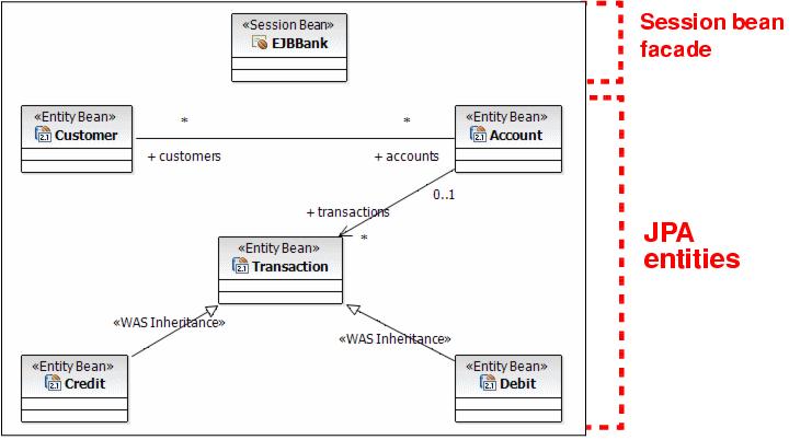
Figure | 4-6 shows the sample application model layer design.

Figure 14-6 EJB module class diagram for the sample application
The EJBBank session bean acts as a facade for the EJB model. The business entities (Customer, Account, Transaction, Credit, and Debit) are implemented as CMP entity beans with local interfaces, as opposed to regular JavaBeans.
By doing so, we automatically gain persistence, security, distribution, and transaction management services. On the other hand, this also implies that the control and view layers are not able to reference these entities directly, because they can be placed in a different JVM. Only the session bean (EJBBank) can access the business entities through their local interfaces.
You might be asking yourself, then, why we do not expose a remote interface for the entity beans as well? The problem with doing that is two-fold. First, in such a design, clients would probably make many remote calls to the model to resolve each client request. This is not a recommended practice because remote calls are more expensive than local ones. Finally, allowing clients to see into the model breaks the layer's encapsulation, promoting unwanted dependencies and coupling.
Because the control layer is not able to reference the model objects directly,
we reuse the Customer, Account, Transaction, Credit, and Debit from the Java application in Chapter | , Developing Java applications as data transfer objects, carrying data to the servlets and JSPs, but allowing no direct access to the underlying model.
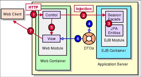
Figure | 4-7 shows the application component model and the flow of events.

Figure 14-7 Application component model and workflow
The flow of events, as shown in Figure | 4-7, is as follows:
| 1. | The first event that occurs is the HTTP request issued by the Web client to the server. This request is answered by a servlet in the control layer, also known as the front controller, which extracts the parameters from the request. The servlet sends the request to the appropriate control JavaBean. This bean verifies whether the request is valid in the current user and application states. |
| 2. | If so, the control layer sends the request through the @EJB injected interface to the session EJB facade. This involves using JNDI to locate the session bean's interface and creating a new instance of the bean. |
| 3. | The session EJB executes the appropriate business logic related to the request. This includes accessing JPA entities in the model layer. |
| 4. | The facade returns DTOs to the calling controller servlet with the response data. The DTO returned can be a JPA entity, a collection of JPA entities, or any Java object. In general, it is not necessary to create extra DTOs for entity data. |
| 5. | The front controller servlet sets the response DTO as a request attribute and forwards the request to the appropriate JSP in the view layer, responsible for rendering the response back to the client. |
| 6. | The view JSP accesses the response DTO to build the user response. |
| 7. | The result view, possibly in HTML, is returned to the client. |
|
ibm.com/redbooks |