Modeling with diagrams
You can use data diagrams to visualize and edit objects that are contained in data projects. Data diagrams are a view representation of an underlying data model. You can create diagrams that contain only a subset of model objects that are of interest.
In this section, we create a schema named RAD75Bank in the physical data model. Under this schema, we create two tables: ACCOUNT and TRANSACT. we add a foreign key relationship between the ACCOUNT and TRANSACT tables.

| In the Data Project Explorer select RAD75DataDesign Æ Data Models Æ Bank_model.dbm Æ Database Æ Schema, and in the Properties view change the schema name from Schema to RAD75Bank. |

| To add a table, do these steps: |

 In the diagram editor, select the Data drawer in the palette and select Table in the Data drawer.
|

 Click the empty area in the data diagram. A new table is added to the diagram.
|

 Overtype the table name with ACCOUNT.
|

| Hover the mouse over the ACCOUNT table in the diagram and you see four icons appearing outside of the table (Figure | 1-31). Click the Add Key icon. |

Figure 11-31 Add key, column, index, and trigger

| Overtype the name with ID (or change the name in the Properties view, General tab). |

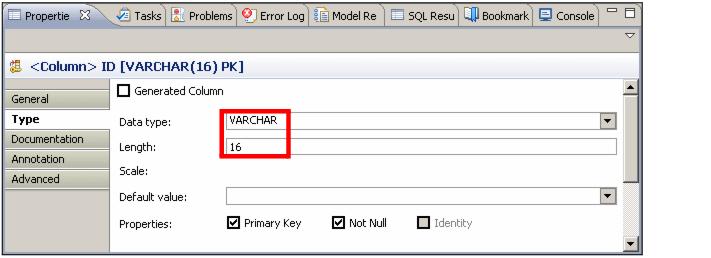
| Select the ID column, and in the Properties view, Type tab, change the Data type to VARCHAR. Set the Length to 16 (Figure | 1-32). |

Figure 11-32 Edit the key
|
Note: The key ID must be uppercase. If you use lowercase, you might get the following error message when you run DDL on server in later section: SQL Exception: 'ID' is not a column in table or VTI 'ACCOUNT'.. |

| Hover the mouse over the ACCOUNT table and click the Add Column icon. |

| In the Properties view change the Name to BALANCE, the data type to DECIMAL, enter 8 as the precision and 2 as the scale, and select Not Null. |

| Follow the same procedure to create the TRANSACT table: |

 Key: ID VARCHAR(250) NOT NULL
|

 Columns:
|
TRANS_TYPE VARCHAR(32) NOT NULL
TRANS_TIME TIMESTAMP NOT NULL
AMOUNT DECIMAL(8,2) NOT NULL
ACCOUNT_ID VARCHAR(16)

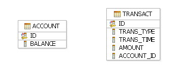
| The data diagram is shown in Figure | 1-33. |

Figure 11-33 Data diagram with two tables

| Hover the mouse over the ACCOUNT table object in the diagram and you should see two arrows appearing outside of the table, pointing in opposite directions. |
Use the arrow that points away from the ACCOUNT table (representing a relationship from parent to child) to create a relationship between the ACCOUNT table and the TRANSACT table.

| Drag the arrow that points away from the ACCOUNT table, and drop it on the TRANSACT table. In the menu that opens select Create Non-Identifying Optional FK Relationship (Figure | 1-34) |

Figure 11-34 Add relationship between tables

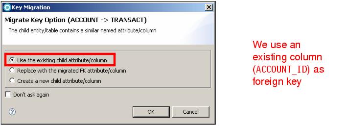
| In the Migrate Key Option dialog, select Use the existing child attribute/column, and click OK (Figure | 1-35). |

Figure 11-35 Key migration

| Select the foreign key relationship that you just created. In the Properties view, select the Details page. |

| Click the ellipsis button  next to the Key Columns field. In the dialog, that opens, select ACCOUNT_ID and clear ID (use the check boxes). Click OK. next to the Key Columns field. In the dialog, that opens, select ACCOUNT_ID and clear ID (use the check boxes). Click OK.
|

| Add information to the relationship properties to identify the roles of each table in the relationship (Figure | 1-36): |

 In the Inverse Verb Phrase field, type transaction.
|

 In the Verb Phrase field, type account.
|

 Leave the cardinality as * and 0..1.
|

Figure 11-36 Relationship Details page

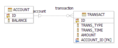
| Save but do not close the diagram. Notice the relationship verbs account and transaction in the diagram (Figure | 1-37). |

Figure 11-37 Relationship with verbs
|
ibm.com/redbooks |