Browse diagrams
A browse diagram is a structural diagram that provides a view of a context element such as a class, a package, or an EJB. It is a temporary read-only diagram that provides the capability to explore the given context element. You can view the element details, including attributes, methods, and relationships to other elements, and you are able to navigate to those elements. Browse diagrams can be applied to various elements including Java classes and Enterprise JavaBeans, but excluded are all elements related to Web services.
You can create a browse diagram from any source element or its representation within a class diagram. To create a browse diagram, right-click the desired element and select Visualize Æ Explore in Browse Diagram. A browse diagram is created and shown in the corresponding diagram editor. The diagram editor consists of a panel displaying the selected element along with its relationships and a tool bar. Because a browse diagram is not editable, the palette and the modeling assistant are not available. Depending on the elements shown, the diagram is displayed either using the radial or generalization tree layout type. The radial layout type shows the selected element in the center of the diagram, whereas the generalization tree layout type organizes the general classes at the top of the diagram and the subclasses at the bottom.
The browse diagram acts like a Web browser for your code. It provides a history and navigation, and you can customize the UML relationships you want to see. The tool bar located at the top of the browse diagram displays the context element you are currently browsing. At any one time, there is only one browse diagram open. When you browse another element, it is displayed in the same diagram replacing the previous element.
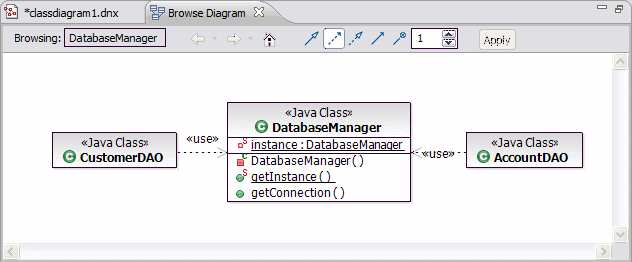
Figure | -30 shows an example browse diagram with the Java class DatabaseManager as the context element. You can see all the attributes and methods declared by this class. In this case, the dependency filter button is the only one highlighted, and so elements involved in a dependency relationship with DatabaseManager are shown as well. You can see that AccountDAO and CustomerDAO both depend on DatabaseManager.

Figure 7-30 Browse diagram example
The browse diagram retains the history of elements you have viewed so far. You can use the two arrow buttons provided in the tool bar to navigate backward or forward to browse previously viewed elements.
When you click the Home icon  , the first element in the history is displayed. Furthermore, the tool bar contains a list of filter icons that can be used to filter the types of relationships that are shown along with the context element. Note that there are different filters available depending on the type of element you are currently browsing for example Java class or EJB. To enable or disable a filter, click the appropriate icon and then click Apply.
You can also change the number of levels of relationships that are shown for the context element. The default value is one. To change this value, specify a number and click Apply.
In Figure | -30 the Home icon and the two arrow icons are disabled, so the current element is the first element in the browse diagram history.
To explore the details of a diagram element, double-click it. This element becomes the new context element. When you right-click a diagram element, the Navigate submenu provides several options such as opening the Java source of a diagram element.
A browse diagram cannot be changed or saved, but Rational Application Developer lets you save any browse diagram view as a diagram file that is fully editable. Right-click an empty space inside a browse diagram and select
File Æ Save as Diagram File. To use a browse diagram as part of permanent documentation, you can save a browse diagram view as an image file using File Æ Save as Image File.
|
ibm.com/redbooks |