WAS configuration
Now that the underlying messaging system has been constructed, the components within WAS can be put together to provide the complete platform for Trade3 to run on.
Note Before setting up any infrastructure, the Trade3 application needs to be altered to use durable instead of non-durable subscriptions. Open up the EAR file using WebSphere Studio Application Developer or the Application Server toolkit and edit the EJB deployment descriptor. On the Beans panel, change the subscription of the TradeStreamerMDB to durable. Save the file then export the new EAR file. |
There are four appservers that are going to be deployed. Each of them uses the messaging system in a slightly different way to reduce single points of failure in the topology. This means effective use of the scope setting for each QCF, TCF, queue and topic. Whilst running through these steps keep in mind the overall picture as this is a complicated configuration. Figure 15-24 shows what JMS provider objects need to be configured to get this topology to work.

Figure 15-24 Usage of JMS provider objects in sample topology
Setup Trade3 cluster part 1
In the first example it was possible to use the scripts that come with Trade3.1 to do a lot of the work. Unfortunately the scripts will not assist this time around so the creation of the cluster will be done in two stages, creating the cluster and the first server, then adding new cluster members later on. The advantage of this is that all resources defined at server scope will be copied over to the new servers.
Configure JDBC resources
Trade3 needs access to a database to work. There is a script that comes with the Trade3.1 package that will setup the necessary JDBC resources, it is called createTrade3RDBMSResources.jacl. Its syntax is:
wsadmin -f createTrade3RDBMSResources.jacl dbtype <-cell | nodeName>
rdbmsDriverClassPath rdbmsUser rdbmsPassword \[oracledbhost\] \[oraclesid\]
In this example there are two nodes. On each node the location of DB2 driver classes is exactly the same, so to save on configuration the JDBC resources can be created at cell level. For this environment it was done using the command:
wsadmin -f t3installl\createTrade3RDBMSResources.jacl db2 -cell
c:/progra~1/sqllib/java/db2java.zip db2admin db2admin
To complete the setup of the database access, the Trade database needs to be catalogued locally on each of the clients. Refer to 7.7, Installing and configuring Trade3.1 for details on how to do this.
Configure JMS resources part 1
The first task is to identify how many JMS components need defining within the cell.
By looking at Figure 15-16 it is possible to see that for point-to-point messaging each of the appservers need to access the WebSphere MQ cluster in a different way. This is because each possible combination of two queue managers and two forms of communication needs to be covered (CLIENT and BINDINGS). This is achieved by creating all the relevant QCF objects at the server scope, making them visible only to that server.
For publish/subscribe messaging, the MDB has a durable subscription. Each appserver needs to receive a copy of any published message so TCFs cannot be shared. Four application servers means there needs to be four durable subscriptions, each made unique by the client ID set on the TCF. (as the MDB name is the same - cloned application). This means defining the TCF objects at the server scope level as well. More information on this can be found in Client ID and Enable Clone support on a TCF.
Finally the queue destination and topic destination contain no information that is specific to a particular appserver, so these can be configured at cell level.
Follow these steps to create the necessary listener ports and JMS provider objects on Trade3Server1.
After completing these steps, Trade3Server1 will be used as a template to create the other servers and the final changes will be made. This will include configuring dedicated QCFs and TCFs for the listener ports to use. As discussed in Use separate QCF and TCF for MDBs this allows for specific configuration of a QCF or TCF for listener port usage and makes defining the size of the connection and session pools simpler.
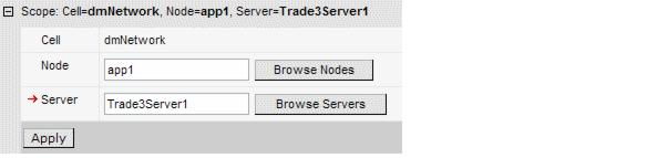
Figure 15-25 Set the scope level to app1, Trade3Server1
Table 15-5 TradeBrokerQCF
| Field | Value |
|---|---|
| Name | TradeBrokerQCF |
| JNDI Name | jms/TradeBrokerQCF |
| Queue Manager | TRADEQM1 |
| Transport Type | BINDINGS |
| Component-managed Authentication Alias | TradeDataSourceAuthData |
| Container-managed Authentication Alias | TradeDataSourceAuthData |
| Enable XA | True |
Table 15-6 TradeBrokerListenerPortQCF
| Field | Value |
|---|---|
| Name | TradeBrokerListenerPortQCF |
| JNDI Name | jms/TradeBrokerLPQCF |
| Queue Manager | TRADEQM1 |
| Transport Type | BINDINGS |
| Component-managed Authentication Alias | TradeDataSourceAuthData |
| Container-managed Authentication Alias | TradeDataSourceAuthData |
| Enable XA | True |
Table 15-7
| Field | Value |
| Name | TradeStreamerListenerPortTCF |
| JNDI Name | jms/TradeStreamerLPTCF |
| Transport Type | BINDINGS |
| Component-managed Authentication Alias | TradeDataSourceAuthData |
| Container-managed Authentication Alias | TradeDataSourceAuthData |
| Queue Manager | TRADEQM1 |
| Broker Queue Manager | WBRK_QM |
| Broker Publication Queue | SOCCER_PUBLICATION (Name of the queue that was setup on WBRK_QM. It is being monitored by the broker based on the sample message flow). |
| Broker Subscription Queue | SOCCER_SUBSCRIPTION |
| Broker Version | Advanced |
| Enable clone support | Uncheck (False). Although there is use of durable subscriptions, this TCF is only being used by one appserver in the cluster and so there is no issue with MDB listener ports starting up with the same client IDs. |
| Client ID | Trade3Server1. This unique ID is what allows multiple durable subscriptions on the same topic from with in the server cluster. This needs to be different for each server scope. |
| Enable XA | Uncheck (False). There is no requirement for 2PC on this object. |
TradeStreamerListenerPortTCF
Table 15-8
| Field | Value |
| Name | TradeStreamerTCF |
| JNDI Name | jms/TradeStreamerTCF |
| Transport Type | BINDINGS |
| Component-managed Authentication Alias | TradeDataSourceAuthData |
| Container-managed Authentication Alias | TradeDataSourceAuthData |
| Queue Manager | TRADEQM1 |
| Broker Queue Manager | WBRK_QM |
| Broker Publication Queue | SOCCER_PUBLICATION |
| Broker Subscription Queue | SOCCER_SUBSCRIPTION |
| Broker Version | Advanced |
| Enable clone support | Uncheck (False) |
| Client ID | Trade3Server1 |
| Enable XA | Uncheck (False). There is no requirement for 2PC on this object. |
TradeStreamerTCF
Table 15-9
| Field | Value |
| Name | TradeBrokerQueue |
| JNDI Name | jms/TradeBrokerQueue |
| Persistence | PERSISTENT |
| Base Queue Name | TRADE_MAINFRAME |
TradeBrokerQueue
Table 15-10
| Field | Value |
| Name | TradeBrokerResponseQueue |
| JNDI Name | jms/TradeBrokerResponseQueue |
| Persistence | PERSISTENT |
| Base Queue Name | TRADE3_RESPONSE |
TradeBrokerResponseQueue
Table 15-11
| Field | Value |
| Name | TradeStreamerTopic |
| JNDI Name | jms/TradeStreamerTopic |
| Persistence | PERSISTENT |
| Topic | TradeStreamerTopic |
TradeStreamerTopic
Table 15-12
| Field | Value |
| Name | tradeport |
| Connection factory JNDI Name | jms/TradeBrokerLPQCF |
| Destination JNDI Name | jms/TradeBrokerResponseQueue |
| Maximum Sessions | 5 |
| Maximum Retries | 10 |
tradeport
Table 15-13
| Field | Value |
| Name | tradetopicport |
| Connection factory JNDI Name | jms/TradeStreamerLPTCF |
| Destination JNDI Name | jms/TradeStreamerTopic |
| Maximum Sessions | 1 |
| Maximum Retries | 10 |
tradetopicport
Setup Trade3 cluster part 2
It is now time to create the other three servers. Trade3Server1 will now be used as a template, reducing the effort to setup all the JMS resources.
Configure JMS resources part 2
The final step in this setup is to change the QCFs and TCFs for Trade3Server2, 3 and 4 to point to the correct queue manager using the correct transport type. As Trade3Server1 was used as a template for creating these new appservers, all of its resources have come across as well. The listener ports do not need changing. All that needs changing are the QCF and TCF objects.
Table 15-14 TradeBrokerQCF
| Field | Value |
|---|---|
| Name | TradeBrokerQCF |
| Queue Manager | TRADEQM2 |
| Transport Type | CLIENT |
Table 15-15 TradeBrokerListenerPortQCF
| Field | Value |
|---|---|
| Name | TradeBrokerListenerPortQCF |
| Queue Manager | TRADEQM2 |
| Transport Type | CLIENT |
Table 15-16 TradeStreamerTCF
| Field | Value |
|---|---|
| Name | TradeStreamerTCF |
| Client ID | Trade3Server2 |
Table 15-17 TradeStreamerListenPortTCF
| Field | Value |
|---|---|
| Name | TradeStreamerListenerPortTCF |
| Client ID | Trade3Server2 |
Table 15-18 TradeBrokerQCF
| Field | Value |
|---|---|
| Name | TradeBrokerQCF |
| Queue Manager | TRADEQM1 |
| Transport Type | CLIENT |
Table 15-19 TradeBrokerListenerPortQCF
| Field | Value |
|---|---|
| Name | TradeBrokerListenerPortQCF |
| Queue Manager | TRADEQM1 |
| Transport Type | CLIENT |
Table 15-20 TradeStreamerTCF
| Field | Value |
|---|---|
| Name | TradeStreamerTCF |
| Queue Manager | TRADEQM2 |
| Client ID | Trade3Server3 |
Table 15-21 TradeStreamerListenerPortTCF
| Field | Value |
|---|---|
| Name | TradeStreamerListenerPortTCF |
| Queue Manager | TRADEQM2 |
| Client ID | Trade3Server3 |
Table 15-22 TradeBrokerQCF
| Field | Value |
|---|---|
| Name | TradeBrokerQCF |
| Queue Manager | TRADEQM2 |
| Transport Type | BINDINGS |
Table 15-23 TradeBrokerListenerPortQCF
| Field | Value |
|---|---|
| Name | TradeBrokerListenerPortQCF |
| Queue Manager | TRADEQM2 |
| Transport Type | BINDINGS |
Table 15-24 TradeStreamerTCF
| Field | Value |
|---|---|
| Name | TradeStreamerTCF |
| Queue Manager | TRADEQM2 |
| Client ID | Trade3Server4 |
Table 15-25 TradeStreamerListenerPortTCF
| Field | Value |
|---|---|
| Name | TradeStreamerListenerPortTCF |
| Queue Manager | TRADEQM2 |
| Client ID | Trade3Server4 |
Install the application
Use the WebSphere Administrative Console to install the Trade3.ear file. Accept all defaults. The Trade3.ear file is already configured to use the correct JNDI names and listener ports for this example. The fact that we created extra QCFs and TCFs for the listener ports, and where those QCFs and TCFs point, is masked from the application itself.
The application is now installed in your cluster and ready to run.
Testing the application
The queue managers and message brokers should already be started. If you receive any errors when starting up the appservers verify that the WebSphere MQ cluster is working by looking at the channel and listener status in the WebSphere MQ Explorer. Also, don't forget to start the TradeRedirector application to do the back-end processing.
The Trade3 application will default to using Synchronous as the order process mechanism on each server. For this reason change the Trade3 configuration on each of the servers. For each server go to
http://<appX>:9080/trade/config
and change the following configuration parameters:
| Order processing mode = Asynchronous_1-Phase |
| Enable Operational Trace = True |
| Enable Full Trace = True |
Press Update config to complete.
Trade3 will now be up and running. There are many aspects of the failover to try out. Here are a couple of tests to start off with:
WebSphere is a trademark of the IBM Corporation in the United States, other countries, or both.
IBM is a trademark of the IBM Corporation in the United States, other countries, or both.