Using Clusters
Failover and Replication in a Cluster
In order for a cluster to provide high availability it must be able to recover from service failures. The following sections describe how WebLogic Server detects failures in a cluster, and provides an overview of how failover is accomplished for different types of objects:
- How WebLogic Server Detects Failures
- Replication and Failover for Servlets and JSPs
- Replication and Failover for EJBs and RMIs
- Failover and JDBC Connections
This chapter focuses on failover and replication at the application level. WebLogic Server also supports automatic migration of server instances and services after failure. For more information, see Whole Server Migration.
How WebLogic Server Detects Failures
WebLogic Server instances in a cluster detect failures of their peer server instances by monitoring:
- Socket connections to a peer server
- Regular server heartbeat messages
Failure Detection Using IP Sockets
WebLogic Server instances monitor the use of IP sockets between peer server instances as an immediate method of detecting failures. If a server connects to one of its peers in a cluster and begins transmitting data over a socket, an unexpected closure of that socket causes the peer server to be marked as “failed,” and its associated services are removed from the JNDI naming tree.
The WebLogic Server “Heartbeat”
If clustered server instances do not have opened sockets for peer-to-peer communication, failed servers may also be detected via the WebLogic Server heartbeat. All server instances in a cluster use multicast or unicast to broadcast regular server heartbeat messages to other members of the cluster.
For backward compatibility with previous versions, WebLogic Server also allows you to use multicast for communications between clusters.
Each heartbeat message contains data that uniquely identifies the server that sends the message. Servers broadcast their heartbeat messages at regular intervals of 10 seconds. In turn, each server in a cluster monitors the multicast or unicast address to ensure that all peer servers' heartbeat messages are being sent.
For backward compatibility with previous versions, WebLogic Server also allows you to use multicast for communications between clusters.
If a server monitoring the multicast or unicast address misses three heartbeats from a peer server (i.e., if it does not receive a heartbeat from the server for 30 seconds or longer), the monitoring server marks the peer server as “failed.” It then updates its local JNDI tree, if necessary, to retract the services that were hosted on the failed server.
In this way, servers can detect failures even if they have no sockets open for peer-to-peer communication.
For more information about how WebLogic Server uses IP sockets and either multicast or unicast communications see WebLogic Server Communication In a Cluster.
Replication and Failover for Servlets and JSPs
To support automatic replication and failover for servlets and JSPs within a cluster, Weblogic Server supports two mechanisms for preserving HTTP session state:
- Hardware load balancers
For clusters that use a supported hardware load balancing solution, the load balancing hardware simply redirects client requests to any available server in the WebLogic Server cluster. The cluster itself obtains the replica of the client's HTTP session state from a secondary server in the cluster.
- proxy plug-ins
In clusters that utilize Web servers with WebLogic proxy plug-ins, the proxy plug-in handles failover transparently to the client. If a server fails, the plug-in locates the replicated HTTP session state on a secondary server and redirects the client's request accordingly.
This section covers the following topics:
- HTTP Session State Replication
- Accessing Clustered Servlets and JSPs Using a Proxy
- Accessing Clustered Servlets and JSPs with Load Balancing Hardware
- Session State Replication Across Clusters in a MAN/WAN
HTTP Session State Replication
Weblogic Server uses two methods for replicating HTTP session state across clusters:
- in-memory replication
Using in-memory replication, WebLogic Server copies a session state from one server instance to another. The primary server creates a primary session state on the server to which the client first connects, and a secondary replica on another WebLogic Server instance in the cluster. The replica is kept up-to-date so that it may be used if the server that hosts the servlet fails.
- JDBC-based persistence
In JDBC-based persistence, WebLogic Server maintains the HTTP session state of a servlet or JSP using file-based or JDBC-based persistence. For more information on these persistence mechanisms, see “Configuring Session Persistence” in Developing Web Applications, Servlets, and JSPs for Oracle WebLogic Server.
JDBC-based persistence is also used for HTTP session state replication within a Wide Area Network (WAN). For more information, see WAN HTTP Session State Replication.
WebApps which have persistent store type set to replicated or replicated_if_clustered will have to be targeted to the cluster or all the nodes of that cluster. If its targeted to only some nodes in the cluster then the webapp will not be deployed. In memory replication requires that webapps be deployed homogeneously on all the nodes in a cluster.
The following section describe session state replication using in-memory replication.
Requirements for HTTP Session State Replication
To utilize in-memory replication for HTTP session states, access the WebLogic Server cluster using either a collection of Web servers with identically configured WebLogic proxy plug-ins, or load balancing hardware.
Supported Server and Proxy Software
The WebLogic proxy plug-in maintains a list of WebLogic Server instances that host a clustered servlet or JSP, and forwards HTTP requests to those instances using a round-robin strategy. The plug-in also provides the logic necessary to locate the replica of a client's HTTP session state if a WebLogic Server instance should fail.
In-memory replication for HTTP session states is supported by the following Web servers and proxy software:
- WebLogic Server with the HttpClusterServlet
- Apache with the Apache Server (proxy) plug-in
- Microsoft Internet Information Server with the Microsoft-IIS (proxy) plug-in
For instructions on setting up proxy plug-ins, see Configure Proxy Plug-Ins.
Load Balancer Requirements
If you choose to use load balancing hardware instead of a proxy plug-in, it must support a compatible passive or active cookie persistence mechanism, and SSL persistence. For details on these requirements, see Load Balancer Configuration Requirements. For instructions on setting up a load balancer, see Configuring Load Balancers that Support Passive Cookie Persistence.
Programming Considerations for Clustered Servlets and JSPs
This section highlights key programming constraints and recommendations for servlets and JSPs that you will deploy in a clustered environment.
- Session Data Must Be Serializable
To support in-memory replication of HTTP session states, all servlet and JSP session data must be serializable.
Serialization is the process of converting a complex data structure, such as a parallel arrangement of data (in which a number of bits are transmitted at a time along parallel channels) into a serial form (in which one bit at a time is transmitted); a serial interface provides this conversion to enable data transmission.
Every field in an object must be serializable or transient in order for the object to be considered serializable. If the servlet or JSP uses a combination of serializable and non-serializable objects, WebLogic Server does not replicate the session state of the non-serializable objects.
- Use setAttribute to Change Session State
In an HTTP servlet that implements javax.servlet.http.HttpSession, use HttpSession.setAttribute (which replaces the deprecated putValue) to change attributes in a session object. If you set attributes in a session object with setAttribute, the object and its attributes are replicated in a cluster using in-memory replication. If you use other set methods to change objects within a session, WebLogic Server does not replicate those changes. Every time a change is made to an object that is in the session, setAttribute() should be called to update that object across the cluster.
Likewise, use removeAttribute (which, in turn, replaces the deprecated removeValue) to remove an attribute from a session object.
Use of the deprecated putValue and removeValue methods will also cause session attributes to be replicated.
- Consider Serialization Overhead
Serializing session data introduces some overhead for replicating the session state. The overhead increases as the size of serialized objects grows. If you plan to create very large objects in the session, test the performance of your servlets to ensure that performance is acceptable.
- Control Frame Access to Session Data
If you are designing a Web application that utilizes multiple frames, keep in mind that there is no synchronization of requests made by frames in a given frameset. For example, it is possible for multiple frames in a frameset to create multiple sessions on behalf of the client application, even though the client should logically create only a single session.
In a clustered environment, poor coordination of frame requests can cause unexpected application behavior. For example, multiple frame requests can “reset” the application's association with a clustered instance, because the proxy plug-in treats each request independently. It is also possible for an application to corrupt session data by modifying the same session attribute via multiple frames in a frameset.
To avoid unexpected application behavior, carefully plan how you access session data with frames. You can apply one of the following general rules to avoid common problems:
- In a given frameset, ensure that only one frame creates and modifies session data.
- Always create the session in a frame of the first frameset your application uses (for example, create the session in the first HTML page that is visited). After the session has been created, access the session data only in framesets other than the first frameset.
Using Replication Groups
By default, WebLogic Server attempts to create session state replicas on a different machine than the one that hosts the primary session state. You can further control where secondary states are placed using replication groups. A replication group is a preferred list of clustered servers to be used for storing session state replicas.
Using the WebLogic Server Console, you can define unique machine names that will host individual server instances. These machine names can be associated with new WebLogic Server instances to identify where the servers reside in your system.
Machine names are generally used to indicate servers that run on the same machine. For example, you would assign the same machine name to all server instances that run on the same machine, or the same server hardware.
If you do not run multiple WebLogic Server instances on a single machine, you do not need to specify WebLogic Server machine names. Servers without a machine name are treated as though they reside on separate machines. For detailed instructions on setting machine names, see Configure Machine Names.
When you configure a clustered server instance, you can assign the server to a replication group, and a preferred secondary replication group for hosting replicas of the primary HTTP session states created on the server.
When a client attaches to a server in the cluster and creates a primary session state, the server hosting the primary state ranks other servers in the cluster to determine which server should host the secondary. Server ranks are assigned using a combination of the server's location (whether or not it resides on the same machine as the primary server) and its participation in the primary server's preferred replication group. The following table shows the relative ranking of servers in a cluster.
| Server Rank | Server Resides on a Different Machine | Server is a Member of Preferred Replication Group |
|---|---|---|
| 1 | Yes | Yes |
| 2 | No | Yes |
| 3 | Yes | No |
| 4 | No | No |
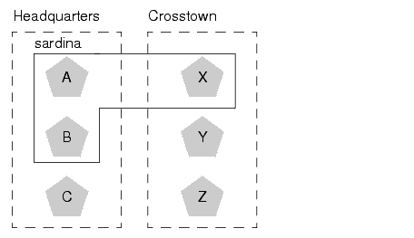
Using these rules, the primary WebLogic Server ranks other members of the cluster and chooses the highest-ranked server to host the secondary session state. For example, the following figure shows replication groups configured for different geographic locations. Figure 6-1 Replication Groups for Different Geographic Locations
In this example, Servers A, B, and C are members of the replication group “Headquarters” and use the preferred secondary replication group “Crosstown.” Conversely, Servers X, Y, and Z are members of the “Crosstown” group and use the preferred secondary replication group “Headquarters.” Servers A, B, and X reside on the same machine, “sardina.”
If a client connects to Server A and creates an HTTP session state,
- Servers Y and Z are most likely to host the replica of this state, since they reside on separate machines and are members of Server A's preferred secondary group.
- Server X holds the next-highest ranking because it is also a member of the preferred replication group (even though it resides on the same machine as the primary.)
- Server C holds the third-highest ranking since it resides on a separate machine but is not a member of the preferred secondary group.
- Server B holds the lowest ranking, because it resides on the same machine as Server A (and could potentially fail along with A if there is a hardware failure) and it is not a member of the preferred secondary group.
To configure a server's membership in a replication group, or to assign a server's preferred secondary replication group, follow the instructions in Configure Replication Groups.
Accessing Clustered Servlets and JSPs Using a Proxy
This section describes the connection and failover processes for requests that are proxied to clustered servlets and JSPs. For instructions on setting up proxy plug-ins, see Configure Proxy Plug-Ins.
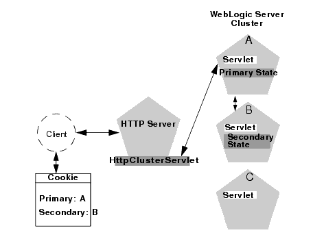
The following figure depicts a client accessing a servlet hosted in a cluster. This example uses a single WebLogic Server to serve static HTTP requests only; all servlet requests are forwarded to the WebLogic Server cluster via the HttpClusterServlet. Figure 6-2 Accessing Servlets and JSPs using a Proxy
The discussion that follows also applies if you use a third-party Web server and WebLogic proxy plug-in, rather than WebLogic Server and the HttpClusterServlet.
Proxy Connection Procedure
When the HTTP client requests the servlet, HttpClusterServlet proxies the request to the WebLogic Server cluster. HttpClusterServlet maintains the list of all servers in the cluster, and the load balancing logic to use when accessing the cluster. In the above example, HttpClusterServlet routes the client request to the servlet hosted on WebLogic Server A. WebLogic Server A becomes the primary server hosting the client's servlet session.
To provide failover services for the servlet, the primary server replicates the client's servlet session state to a secondary WebLogic Server in the cluster. This ensures that a replica of the session state exists even if the primary server fails (for example, due to a network failure). In the example above, Server B is selected as the secondary.
The servlet page is returned to the client through the HttpClusterServlet, and the client browser is instructed to write a cookie that lists the primary and secondary locations of the servlet session state. If the client browser does not support cookies, WebLogic Server can use URL rewriting instead.
Using URL Rewriting to Track Session Replicas
In its default configuration, WebLogic Server uses client-side cookies to keep track of the primary and secondary server that host the client's servlet session state. If client browsers have disabled cookie usage, WebLogic Server can also keep track of primary and secondary servers using URL rewriting. With URL rewriting, both locations of the client session state are embedded into the URLs passed between the client and proxy server. To support this feature, ensure that URL rewriting is enabled on the WebLogic Server cluster. For instructions on how to enable URL rewriting, see “Using URL Rewriting Instead of Cookies” in Developing Web Applications, Servlets, and JSPs for Oracle WebLogic Server.
Proxy Failover Procedure
Should the primary server fail, HttpClusterServlet uses the client's cookie information to determine the location of the secondary WebLogic Server that hosts the replica of the session state. HttpClusterServlet automatically redirects the client's next HTTP request to the secondary server, and failover is transparent to the client.
After the failure, WebLogic Server B becomes the primary server hosting the servlet session state, and a new secondary is created (Server C in the previous example). In the HTTP response, the proxy updates the client's cookie to reflect the new primary and secondary servers, to account for the possibility of subsequent failovers.
In a two-server cluster, the client would transparently fail over to the server hosting the secondary session state. However, replication of the client's session state would not continue unless another WebLogic Server became available and joined the cluster. For example, if the original primary server was restarted or reconnected to the network, it would be used to host the secondary session state.
Accessing Clustered Servlets and JSPs with Load Balancing Hardware
To support direct client access via load balancing hardware, the WebLogic Server replication system allows clients to use secondary session states regardless of the server to which the client fails over. WebLogic Server uses client-side cookies or URL rewriting to record primary and secondary server locations. However, this information is used only as a history of the servlet session state location; when accessing a cluster via load balancing hardware, clients do not use the cookie information to actively locate a server after a failure.
The following sections describe the connection and failover procedure when using HTTP session state replication with load balancing hardware.
Connection with Load Balancing Hardware
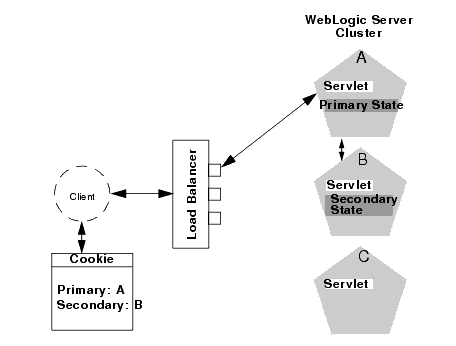
The following figure illustrates the connection procedure for a client accessing a cluster through a load balancer. Figure 6-3 Connection with Load Balancing Hardware
When the client of a Web application requests a servlet using a public IP address:
- The load balancer routes the client's connection request to a WebLogic Server cluster in accordance with its configured policies. It directs the request to WebLogic Server A.
- WebLogic Server A acts as the primary host of the client's servlet session state. It uses the ranking system described in Using Replication Groups to select a server to host the replica of the session state. In the example above, WebLogic Server B is selected to host the replica.
- The client is instructed to record the location of WebLogic Server instances A and B in a local cookie. If the client does not allow cookies, the record of the primary and secondary servers can be recorded in the URL returned to the client via URL rewriting.
You must enable WebLogic Server URL rewriting capabilities to support clients that disallow cookies, as described in Using URL Rewriting to Track Session Replicas.
- As the client makes additional requests to the cluster, the load balancer uses an identifier in the client-side cookie to ensure that those requests continue to go to WebLogic Server A (rather than being load-balanced to another server in the cluster). This ensures that the client remains associated with the server hosting the primary session object for the life of the session.
Failover with Load Balancing Hardware
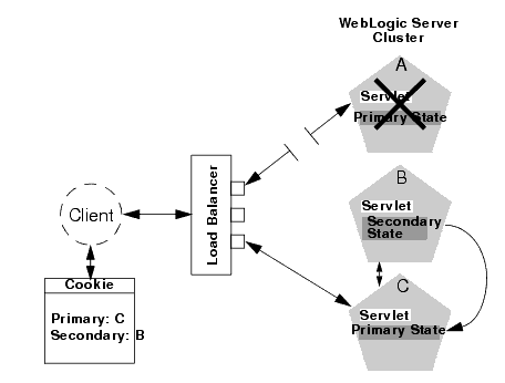
Should Server A fail during the course of the client's session, the client's next connection request to Server A also fails, as illustrated in the following figure. Figure 6-4 Failover with Load Balancing Hardware
In response to the connection failure:
- The load balancing hardware uses its configured policies to direct the request to an available WebLogic Server in the cluster. In the above example, assume that the load balancer routes the client's request to WebLogic Server C after WebLogic Server A fails.
- When the client connects to WebLogic Server C, the server uses the information in the client's cookie (or the information in the HTTP request if URL rewriting is used) to acquire the session state replica on WebLogic Server B. The failover process remains completely transparent to the client.
WebLogic Server C becomes the new host for the client's primary session state, and WebLogic Server B continues to host the session state replica. This new information about the primary and secondary host is again updated in the client's cookie, or via URL rewriting.
Session State Replication Across Clusters in a MAN/WAN
In addition to providing HTTP session state replication across servers within a cluster, WebLogic server provides the ability to replicate HTTP session state across multiple clusters. This improves high-availability and fault tolerance by allowing clusters to be spread across multiple geographic regions, power grids, and internet service providers. This section discusses the two mechanisms for cross-cluster replication supported by WebLogic Server:
- Network Requirements for Cross-cluster Replication
- Configuration Requirements for Cross-Cluster Replication
- MAN HTTP Session State Replication
- WAN HTTP Session State Replication
For general information on HTTP session state replication, see HTTP Session State Replication. For more information on using hardware load balancers, see Accessing Clustered Servlets and JSPs with Load Balancing Hardware.
Network Requirements for Cross-cluster Replication
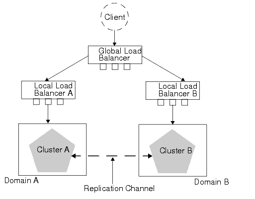
To perform cross-cluster replication with WebLogic Server, your network must include global and local hardware load balancers. Figure 6-5 shows how both types of load balancers interact within a multi-cluster environment to support cross-cluster replication. For general information on using load balancer within a WebLogic Server environment, see Connection with Load Balancing Hardware. Figure 6-5 Load Balancer Requirements for Cross-cluster Replications
The following sections describe each of the components in this network configuration.
Global Load Balancer
In a network configuration that supports cross-cluster replication, the global load balancer is responsible for balancing HTTP requests across clusters. When a request comes in, the global load balancer determines which cluster to send it to based on the current number of requests being handled by each cluster. Then the request is passed to the local load balancer for the chosen cluster.
Local Load Balancer
The local load balancer receives HTTP requests from the global load balancer. The local load balancer is responsible for balancing HTTP requests across servers within the cluster.
Replication
In order to replicate session data from one cluster to another, a replication channel must be configured to communicate session state information from the primary to the secondary cluster. The specific method used to replicate session information depends on which type of cross-cluster replication you are implementing. For more information, see MAN HTTP Session State Replication or WAN HTTP Session State Replication.
Failover
When a server within a cluster fails, the local load balancer is responsible for transferring the request to other servers within a cluster. When the entire cluster fails, the local load balancer returns HTTP requests back to the global load balancer. The global load balancer then redirects this request to the other local load balancer.
Configuration Requirements for Cross-Cluster Replication
The following procedures outline the basic steps required to configure cross-cluster replication.
- Install WebLogic server according to your network configuration and requirements. This includes installing a WebLogic Server instance on every physical machine that hosts a WLS instance.
- Install and configure the hardware load balancers. For more information on load balancer requirements see Network Requirements for Cross-cluster Replication. For more information on installing and configuring load balancers, see the documentation for your load balancer.
Following are some general considerations when configuring hardware load balancers to support cross-cluster replications:
- You must configure your load balancer to maintain session ids. If the load balancers do not maintain session id, subsequent requests will always be sent to a new server. For more information, see Connection with Load Balancing Hardware.
- You should ensure that the cluster failover timeout value is not set to high. This value should be around 3-5 seconds. Some hardware load balancers have default values that are much longer.
- You must configure your load balancer to know which backup cluster to use when a primary cluster or server fails.
- Create and configure your domains according to your cluster requirements.
Cross-cluster replication requires that each cluster be assigned to a different domain.
In addition to creating and configuring your domains, you should also create and configure your clusters and Managed Servers. For information about creating and configuring domains, clusters, and Managed Servers, see the following topics:
- “Understanding WebLogic Server Domains” in Understanding Domain Configuration
-
“Customizing the Environment” in Creating WebLogic Domains Using the Configuration Wizard
Following are some considerations when configuring domains to support cross-cluster replication:
- Each domain should be set up and configured identically. In addition to identical domain, cluster and server configuration, the number of servers clusters, etc. should be identical.
- Application deployment should be identical in each domain.
- When setting up your domains, enable trust between both domains. For more information on enabling trust between domains, see “Enabling Trust Between WebLogic Server Domains” in Securing WebLogic Server.
- If you are using cross cluster replication in a WAN environment, create a datasource that is used to maintain session state. For more information, see Database Configuration for WAN Session State Replication.
- After you have created and configured your domains, servers, and clusters you should verify the configuration elements specific to cross-cluster replication have been configured correctly. These parameters must be configured identically for both domains.
The following table lists the subelements of the cluster element in config.xml that are used to configure cross-cluster replication:
data-source-for-session-persistence This is the data source that is used to store session information when using JDBC-based session persistence. This method of session state replication is used to perform cross-cluster replication within a WAN. For more information, see Database Configuration for WAN Session State Replication. session-flush-interval This is the interval, in seconds, the cluster waits to flush HTTP sessions to the backup cluster. session-flush-threshold If the number of HTTP sessions reaches the value of session-flush-threshold, the sessions are flushed to the backup cluster. This allows servers to flush sessions faster under heavy loads. inter-cluster-comm-link-
health-check-intervalThis is the amount of time, in milliseconds, that the cluster waits to Configuring Session State Replication Across Clusters
You can use a third-party replication product to replicate state across clusters, or you can allow WebLogic Server to replicate session state across clusters. The following configuration considerations should be kept in mind depending on which method you use:
- If you are using a third-party product, ensure that you have specified a value for jdbc-pool, and that backup-cluster-address is blank.
- If you are using WebLogic Server to handle session state replication, configure both the jdbc-pool and the backup-cluster-address.
If backup-cluster-address is NULL, WebLogic Server assumes that you are using a third-party product to handle replication. In this case, session data is not persisted to the remote database, but is persisted locally.
Configuring a Replication Channel
A replication channel is a normal network channel that is dedicated specifically to replication traffic between clusters. For general information on configuring a network channel, see “Configuring Network Resources” in Configuring Server Environments.
When creating a network channel to be used as the replication channel in cross-cluster replication, the following considerations apply:
- You must ensure that the replication channel is created on all cluster members and has the same name.
- The channel should be used only for replication. Other types of network traffic should be directed to other network channels.
MAN HTTP Session State Replication
Resources within a metropolitan area network (MAN) are often in physically separate locations, but are geographically close enough that network latency is not an issue. Network communication in a MAN generally has low latency and fast interconnect. Clusters within a MAN can be installed in physically separate locations which improves availability.
To provide failover within a MAN, WebLogic Server provides an in-memory mechanism that works between two separate clusters. This allows session state to be replicated synchronously from one cluster to another, provided that the network latency is a few milliseconds. The advantage of using a synchronous method is that reliability of in-memory replication is guaranteed.
The performance of synchronous state replication is dependant on the network latency between clusters. You should use this method only if the network latency between the clusters is tolerable.
Replication Within a MAN
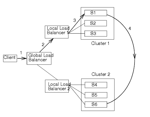
This section discusses possible failover scenarios across multiple clusters within a MAN. Figure 6-6, MAN Replication, on page 6-20 shows a typical multi-cluster environment within a MAN. Figure 6-6 MAN Replication
This figure shows the following HTTP session state scenario:
- A client makes a request which passes through the global load balancer.
- The global load balancer passes the request to a local load balancer based on current system load. In this case, the session request is passed to Local Load Balancer 1.
- The local load balancer in turn passes the request to a server within a cluster based on system load, in this case S1. Once the request reaches S1, this managed server becomes the primary server for this HTTP session. This server will handle subsequent requests assuming there are no failures.
- Session state information is stored in the database of the primary cluster.
- After the server establishes the HTTP session, the current session state is replicated to the designated secondary server.
Failover Scenarios in a MAN
The following sections describe various failover scenarios based on the MAN configuration in Figure 6-7, WAN Replication, on page 6-23.
Failover Scenario 1
If all of the servers in Cluster 1 fail, the global load balancer will automatically fail all subsequent session requests to Cluster 2. All sessions that have been replicated to Cluster 2 will be recovered and the client will experience no data loss.Failover Scenario 2
Assume that the primary server S1 is being hosted on Cluster 1, and the secondary server S6 is being hosted on Cluster 2. If S1 crashes, then any other server in Cluster 1 (S2 or S3) can pick up the request and retrieve the session data from server S6. S6 will continue to be the backup server.Failover Scenario 3
Assume that the primary server S1 is being hosted on Cluster 1, and the secondary server S6 is being hosted on Cluster 2. If the secondary server S6 fails, then the primary server S1 will automatically select a new secondary server on Cluster 2. Upon receiving a client request, the session information will be backed up on the new secondary server.Failover Scenario 4
If the communication between the two clusters fails, the primary server will automatically replicate session state to a new secondary server within the local cluster. Once the communication between the two clusters, any subsequent client requests will be replicated on the remote cluster.MAN Replication, Load Balancers, and Session Stickiness
MAN replication relies on global load balancers to maintain cluster affinity and local load balancers to maintain server affinity. If a server within a cluster fails, the local load balancer is responsible for ensuring that session state is replicated to another server in the cluster. If all of the servers within a cluster have failed or are unavailable, the global load balancer is responsible for replicating session state to another cluster. This ensures that failover to another cluster does not occur unless the entire cluster fails.
Once a client establishes a connection through a load balancer to a cluster, the client must maintain stickiness to that cluster as long as it is healthy.
WAN HTTP Session State Replication
Resources in a wide area network (WAN) are frequently spread across separate geographical regions. In addition to requiring network traffic to cross long distances, these resources are often separated by multiple routers and other network bottle necks. Network communication in a WAN generally has higher latency and slower interconnect.
Slower network performance within a WAN makes it difficult to use a synchronous replication mechanism like the one used within a MAN. WebLogic Server provides failover across clusters in WAN by using an asynchronous data replication scheme.
Replication Within a WAN
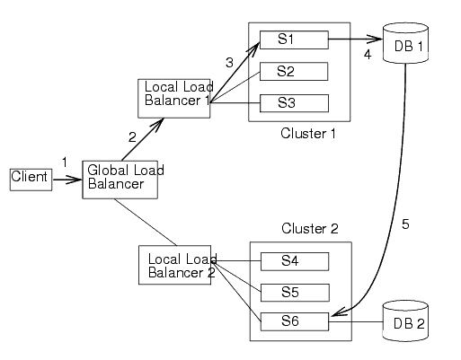
This section discusses possible failover scenarios across multiple clusters within a WAN. Figure 5-7 shows a typical multi-cluster environment within a WAN. Figure 6-7 WAN Replication
This figure demonstrates the following HTTP session state scenario:
- A client makes a request which passes through the global load balancer.
- The global load balancer passes the request to a local load balancer based on current system load. In this case, the session request is passed to Local Load Balancer 1.
- The local load balancer in turn passes the request to a server within a cluster based on system load, in this case S1. Once the request reaches S1, this managed server becomes the primary server for this HTTP session. This server will handle subsequent requests assuming there are no failures.
- Session state information is stored in the database of the primary cluster.
- After the server establishes the HTTP session, the current session state is replicated to the designated secondary server.
Failover Scenarios Within a WAN
This section describes the failover scenario within a WAN environment.
Failover Scenario
If all of the servers in Cluster 1 fail, the global load balancer will automatically fail all subsequent session requests to Cluster 2. All sessions will be backed up according to the last know flush to the database.Database Configuration for WAN Session State Replication
This section describes the data source configuration requirements for cross-cluster session state replication in a WAN. For more general information about setting up cross-cluster replication, see Configuration Requirements for Cross-Cluster Replication.
To enable cross-cluster replication within a WAN environment, create a JDBC data source that points to the database where session state information is stored. Perform the following procedures to setup and configure your database:
- Install and configure your database server software according to your vendor's documentation.
- Create a JDBC data source that references this database. For more information on creating a JDBC datasource, see
“Configuring JDBC Data Sources” in Configure WebLogic JDBC.
This data source can also be configured as a JDBC Multi Data Source. For more information on configuring a Multi Data Source, see “Configuring JDBC Multi Data Sources” in Configure WebLogic JDBC.
- Set the DataSourceForSessionPersistence for both the primary and secondary cluster to point to this data source.
- Create a table called WLS_WAN_PERSISTENCE in your database according to the following schema:
CREATE TABLE WLS_WAN_PERSISTENCE_TABLE (

  WL_ID VARCHAR2(100) NOT NULL,

  WL_CONTEXT_PATH VARCHAR2(50) NOT NULL,

  WL_CREATE_TIME NUMBER(20),

  WL_ACCESS_TIME NUMBER(20),

  WL_MAX_INACTIVE_INTERVAL NUMBER(38),

  WL_VERSION NUMBER(20) NOT NULL,

  WL_INTERNAL_ATTRIBUTE NUMBER(38),

  WL_SESSION_ATTRIBUTE_KEY VARCHAR2(100),

  WL_SESSION_ATTRIBUTE_VALUE LONG RAW,

  PRIMARY KEY(WL_ID, WL_CONTEXT_PATH,

  WL_VERSION, WL_SESSION_ATTRIBUTE_KEY));
The following table describes what each row of this table contains:
Replication and Failover for EJBs and RMIs
For clustered EJBs and RMIs, failover is accomplished using the object's replica-aware stub. When a client makes a call through a replica-aware stub to a service that fails, the stub detects the failure and retries the call on another replica.
With clustered objects, automatic failover generally occurs only in cases where the object is idempotent. An object is idempotent if any method can be called multiple times with no different effect than calling the method once. This is always true for methods that have no permanent side effects. Methods that do have side effects have to be written with idempotence in mind.
Consider a shopping cart service call addItem() that adds an item to a shopping cart. Suppose client C invokes this call on a replica on Server S1. After S1 receives the call, but before it successfully returns to C, S1 crashes. At this point the item has been added to the shopping cart, but the replica-aware stub has received an exception. If the stub were to retry the method on Server S2, the item would be added a second time to the shopping cart. Because of this, replica-aware stubs will not, by default, attempt to retry a method that fails after the request is sent but before it returns. This behavior can be overridden by marking a service idempotent.
Clustering Objects with Replica-Aware Stubs
If an EJB or RMI object is clustered, instances of the object are deployed on all WebLogic Server instances in the cluster. The client has a choice about which instance of the object to call. Each instance of the object is referred to as a replica.
The key technology that supports object clustering objects in WebLogic Server is the replica-aware stub. When you compile an EJB that supports clustering (as defined in its deployment descriptor), appc passes the EJB's interfaces through the rmic compiler to generate replica-aware stubs for the bean. For RMI objects, you generate replica-aware stubs explicitly using command-line options to rmic, as described in “WebLogic RMI Compiler” in Programming WebLogic RMI.
A replica-aware stub appears to the caller as a normal RMI stub. Instead of representing a single object, however, the stub represents a collection of replicas. The replica-aware stub contains the logic required to locate an EJB or RMI class on any WebLogic Server instance on which the object is deployed. When you deploy a cluster-aware EJB or RMI object, its implementation is bound into the JNDI tree. As described in Cluster-Wide JNDI Naming Service, clustered WebLogic Server instances have the capability to update the JNDI tree to list all server instances on which the object is available. When a client accesses a clustered object, the implementation is replaced by a replica-aware stub, which is sent to the client.
The stub contains the load balancing algorithm (or the call routing class) used to load balance method calls to the object. On each call, the stub can employ its load algorithm to choose which replica to call. This provides load balancing across the cluster in a way that is transparent to the caller. To understand the load balancing algorithms available for RMI objects and EJBs, see Load Balancing for EJBs and RMI Objects. If a failure occurs during the call, the stub intercepts the exception and retries the call on another replica. This provides a failover that is also transparent to the caller.
Clustering Support for Different Types of EJBs
EJBs differ from plain RMI objects in that each EJB can potentially generate two different replica-aware stubs: one for the EJBHome interface and one for the EJBObject interface. This means that EJBs can potentially realize the benefits of load balancing and failover on two levels:
- When a client looks up an EJB object using the EJBHome stub
- When a client makes method calls against the EJB using the EJBObject stub
The following sections describe clustering support for different types of EJBs.
Clustered EJBHomes
All bean homes interfaces—used to find or create bean instances—can be clustered, by specifying the determined by the home-is-clusterable element in weblogic-ejb-jar.xml.
Stateless session beans, stateful session beans, and entity beans have home interfaces. Message-driven beans do not.
When a bean is deployed to a cluster, each server binds the bean's home interface to its cluster JNDI tree under the same name. When a client requests the bean's home from the cluster, the server instance that does the look-up returns a EJBHome stub that has a reference to the home on each server.
When the client issues a create() or find() call, the stub routes selects a server from the replica list in accordance with the load balancing algorithm, and routes the call to the home interface on that server. The selected home interface receives the call, and creates a bean instance on that server instance and executes the call, creating an instance of the bean.
WebLogic Server supports load balancing algorithms that provide server affinity for EJB home interfaces. To understand server affinity and how it affects load balancing and failover, see Round-Robin Affinity, Weight-Based Affinity, and Random-Affinity.
Clustered EJBObjects
An EJBObject stub tracks available replicas of an EJB in a cluster.
Stateless Session Beans
When a home creates a stateless bean, it returns a EJBObject stub that lists all of the servers in the cluster, to which the bean should be deployed. Because a stateless bean holds no state on behalf of the client, the stub is free to route any call to any server that hosts the bean. The stub can automatically fail over in the event of a failure. The stub does not automatically treat the bean as idempotent, so it will not recover automatically from all failures. If the bean has been written with idempotent methods, this can be noted in the deployment descriptor and automatic failover will be enabled in all cases.
WebLogic Server supports load balancing options that provide server affinity for stateless EJB remote interfaces. To understand server affinity and how it affects load balancing and failover, see Round-Robin Affinity, Weight-Based Affinity, and Random-Affinity.
Stateful Session Beans
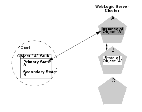
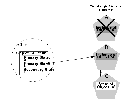
Method-level failover for a stateful service requires state replication. WebLogic Server satisfies this requirement by replicating the state of the primary bean instance to a secondary server instance, using a replication scheme similar to that used for HTTP session state.
When a home interface creates a stateless session bean instance, it selects a secondary instance to host the replicated state, using the same rules defined in Using Replication Groups. The home interface returns a EJBObject stub to the client that lists the location of the primary bean instance, and the location for the replicated bean state.
The following figure shows a client accessing a clustered stateful session EJB. Figure 6-8 Client Accessing Stateful Session EJB
As the client makes changes to the state of the EJB, state differences are replicated to the secondary server instance. For EJBs that are involved in a transaction, replication occurs immediately after the transaction commits. For EJBs that are not involved in a transaction, replication occurs after each method invocation.
In both cases, only the actual changes to the EJB's state are replicated to the secondary server. This ensures that there is minimal overhead associated with the replication process.
The actual state of a stateful EJB is non-transactional, as described in the EJB specification. Although it is unlikely, there is a possibility that the current state of the EJB can be lost. For example, if a client commits a transaction involving the EJB and there is a failure of the primary server before the state change is replicated, the client will fail over to the previously-stored state of the EJB. If it is critical to preserve the state of your EJB in all possible failover scenarios, use an entity EJB rather than a stateful session EJB.
Failover for Stateful Session EJBs
Should the primary server fail, the client's EJB stub automatically redirects further requests to the secondary WebLogic Server instance. At this point, the secondary server creates a new EJB instance using the replicated state data, and processing continues on the secondary server.
After a failover, WebLogic Server chooses a new secondary server to replicate EJB session states (if another server is available in the cluster). The location of the new primary and secondary server instances is automatically updated in the client's replica-aware stub on the next method invocation, as shown below. Figure 6-9 Replica Aware Stubs are Updated after Failover
Entity EJBs
There are two types of entity beans to consider: read-write entity beans and read-only entity beans.
- Read-Write Entities
When a home finds or creates a read-write entity bean, it obtains an instance on the local server and returns a stub pinned to that server. Load balancing and failover occur only at the home level. Because it is possible for multiple instances of the entity bean to exist in the cluster, each instance must read from the database before each transaction and write on each commit.
- Read-Only Entities
When a home finds or creates a read-only entity bean, it returns a replica-aware stub. This stub load balances on every call but does not automatically fail over in the event of a recoverable call failure. Read-only beans are also cached on every server to avoid database reads.
Failover for Entity Beans and EJB Handles
Failover for entity beans and EJB handles depends upon the existence of the cluster address. You can explicitly define the cluster address, or allow WebLogic Server to generate it automatically, as described in Cluster Address. If you explicitly define cluster address, specify it as a DNS name that maps to all server instances in the cluster and only server instances in the cluster. The cluster DNS name should not map to a server instance that is not a member of the cluster.
Clustering Support for RMI Objects
WebLogic RMI provides special extensions for building clustered remote objects. These are the extensions used to build the replica-aware stubs described in the EJB section. For more information about using RMI in clusters, see “WebLogic RMI Features” in Programming WebLogic RMI.
Object Deployment Requirements
If you are programming EJBs to be used in a WebLogic Server cluster, read the instructions in this section to understand the capabilities of different EJB types in a cluster. Then ensure that you enable clustering in the EJB's deployment descriptor. See “weblogic-ejb-jar.xml Deployment Descriptor Reference” in Programming WebLogic Enterprise JavaBeans for information about the XML deployment elements relevant for clustering.
If you are developing either EJBs or custom RMI objects, also refer to “ Using WebLogic JNDI in a Clustered Environment” in Programming WebLogic JNDI to understand the implications of binding clustered objects in the JNDI tree.
Other Failover Exceptions
Even if a clustered object is not idempotent, WebLogic Server performs automatic failover in the case of a ConnectException or MarshalException. Either of these exceptions indicates that the object could not have been modified, and therefore there is no danger of causing data inconsistency by failing over to another instance.
Failover and JDBC Connections
JDBC is a highly stateful client-DBMS protocol, in which the DBMS connection and transactional state are tied directly to the socket between the DBMS process and the client (driver). For this reason, failover of a connection is not supported. If a WebLogic Server instance dies, any JDBC connections that it managed will die, and the DBMS(s) will roll back any transactions that were under way. Any applications affected will have to restart their current transactions from the beginning. All JDBC objects associated with dead connections will also be defunct. Clustered JDBC eases the reconnection process: the cluster-aware nature of WebLogic data sources in external client applications allow a client to request another connection from them if the server instance that was hosting the previous connection fails.
If you have replicated, synchronized database instances, you can use a JDBC multi data source to support database failover. In such an environment, if a client cannot obtain a connection from one data source in the multi data source because the data source doesn't exist or because database connectivity from the data source is down, WebLogic Server will attempt to obtain a connection from the next data source in the list of data sources.
For instructions on clustering JDBC objects, see Configure Clustered JDBC.
Any data source assigned to a multi data source must be configured to test its connections at reserve time. This is the only way a pool can verify it has a good connection, and the only way a multi data source can know when to fail over to the next pool on its list.
