11.3.1 Configure basic High Availability

When you are using the High Availability feature of Load Balancer, you do not use the dscontrol executor configure command in the Dispatcher configuration file. Leaving the command in the configuration would break the High Availability configuration because it adds the IP aliases to the network interface no matter what the state of the Load Balancer server is (active or standby). We need to make sure that the IP aliases are only added to the network interface when a server changes to the active state. For a High Availability configuration, we create scripts that control all IP aliases that need to be added or removed from the network interfaces and the loopback interface, as described in 11.3.4, Configuring the High Availability scripts.

First, we have to remove the cluster IP alias from the existing configuration before proceeding:

1.xxxx

Open the Load Balancer GUI and connect to the primary server as described in steps 1 through 4. Make sure that the correct configuration is loaded by checking that the cluster, port, and servers are already configured.

2.xxxx

Right-click Executor and select Unconfigure Interface Address, as shown in Figure 11-45, for the MAC configuration. For NAT, you need to unconfigure both the cluster address and the return address.

Figure 11-45 Unconfiguring the cluster address

A pop-up window is displayed. Enter the IP address of the cluster in the Interface address field. In our scenario, we want to remove the IP alias for the cluster address 9.26.126.103, as shown in Figure 11-46.


Figure 11-46 Specifying the IP address to unconfigure

3.xxxx

Save the current configuration, then copy it to the Standby Load Balancer so that you do not need to set up the basic load balancing configuration there again.

Note: The menu choice Host:... > Save Configuration File As... prompts you for a filename, but with Load Balancer V6.0.2 on AIX it seems that the currently used configuration file is always overwritten, no matter which filename is specified. Therefore, IBM recommends making a backup of the file and then having it overwritten with the new configuration. The configuration files are stored in LoadBalancer_Install_Dir/servers/configurations/dispatcher on AIX and Solaris.

4.xxxx

Now we need to add the High Availability configuration. Right-click High Availability in the left pane of the GUI window and select Add High Availability Backup, as shown in Figure 11-47.

Figure 11-47 Starting the High Availability configuration

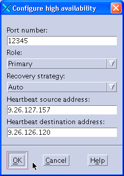
A new pop-up window is displayed, as shown in Figure 11-48.


Figure 11-48 Configuring High Availability options

In order to monitor the health of the active server, heartbeats are sent every half second. The failover occurs when the standby server receives no response from the active server within two seconds.

a.xxxx Choose a port number that will be used by both Load Balancer servers to exchange the information needed to keep them synchronized and put it in the Port number field. You can choose any port-you just need to make sure that the port number matches on both servers.
b.xxxx In the Role field, select the role that this machine will have in the High Availability scenario (Primary, Backup, or Both). In our scenario, this machine is our primary machine, so we select Primary.
c.xxxx In the Recovery strategy field, choose how your primary machine is going to behave in case the backup machine has taken over. Select Auto for automatic takeover as soon as it is up and responding to the network. Select Manual for manual takeover (either by selecting High Availability Æ Takeover in the tree view of the Load Balancer GUI, or by running the command dscontrol high takeover).
d.xxxx The last thing that you need to add in this window is the heartbeat source address and the heartbeat destination address. The heartbeat is a Generic Route Encapsulation (GRE) packet that is sent from the local machine to the other server in the same High Availability cluster to make sure that it is responding. Enter the IP address of the local machine into the Heartbeat source address field, and the IP address of the standby machine into the Heartbeat destination address field.
e.xxxx When you are finished, click OK.

5.xxxx

Open the Load Balancer GUI and connect to the backup server as described in steps 1 through 4. Select your backup server in the Dispatcher Login pop-up, as shown in Figure 11-50.

Figure 11-50 Connecting the GUI to a host

6.xxxx

Load the configuration file that you copied from the primary server in step 3. Right-click Host: srvb501.torolab.ibm.com and select Load New Configuration, as shown in Figure 11-51.

Figure 11-51 Loading a new configuration

Select the filename in the pop-up window and click OK. See Figure 11-52.


Figure 11-52 Selecting a configuration file

7.xxxx

We now need to configure the balanced servers' collocation settings. For our scenario, we installed the primary Load Balancer on Web server node 2 and set the collocation flag to yes in step Figure 14. On the Standby Load Balancer machine, we need to change this setting back to no.

Similarly, if the Standby Load Balancer is installed on the same machine as one of the load-balanced Web servers, we need to set that server's collocation flag to yes. This is the case in our scenario where the Standby Load Balancer is installed on Web server node 1.

The flag has to be changed for all occurrences of the respective balanced server under the balanced ports.

Again, when changing a server's configuration, do not forget to click the Update Configuration button.

8.xxxx

Add the High Availability information for the backup server. Right-click High Availability in the left pane of the GUI window and select Add High Availability Backup (this is the same procedure that we performed for the primary server in step 4).

You need to use the same parameters for Port number and Recovery strategy that you used in the configuration of the primary server (see Figure 11-27).

Select Backup in the Role field.

For the backup server, the heartbeat source address is the standby server itself, and the heartbeat destination address is the primary server, as shown in Figure 11-53.


Figure 11-53 Configure High Availability

9.xxxx

Save the configuration of the primary and backup servers.

Refer to 11.3.3, Command-line configuration, for the complete configuration files of both Load Balancer servers.

For both servers, when selecting High Availability in the tree view on the left side of the GUI, the High Availability status window should now show the correct states (active or standby) and sub-state (synchronized), as shown in Figure 11-54 and Figure 11-55.

Figure 11-54 Primary Load Balancer status after High Availability configuration

Figure 11-55 Standby Load Balancer status after High Availability configuration

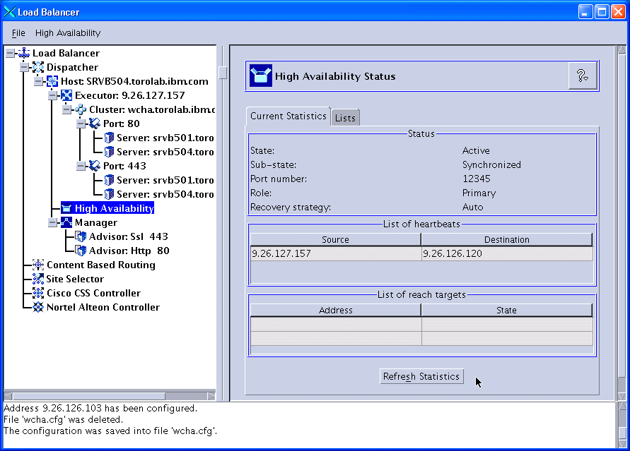
f.xxxx For now, the configuration is done on the primary server. Click High Availability in the left pane, and you can see the High Availability status information in the right pane, as shown in Figure 11-49.

Figure 11-49 High Availability status

The next steps must be performed on the standby Standby Load Balancer server, which in our scenario is the server srvb501.torolab.ibm.com.

xxxx