|
Setting up virtual devicesThis section explains how to set up virtual devices, within the VIO Server, that need to be connected to the Partition Profile.
Naming conventionsIn addition to using a tracking tool such as a spreadsheet, a useful naming convention is key to managing this information. One strategy for reducing the amount of data that must be tracked is to make device names and slots match on the virtual I/O client and server wherever possible. This convention could include corresponding volume group, logical volume, and virtual target device names. Integrating the virtual I/O client host name into the virtual target device name can simplify tracking on the server.
Device slot numbersAfter naming conventions have been established, slot numbering conventions should also be established for the virtual I/O adapters. Slot numbers are shared between virtual storage and virtual network devices. In complex systems there will tend to be far more storage devices than network devices because each virtual SCSI device can only communicate with one server or client. IBM recommends that you reserve the slot numbers through 20 for network devices on all LPARs, to keep the network and storage devices grouped together. Management can be simplified by keeping slot numbers consistent between the virtual I/O client and server. However, when partitions are moved from one server to another, this may not be possible. In environments with only one VIO Server, storage adapters should be added incrementally starting with slot 21 and higher. When clients are attached to two VIO Servers, the adapter slot numbers should be alternated from one VIO Server to the other. The first VIO Server should use odd numbered slots starting at 21, and the second VIO Server should use even numbered slots starting at 22. In a two-server scenario, slots should be allocated in pairs, with each client using two adjacent slots such as 21 and 22, or 33 and 34. The maximum number of virtual adapter slots per LPAR should be increased above the default value of ten when you create an LPAR. The appropriate number for your environment depends on the number of LPARs and adapters expected on each system. Each unused virtual adapter slot consumes a small amount of memory, so the allocation should be balanced. Use the System Planning Tool, which is available from the following URL, to plan memory requirements for your system configuration: http://www.ibm.com/servers/eServer/iseries/lpar/systemdesign.html Because VSCSI connections operate at memory speed, there is generally no performance gain from adding multiple adapters between a VIO Server and client. Each adapter pair can handle large numbers of target devices, or disks. In our case, we used the assignment definition listed in Table 3-5. Table 3-5 Server and Client Slot ID definitions
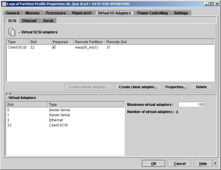
We used a value of 100 as shown in Figure 3-17 for the VIO Server Profile using HMC GUI.
Figure 3-17 Maximum virtual adapters setting Figure 3-18 shows the final VIO Partition Properties after the physical and virtual disks are all mapped together.
Managing and exporting physical storage on the VIO ServerThe Virtual I/O Server presents disk storage to virtual I/O clients (VIOCs) as virtual SCSI disks. These virtual disks must be mapped to physical storage by the VIO Server. There are three different ways to perform this mapping, each with its own advantages:
The general rule for selecting between these options is that disk devices being accessed through a SAN should be exported as physical volumes, with storage allocation managed in the SAN. Internal and SCSI attached disk devices should be exported with either logical volumes or storage pools so that storage can be located within the server. A single volume group should not contain logical volumes used by virtual I/O clients and logical volumes used by the VIO Server operating system. Keep VIO Server file systems within the rootvg, and use other volume groups to host logical volumes for virtual I/O expanding the size of virtual storage devices. When exporting logical volumes to clients, the mapping of individual logical volumes to virtual I/O clients is maintained on the VIO Server. The additional level of abstraction provided by the logical volume manager makes it important to track the relationship between physical disk devices and virtual I/O clients. One strategy for reducing the amount of data that must be tracked is to make device names and slots match on the virtual I/O client and server wherever possible. This could include corresponding volume group, logical volume, and virtual target device names. Integrating the virtual I/O client host name into the virtual target device name can simplify tracking on the server. After naming conventions have been established, slot numbering conventions should also be established for the virtual I/O adapters. Slot numbers are shared between virtual storage and virtual network devices. When planning for the number of virtual I/O slots on your LPAR, the maximum number of virtual adapter slots available on a partition is set by the partition's profile. To change this profile, shut down the LPAR. IBM recommends leaving plenty of room for expansion when setting the maximum number of slots so that new virtual I/O clients can be added without shutting down the LPAR or VIO Server partition. Despite the best intentions in record keeping, it sometimes becomes necessary to manually trace a client virtual disk back to the physical hardware. The IBM Systems Hardware Information Center contains a guide to tracing virtual disks. At the following URL, search for "Mapping virtual disks to physical disks". Be sure to include the quotes when you enter the search string. Depending on which method you choose, you may need to track the following information:
Figure 3-18 Exported VIO disk mapping Figure 3-18 illustrates mapping between physical storage, VIO Server and client. On the VIO Server, hdisk2 has been assigned to the volume group applvg_clients. On this volume group, we created a logical volume applvg_uk. This logical volume is connected as a virtual disk to the LPAR uk_lpar. When we logged on to the partition uk.itsc.austin.ibm.com, AIX mapped the virtual device as hdisk1, which was assigned to the volume group appl_vg. Example 3-9 displays the final result of using the command lspv on node uk executed through a dsh session of the Management Server madrid.itsc.austin.ibm.com. Example 3-9 lspv on system uk with the second virtual hdisk1 [2:root@MADRID:]/home/root # dsh -n uk "lspv" uk.itsc.austin.ibm.com: hdisk0 00c4790e281766f5 rootvg active uk.itsc.austin.ibm.com: hdisk1 00c4790ecd59fa72 appl_vg active
Creating the boot volume for the VIO SCSI client partitionsIn order to assign a boot volume to a partition that uses Virtual SCSI, you first need to create the volumes (physical and logical) on the VIO Server, and then create the virtual device for the client partition. In this section we demonstrate these tasks, using the definition shown in Figure 3-18. First, we executed the lspv command on the VIO Server. This showed that the devices hdisk1 and hdisk2 were available but unconfigured; see Example 3-10. Example 3-10 lspv output default vios output $ lspv NAME PVID VG STATUS hdisk0 000b7bac80a00769 rootvg active hdisk1 none None hdisk2 none None $ In our case, we want hdisk1 to hold all logical volumes and act as the boot volume, and hdisk2 to become our shared volume group. We created the volume group named rootvg_clients on hdisk1, as shown in Example 3-11. Example 3-11 Using the mkvg command to create rootvg_clients volume group $ mkvg -f -vg rootvg_clients hdisk1 rootvg_clients $ lspv NAME PVID VG STATUS hdisk0 000b7bac80a00769 rootvg active hdisk1 000b7bacc2fc3c83 rootvg_clients active hdisk2 none None $ The newly created volume group can now be used to hold all logical volumes. Next, we created the logical volume rootvg_uk, which will become the root volume group on partition uk; see Example 3-12. Example 3-12 Using the mklv command to create the rootvg_uk $ mklv -lv rootvg_uk rootvg_clients 20G rootvg_uk $ $ lsvg -lv rootvg_clients rootvg_clients: LV NAME TYPE LPs PPs PVs LV STATE MOUNT POINT rootvg_uk jfs 160 160 1 closed/syncd N/A $
We created the virtual device and vuk_rvg using the mkvdev command; see Example 3-13. Example 3-13 Using the mkvedv command to create virtual device vuk_rvg $mkvdev -vdev rootvg_uk -vadapter vhost0 -dev vuk_rvg $vuk_rvg Available Example 3-14 and Example 3-15 illustrate the relationship between the Virtual SCSI disk on the VIO Server and the client. On the VIO Server we used the command lsmap to display the mapping between the physical, logical, and virtual devices; see Example 3-14. Example 3-14 Virtual device map for node uk on VIO $lsmap -vadapter vhost2 SVSA Physloc Client Partition ID --------------- ----------------------------------- ------------------ vhost2 U9133.55A.10D1FAG-V1-C51 0x00000004
VTD vuk_rvg LUN 0x8100000000000000 Backing device rootvg_uk Physloc # Notice that the logical volume rootvg_uk device is mapped as vuk_rvg through the server virtual adapter (SVSA) vhost2, which has the physical location code U9133.55A.10D1FAG-V1-C51. (This is also shown in Figure 3-21.) Next, we created a listing of the vital product data by using the commands lscfg and lspv on node uk.itsc.austin.ibm.com. As you can see in Example 3-15, hdisk0 is mapped to the physical location U9133.55A.10D1FAG-V4-C52. Also note that the locations U9133.55A.10D1FAG-V1-C51 and U9133.55A.10D1FAG-V4-C52 reflect to the virtual devices slot numbers as defined in Device slot numbers and Table 3-5. Example 3-15 Virtual device configuration on node uk #dsh -n uk "lscfg -vl hdisk0" uk.itsc.austin.ibm.com: hdisk0 U9133.55A.10D1FAG-V4-C52-T1-L810000000000 Virtual SCSI Disk Drive #dsh -n uk lspv uk.itsc.austin.ibm.com: hdisk0 000b7bacc8a01fdf rootvg active
At this point, we finalized the preparation for our partitions before installing the base operating system.
Networking on the VIO ServerThe VIO Server can be accessed from the HMC by using a secure private HMC-to-Service Processor network to open a console session. This makes a dedicated network address on the VIO Server for administration optional. However, if the VIO Server does not appear on any network at all, dynamic resource allocation will not be enabled for the VIO Server because there is no way to connect to it. One key to managing a virtual environment is keeping track of which virtual objects correspond to which physical objects. In the network area, this can involve physical and virtual network adapters and VLANs that span hosts and switches. Depending on whether you choose to use 802.1Q tagged VLANs, you may need to track the following information:
Slot numbers are shared between virtual storage and virtual network devices. In complex systems there will tend to be far more storage devices than network devices, because each virtual SCSI device can only communicate with one server or client. IBM recommends that you reserve slot numbers through 20 for network devices on all LPARs in order to keep the network devices grouped together; refer to Device slot numbers for details.
Setting up a Shared Ethernet Adapter (SEA) on the VIO ServerVirtual devices must be created on the Partition profile level through the HMC. We changed the current Partition profile using default settings, as shown in Figure 3-19.
Figure 3-19 Virtual Ethernet configuration for VIO Server using the HMC Because the change has been applied to the current partition profile, a reboot of the VIO Server is required. In Example 3-16 you can see that the virtual adapter ent2 is mapped to the physical adapter ent0. Also note that the second physical adapter ent1 is not in use at this point. We need to be in the from the oem_setup_env session on the VIO Server to be able to execute the command. Example 3-16 VIO initial virtual Ethernet Adapter state # lscfg -l ent\* ent2 U9133.55A.10D1FAG-V1-C2-T1 Virtual I/O Ethernet Adapter (l-lan) ent0 U787B.001.DNWB206-P1-T9 2-Port 10/100/1000 Base-TX PCI-X Adapter (14108902) ent1 U787B.001.DNWB206-P1-T10 2-Port 10/100/1000 Base-TX PCI-X Adapter (14108902)
Next, we created the SEA, using the mkvdev -sea option for the virtual adapter ent2. We used the command lsdev to verify that the adapter has been created; see Example 3-17. Example 3-17 Virtual Ethernet ent2 status $mkvdev -sea ent0 -vadapter ent2 -default ent2 -defaultid 2 $lsdev -dev ent2 name status description ent2 Available Virtual I/O Ethernet Adapter (l-lan)
We created the Ethernet TCPIP Interface, which enables TCP/IP traffic. The Virtual Interface Name generated by the command mkvdev must be used. In our case, it was interface en3; see Example 3-18. Example 3-18 Running mktcpip on VIO Virtual Ethernet $mktcpip -hostname wasp5l_vio -inetaddr 9.3.5.170 -interface en3 -netmask 255.255.255.0 -gateway 9.3.5.41 $lsdev -dev en3 name status description en3 Available Standard Ethernet Network Interface Now we were ready to use the Shared Virtual Ethernet Interface, which could be used by other LPARs without the need to assign more physical Ethernet adapters to each of them. The Virtual Adapter must be created in the Partition Profile, as shown in Figure 3-20.
Figure 3-20 Virtual Ethernet configuration for client partition using the HMC |