Guidelines: Reverse-engineering
Relational Databases
Topics
- Introduction
- Reverse Engineering RDBMS Database or DDL Script to Generate a Data Model
- Transforming Data Model
Elements
to Design Model Elements
- Identify Embedded or Implicit Classes
- Handle Foreign-Key Relationships
- Handle Many-to-Many Relationships
- Introduce Generalization
- Replicating RDBMS Behavior in the Design Model
- Organize Elements in the Design Model
Introduction
This guideline describes the steps involved in reverse engineering a database and mapping the resulting Data Model tables to Design Classes in the Design Model. This process may be used by the Database Designer to seed the development of modifications to the database as part of an evolution development cycle. The Database Designer will need to manage the reverse engineering process throughout the development lifecycle of the project. In many cases, the reverse engineering process is performed early in the project lifecycle and then changes to the data design are managed incrementally without the need to perform subsequent reverse engineering of the database.
The major steps in the process for reverse engineering a database and transforming the resulting Data Model elements into Design Model elements are as follows:
- Create a physical Data Model containing tables to represent the physical layout of persistent data in the database. This step may be performed automatically using tools supplied with the Relational Database Management System (RDBMS) or through most modern visual modeling tools.
- Transform the tables in the physical Data Model into Design Classes in the Design Model. This step can be performed through a combination of automated tool support for the initial transformation followed by manual adjustments.
- Define associations between the classes in the Design Model.
- Define appropriate operations on the classes in the Design Model based on the actions performed on the corresponding Data Model elements.
- Group the classes in the Design Model into subsystems and packages as needed.
Reverse Engineering RDBMS Database or DDL script to Generate a Data Model
The database or Data Definition Language (DDL) script reverse engineering process typically yields a set of model elements (tables, views, stored procedures, etc.) into one or more system defined packages in the Data Model. Depending on the complexity of the database, the database designer may need to partition the reverse engineered model elements into subject area packages that contain logically related sets of tables.
Transforming Data Model to Design Model
The following procedure can be followed to produce Design Classes from model elements in the Data Model. Replicating the structure of the database in a class model is relatively straight-forward. The process listed below describes the algorithm for transforming Data Model elements to Design Model elements.
The table below shows a summary of the general mapping between Design Model elements and Data Model elements.
Data Model Element | Corresponding Design Model Element |
|---|---|
| Table | Class |
| Column | Attribute |
Non-Identifying Relationship | |
Intersection Table |
Association Class Many-to-Many Association Qualified Association |
Identifying Relationship | |
Cardinality | Multiplicity |
| Check Constraint with an enumerated clause | <<ENUM>> Class |
| Schema | Package |
There are some model elements in the Data Model that have no direct correlation in the Design Model. These elements include the Tablespaces and the Database itself, which model the physical storage characteristics of the database and are represented as components. Another item is database views, which are "virtual" tables and have no meaning in the Design Model. Finally, indexes on primary keys of tables and database trigger functions, which are used to optimize the operation of the database have meaning only in the context of the database and the Data Model.
Transform a Table to a Class
For each table you wish to transform, create a class to represent the table. For each column, create an attribute on the class with the appropriate data type. Try to match the data type of the attribute and the data type of the associated column as closely as possible.
Example
Consider the database table Customer, with the following structure, shown in the following figure:
| Column Name | Data Type |
|---|---|
| Customer_ID | Number |
| Name | Varchar |
| Street | Varchar |
| City | Varchar |
| State/Province | Char(2) |
| Zip/Postal Code | Varchar |
| Country | Varchar |
Table definition for Customer table
Starting from this point, we create a class, Customer, with the structure shown in the following figure:
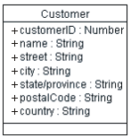
Initial Customer class
In this initial Customer class, there is an attribute for each column in the Customer table. Each attribute has public visibility, since any of the columns in the originating table may be queried.
Note, the "+" icon listed to the left of the attribute indicates that the attribute is 'public'; by default, all attributes derived from RDBMS tables should be public, since the RDBMS generally allows any column to be queried without restriction.
Identify Embedded or Implicit Classes
The class that results from the direct table-class mapping will often contain attributes that can be separated into a separate class, especially in cases where the attributes appear in a number of translated classes. These 'repeated attributes' may have resulted from denormalization of tables for performance reasons, or may have been the result of an oversimplified Data Model. In these cases, split the corresponding class into two or more classes to represent a normalized view of the tables.
Example
After defining the Customer class above, we can define an Address class which contains all address information (assuming that there will be other things with addresses in our system), leaving us with the following classes:
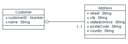
revised Customer class, with extracted Address class
The association drawn between these two is an aggregation, since the customer's address can be thought of as being part-of the customer.
Handle Foreign-Key Relationships
For each foreign-key relationship in the table, create an association between the associated classes, removing the attribute from the class which mapped to the foreign-key column. If the foreign-key column was represented initially as an attribute, remove it from the class.
Example
Assume the structure for the Order table listed below:
| Column Name | Data Type |
|---|---|
| Number | Number |
| Customer_ID | Varchar |
Structure for the Order table
In the Order table listed above, the Customer_ID column is a foreign-key reference; this column contains the primary key value of the Customer associated with the Order. We would represent this in the Design Model as shown below:
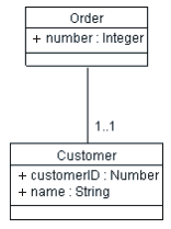
Representation of foreign-key Relationships in the Design Model
The foreign-key is represented as an association between the classes Order and Item.
Handle Many-to-Many Relationships
RDBMS data models represent many-to-many relationships with what has been called a join table, or an association table. These tables enable many-to-many relationships to be represented using an intermediate table which contains the primary keys of two different tables which may be joined together. The reason join tables are needed is because a foreign key reference can only contain a reference to a single foreign key value; when a single row may relate to many other rows in another table, a join table is needed to associate them.
Example
Consider the case of Products, which may be provided by any one of a number of Suppliers, and any Supplier may provide any number of Products. The Product and Supplier tables have the structure defined below:
|
|
Product and Supplier Table Definitions
In order to link these two tables together to find the products offered by a particular supplier, we need a Product-Supplier table, which is defined in the table below.
| Product-Supplier Table | |
|---|---|
| Column Name | Data Type |
| Product_ID | Number |
| Supplier_ID | Number |
Product-Supplier Table Definition
This join table contains the primary keys of products and suppliers, linking them together. A row in the table would indicate that a particular supplier offers a particular product. All rows whose Supplier_ID column matches a particular supplier ID would provide a listing of all products offered by that supplier.
In the Design Model, this intermediate table is redundant, since an object model can represent many-to-many associations directly. The Supplier and Product classes and their relationships are shown in the figure below, along with the Address class, which is extracted from the Supplier, according to the previous discussion.
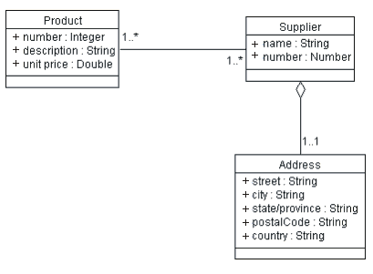
Product and Supplier Class Representation
Introduce Generalization
Often, you will find tables which have some similar structure. In the Data Model, there is no concept of generalization, so there is no way to represent that two or more tables have some structure in common. Sometimes common structure results from denormalization for performance, such as was the case above with the 'implicit' Address table which we extracted into a separate class. In other cases, tables share more fundamental characteristics which we can extract into a generalized parent class with two or more sub-classes. To find generalization opportunities, look for repeated columns in several tables, where the tables are more similar than they are different.
Example
Consider the following tables, SoftwareProduct and HardwareProduct, as shown below:
|
|
SoftwareProduct and HardwareProduct Tables
Notice that the columns highlighted in blue are identical; these two tables share most of their definition in common, and only differ slightly. We can represent this by extracting a common Product class, with SoftwareProduct and HardwareProduct as sub-classes of the Product, as shown in the following figure:
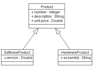
SoftwareProduct and HardwareProduct Classes, showing generalization to the Product class
Putting all of the class definitions together, the figure below shows a consolidated class diagram for the Order Entry system (major classes only).
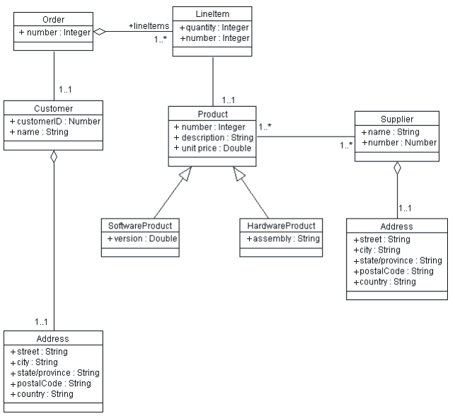
Consolidated Class diagram for the Order Entry System
Replicating RDBMS Behavior in the Design Model
Replicating behavior is more difficult, since typically relational databases are not object-oriented and do not appear to have anything analogous to operations on a class in the object model. The following steps can help re-construct the behavior of the classes identified above:
- Create operations to get and set each attribute. There needs to be a way to set, change and query the values of the attributes of objects. Since the only way to access the attributes of an object is through operations the class provides, such operations must be defined on the class. When creating the operations that set the value of an attribute, be sure to incorporate any validation constraints that may operate on the associated column. If there are no validation constraints, one may choose to simply represent the fact that the attributes can be get and set by marking them as having "public" visibility, as this has been done in the diagrams above (with the icon to the left of the attribute name).
- Create an operation on the class for each stored procedure which operates upon the associated table. Stored procedures are executable subroutines which execute within the DBMS itself. This logic needs to be translated into the Design Model. If a stored procedure operates only on one class, create an operation on the class with the same parameters and the same return type as the stored procedure. Document the behavior of the stored procedure in the operation, making sure to note in the method description that the operation is implemented by the stored procedure.
- Create operations to manage associations between classes. When there is an association between two classes, there must be a way to create, manage and remove associations. Associations between objects are managed through object references, so to create an association between an Order and a LineItem (i.e. to add the LineItem to the Order), an operation on Order would be invoked, passing the LineItem as an argument (i.e. Order.add(aLineItem)). There must also be ways to remove and update the association as well (i.e. Order.remove(aLineItem) and Order.change(aLineItem,aNewLineItem)).
- Handle Object Deletion. If the target language supports explicit deletion, add behavior to the class's destructor which implements referential integrity checking. In cases where there are referential integrity constraints in the database, such as cascade delete, the behavior needs to be replicated in the appropriate classes. For example, the database may define a constraint that says that whenever an Order is deleted, all associated LineItems should be deleted as well. If the target language supports garbage collection, create a mechanism by which rows can be removed from tables when the associated object is garbage-collected. Note that this is harder than it sounds (and it sounds hard), because you will need to implement a mechanism for ensuring that no database client has any references to the object which is to be garbage collected; it is not enough to rely upon the garbage collection capabilities of the execution environment/virtual machine since this is simply one client's view of the world.
- Handle Behavior Implied by Queries. Examine Select statements which access the table to see how information is retrieved and manipulated. For each column directly returned by a Select statement, set the public property of the associated attribute to true; all other attributes should be private. For each computed column in a Select statement, create an operation on the associated class to compute and return the value. When considering Select statements, also include the Select statements embedded in View definitions.
Organize Elements in the Design Model
The Design Classes created from the table-to-class transformations should be organized into appropriate design packages and/or design subsystems in the Design Model, as needed, based on the overall architectural structure of the application. Refer to Concepts: Layering and Concepts: Software Architecture for an overview of application architecture.
