2. After starting Executor, click Executor: 9.26.52.215 in the left pane of the GUI window, and locate the Client gateway address field in the right pane (see Figure 11-29). This field needs to be filled in order to enable NAT/NAPT and CBR forwarding methods. This is the IP address of the gateway router that handles traffic from the cluster back to the client browser.
In our scenario, we used the default gateway IP address in our configuration, which is 9.26.52.1.
Important: We are using 9.26.52.1 because we use the same IP address for inbound and outbound traffic. In case you are not using a common IP address, you need to specify the IP address of the router that serves as the first hop on the way from the Load Balancer to the client.
Enter the correct IP address and click Update Configuration.
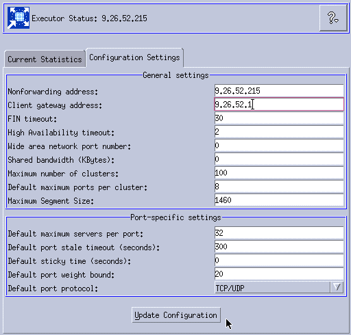
Figure 11-29 Configuring the client gateway address
3. After configuring the client gateway address, we need to configure the cluster. Right-click Executor: 9.26.52.215 in the left pane of the GUI and select Add Cluster, as shown in Figure 11-30.
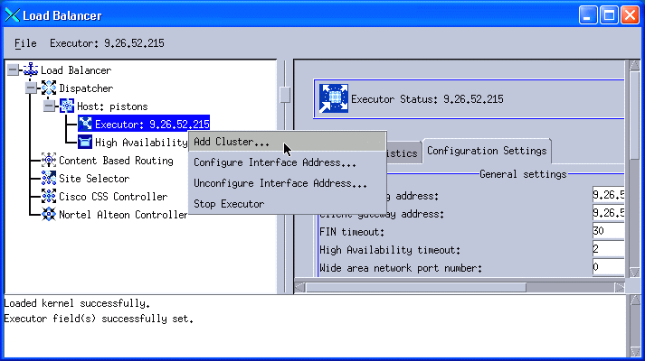
Figure 11-30 Add a cluster - NAT configuration
The information provided for the cluster creation is similar to what we used in the MAC scenario (see steps 6 through 8). Details are shown in Figure 11-31.
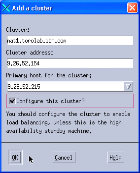
Figure 11-31 Cluster information
If you selected the Configure this cluster? check box, you need to also provide the information to add the IP alias, as shown in Figure 11-32. Note that on Solaris 9, the Ethernet network interface is called hme0.
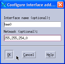
Figure 11-32 Configuring the interface
4. Right-click Cluster: nat1.torolab.ibm.com in the left pane and select Add Port, as shown in Figure 11-33.
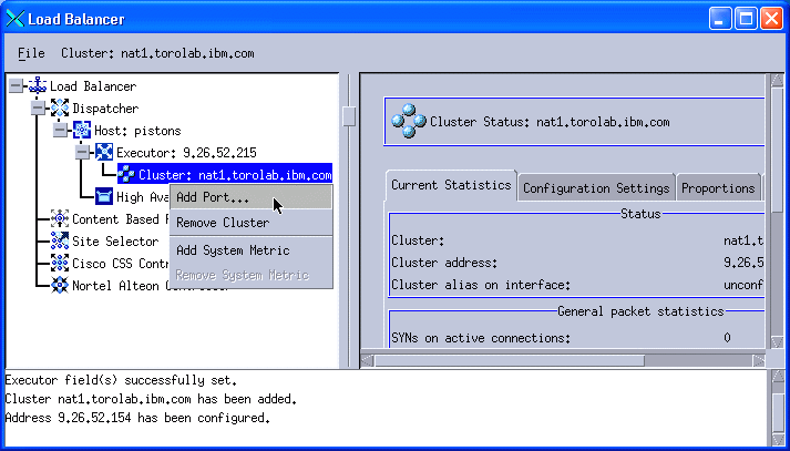
Figure 11-33 Add a port
A pop-up window is displayed similar to the one that we had in the NAT scenario. Type 80 into the Port number field, select NAT / NAPT as the Forwarding method, and click OK. See Figure 11-34.
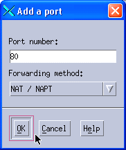
Figure 11-34 Adding a port - NAT forwarding method
5. Right-click Port: 80 in the left pane and select Add Server, as shown in Figure 11-35.

Figure 11-35 Add a server
A pop-up window is displayed, but it contains more fields compared to the one we got when configuring MAC forwarding.
The two extra fields are the return address and the network router address.
The return address is an extra IP address that is used by Dispatcher as the source IP address of the packets that are sent to the Web servers. You cannot use neither the cluster address or the non-forwarding address (NFA) as the return address, so you need one additional IP address for this configuration.
The network router address is the router that serves as the first hop on the way from the Load Balancer to the load balanced server. With our single subnet scenario, it is the same address as the client gateway. This field is provided in the server configuration in case you have several balanced servers spread in different remote networks, and you need a different router IP address to reach each server.
Note: When you configure NAT/NAPT on a collocated server, you need to use the local IP address as the network router address. This tells Dispatcher that the desired server is collocated on the local machine.
We added our first Web server, as shown in Figure 11-36. We used the same values that we used for MAC forwarding (see Figure 11-19) and we also provided the IP address we selected as our return address and our default gateway IP address as our network router address.
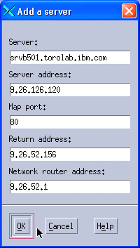
Figure 11-36 Adding the first balanced server
6. Add the second Web server. We used the same values for our second Web server as the ones we used for MAC forwarding, and we also used the same return address and the same network router address, as shown in Figure 11-37.
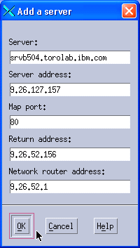
Figure 11-37 Adding the second balanced server
7. We also add a third server in a remote network, as shown in Figure 11-38.
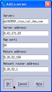
Figure 11-38 Adding the third balanced server
8. Repeat steps 4 through 7 for any other port for which you want to provide load balancing. We want to balance our store front (ports 80 and 443), but not the administration consoles (ports 8000, 8002, and so on), so we only add port 443 and add the three Web servers to it. Our final configuration is shown in Figure 11-40.
9. Follow steps 12 and 13 to start the manager and advisors.
10. The last thing that you need to configure is to add the return address to the operating system, so it is able to handle the responses from the balanced servers.
Important: It is sufficient to configure the return address if you are not in a collocated environment. If, however, your Load Balancer server is collocated, you need to perform additional steps. These differ for each operating system, so refer to Chapter 21, Section "Using collocated servers - Configuring server collocation with Dispatcher's NAT forwarding," in the Load Balancer Administration Guide, GC31-6858, for complete instructions for your operating system.
In the GUI, right-click Executor and select Configure Interface Address. Enter the return address into the Interface address field (in our example this is 9.26.52.156), type the interface name into the optional Interface name field (in our example this is hme0), and enter the netmask into the Netmask field (in our example this is 255.255.254.0). See Figure 11-39.
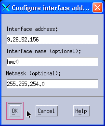
Figure 11-39 Configure the return address
11. Do not forget to save your configuration file as described in step 15.
When the configuration is complete, the tree view in the left pane of the GUI should look as shown in Figure 11-40.
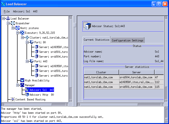
Figure 11-40 Complete NAT configuration


