5.5 WebSphere Application Server high availability deploymentsThe subject of deploying WebSphere Application Server in high availability configurations is covered in multiple places in this book. This section explains how to make WebSphere Application Server resilient and available by using the mechanism for high availability, consisting of Java components that are managed inside the WebSphere Application Server JVM process and those that are external to the WebSphere Application Server JVM process. Within the WebSphere Application Server JVM process, high availability is based on components that are active-active within a cluster, and stateless or made consistent across the cluster using the Data Replication Service (DRS) fast message queuing mechanism between cluster instances. Those that have definite state that must exist only once in the cluster (are singletons) managed by the WebSphere Application Server HAManager. The fast cluster communications underlying DRS make use of the Reliable Multicast Messaging (RMM) transport, which speeds the notifications between Web containers of session information and EJB containers of transactional state. Outside the WebSphere Application Server JVM process, standard platform-specific tools such as High Availability Cluster Multi-Processing (HACMP) are used to manage the AIX processes and subsystems. It is important to keep these two different mechanisms as independent as possible, because they will fail over at different rates and with different heartbeats and criteria. Thus, for WebSphere Application Server environments where an external WebSphere MQ implementation is used, HACMP should be used for failover. For environments using the Service Integration Bus default messaging provider, the Java implementation should use the HAManager built into WebSphere Application Server. This is best understood with an enterprise-level example of a high availability, active-active, high volume, online transaction processing application and its infrastructure. Starting with Figure 5-17, we consider the high level layout of the components, and then look at how each of them works. This environment consists of three data centers. Two are mirror images of each other and contain a Web tier, appserver tier, a database tier and NAS devices. The third data center contains simply a NAS device to provide quorum facilities to avoid a "split-brain scenario" if communications are lost between the two data centers. It is assumed that the entire environment consists of active-active components, to maximize performance and resilience (although this requires effort to achieve, in practice). Requests from the user community come into an external load balancer that load balances across BladeCenter® environments in the two main centers. These requests are forwarded by the Web server tier to the appserver tier for handling. The appserver tier logs any state to the NAS device in transaction logs (in a similar manner to that for DBMS's), and shares information between appserver cluster members. Data is provided for the system from the database tier, which also makes use of the NAS devices for logs and quorum maintenance although a traditional IBM DS/8000 SAN environment provides core data storage. This is simplified from real world environments because it ignores any use of proxies and edge components that many environments would find desirable, ignores any layering of the appserver tier into Web and EJB layers, and ignores any earlier system integration. However, for most e-Commerce environments, this would provide a resilient and high performance infrastructure.
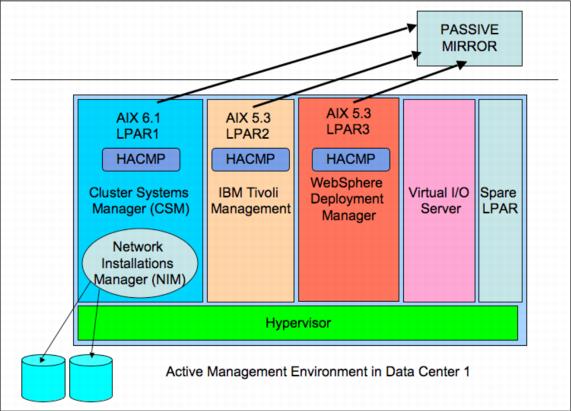
Figure 5-17 Sample WebSphere Application Server high availability e-Commerce architecture To set up the clustering and manage the environment, a systems management and WebSphere Deployment Manager environment is also required. This can be configured in a number of ways, with mirrors within a data center and mirrors across data centers, but one technique is to use a System p 520 or 550 type machine and split it into partitions for all of the management software. Management software tends to be passive rather than active from the perspective of the online transactions, and so does not need to support large loads. Centralizing the management software onto a single machine also lends itself to supporting scheduled upgrades where a failover of the entire environment is forced to the passive DR machine, and the formerly active machine is upgraded for all management software. Thus, there is a passive machine sitting in one data center that is failed over to from the primary management partitions using HACMP in each of the management partitions. This active-passive arrangement for the management environments does not affect the active-active nature of the transactional environment. As shown in Figure 5-18, note the use of a spare partition on this environment to support upgrades of the operating system and any one of the management packages by cloning the original and upgrading it before setting it up to take over the original function. This minimizes risk in upgrades because the original is left in place until the new environment is proven, with only physical resources moved between the partitions to recover.
Figure 5-18 Active Management Environment |

