On Demand Router
- Overview
- Architecture
Classification
Class-based queuing of work
Autonomic request flow manager
Load Balancing- Topology
Classic topology
Reformed topology
Clustering
Templates
Multi-cell environment
Creation
Create using the Administrative Console
Create using a wsadmin script
Change the configuration
Settings
Proxy plug-in generation
Plug-in config change script
Use scp to copy the plug-in file
Caching
Configuration of custom error pages
Logging and tracing
Deleting- Autonomic request flow manager
Configure the ARFM- Application placement controller
Configure the application placement controller
Configure the APC runtime configuration with scripting
Configure the APC configuration with scripting
Logging and tracing the application placement controller- Dynamic Workload Manager
Web server configuration
Overview
The On Demand Router (ODR) is a component located in front of a WebSphere XD environment that represents an entry point into the application server environment. The ODR is responsible for orchestrating the queuing and dispatching of requests in accordance with our service policy. Several factors are considered, including the processing capacity of a node group, performance goals, business importance, and load balancing.The ODR logically replaces and extends the functionality of the WebSphere Web server plug-in. Since the ODR is derived from the IBM WebSphere Network Deployment V6.0.2 proxy server, it provides the standard functionality of a HTTP/1.0 and HTTP/1.1 compliant proxy server with added on demand features:
- Request classification and prioritization
- Request queuing
- Routing and load balancing
- Weighted least outstanding requests dispatching using dynamic weights
- Dynamic routing table updates with multiple WebSphere backend cells
- HTTP session affinity
- SSL ID affinity
- WebSphere Partitioning Facility partition affinity
Because the ODR is the entry point into the application server environment you should make the ODR highly available by having more than one.
ODRs run the autonomic request flow manager (ARFM), which performs the request flow prioritization function. There can be multiple ODRs, and each request goes through only one ODR, but it could be any one of them. The request flows are managed to achieve the best balanced performance results, considering the configured service policies and the offered load.
The ODR is aware of its environment because of a component called an on demand configuration (ODC). The ODC automatically tries to get information about all the WebSphere XD application servers and applications that are deployed in the cell. The ODC dynamically configures the routing rules at run time to allow the ODR to accurately route HTTP requests to those application servers. After creation, an ODR is able to route HTTP requests to WebSphere XD nodes and, with some additional configuration, can also route work to non-WebSphere XD servers or end points. The ODR, like the Web server plug-in for WAS, uses session affinity for routing work requests. After a session is established on a server, later work requests for the same session go to the original server, maximizing cache usage and reducing queries to back-end resources.
The ODR provides routing of HTTP(S) traffic to:
- Dynamic clusters
- Static clusters
- Generic server clusters
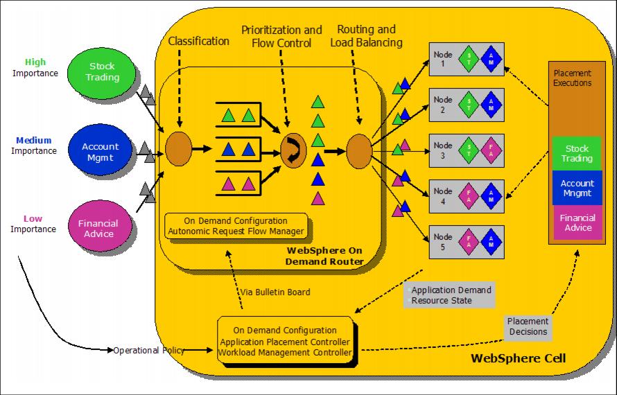
On demand router architecture overview
The ODR architecture is shown below. As we can see, there are several requests arriving for three different applications with three different importances. When the requests arrive, first the ODR classifies them. In a second step, they are prioritized. Third, the routing and load balancing component delivers these requests to the appropriate servers.
Requests with a higher importance are processed faster than those with a lower importance. The importance is configured through service policies.
Classification
One of the roles of the ODR is to accept raw requests of the incoming wire and proxy those requests to an WebSphere XD backend in an intelligent manner Requests are classified into a finite set of request types or transaction classes.
Class-based queuing of work
Once a request has been mapped to a transaction class, it is linked to that transaction class's service class. The request is then placed into the queue that corresponds to its service class; each service class is assigned a separate queue. If queues reach a (configurable) maximum length, subsequent requests will result in a message returned to the client indicating that the server is too busy to process the incoming request.
Autonomic request flow manager
The autonomic request flow manager (ARFM) in the ODR manages the flow of requests from the ODR queues to the backend nodes. When demand is low compared to the available computing capacity requests arriving in the queues are immediately sent to the backend nodes for execution. However, when the flow controller determines that computing capacity of the backend nodes is fully utilized, requests begin to wait in the ODR queues. As requests complete their execution on the backend node, the flow controller selects requests from each queue for execution on the backend nodes. The flow controller dispatches requests from queues according to a weighted least outstanding requests scheduling algorithm. The ARFM occasionally adjusts the dispatching weights of each queue to achieve business goals, based on measurements of arrival rates and service times.
Routing and load balancing
The ARFM decides when requests are executed while the routing component decides where requests are executed. Because a given request may be executed by one of several servers in the same cluster, the routing component selects a server according to affinity, or according to the number of outstanding requests and weight of each server. The ODR maintains a table of servers where it delivers work. In this table, each server has a weight assigned corresponding to the relative number of outstanding requests permitted to that server. Because requests may be destined for a dynamic cluster, the ODR keeps track of the dynamic changes in the node group. The dynamic workload manager (DWLM) periodically adjusts the load balancing weights.
The ODR can use routing policies and deliver requests according to these.
Topology
For a production environment, a minimum of two ODRs is recommended. Otherwise, the ODR would be a single point of failure (SPOF).
The ODR can either complement or replace the Web server plug-in. All requests are forwarded to the ODR(s). Therefore, when using the ODR it is possible to have a topology without Web servers in the DMZ.
Classic topology
The classic topology avoids the additional expense of a proxy server in the DMZ. The disadvantages are:
- An additional network hop is introduced for the ODRs.
- Does not support scale-out features (prioritization, intelligent routing) to other applications running on our HTTP servers in the DMZ.
Reformed topology
The advantages of using a reformed topology include full support of scale-out features, fewer network hops, and elimination of the requirement for configuring the Web server plug-in.
Disadvantages are that it might not work if we are using a third-party security proxy and that it requires a proxy in the DMZ.
The proxy server is necessary to maintain the integrity of the DMZ security. There are three fundamental principles of a DMZ that are applied here:
- Inbound network traffic from outside must be terminated in the DMZ. A network transparent load balancer, such as Network Dispatcher, does not meet that requirement alone.
- The type of traffic and number of open ports from the DMZ to the intranet must be limited.
- Components running in the DMZ must be hardened and follow the principle of least function and low complexity.
For more information, see Exploring new network topologies made possible by WebSphere XD and the On Demand Router
The ODR should not be placed in the DMZ. The ODR is a complex java application which frequently communicates with all application servers and nodes. This communication includes, for example, exchange of utilization and health status information.
Among other tasks, the ODR is calculating the load balancing weights for each application based on this information. If the ODR would be placed within the DMZ, the firewall would need a number of openings, which conflicts with the principles of a DMZ.
ODR clustering
To avoid a single point of failure, configure more than one ODR in the production environment.
In order to cluster multiple ODRs we don't need any additional configuration. But there is also no special clustering support which means that we have to configure each ODR separately.
ODR templates
We can use a template to make the task of configuring all our ODRs identically easier. In other words, we need to create one ODR, configure it as needed for our environment, then create a template based on that ODR. All other ODRs are then created using this template rather than the WebSphere default ODR template (odr).
To create an ODR template, go to...
Servers | Demand Routers | Templates | NewWe then have to select an existing ODR from which the template should be created. After selecting the previously configured ODR, click OK. In the upcoming panel we can enter the template name and a description. Click OK once again, then save and synchronize with nodes.
All On Demand Routers have to be configured identically.
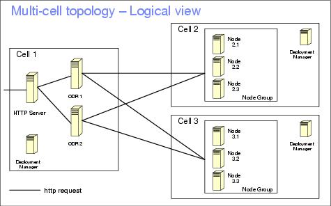
Multi-cell environment
With IBM WebSphere XD V6.0 it is possible to combine multiple WebSphere XD cells and serve them with a common set of ODRs. The ODR's get configuration information automatically from all cells.
In order to route to multiple cells, the ODR's cell must be configured to allow cross cell communication. The crossCellCGBCfg command is provided for us to perform the configuration.
Things to consider regarding multi-cell topologies:
- Applications' context roots must be unique across cells.
- You must configure core group bridges between the cells.
On demand router creation
When we create an ODR, we are actually creating a custom application profile. The only prerequisite is that we have federated the node that will host the ODR into an IBM WebSphere XD V6.0 cell.
There are two ways to create an ODR:
- Using the Administrative Console
- Using a wsadmin script
Verify that all ODR configurations are identical. Therefore, when we plan to have more than one ODR we should create them one after the other to remember configuration settings.
There is no synchronization between ODR configurations. If we change a property on one ODR, we must change it manually on other ODRs.
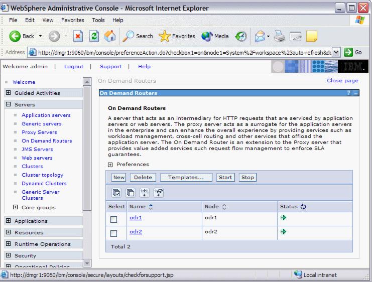
Create an ODR using the Administrative Console
In order to create an ODR, from the Administrative Console...
- Go to...
Servers | On Demand Routers | New | nodename- Provide a name for the ODR server (for example: odr1).
- Click Next.
- Select to Generate Unique HTTP Ports and click Next.
- Review the summary and click Finish.
- Save the configuration and synchronize the nodes.
After we have created the odr we can now change the configuration.
Create an ODR using a wsadmin script
We can create the ODR using a wsadmin script.
The createodr.jacl script is located on the Deployment Manager node in the $WASHOME/bin directory. Use the script as follows:
./wsadmin.sh -f createodr.jacl ODRNodeThis command creates an ODR with odr as the servername on node ODRNode. We cannot change the default server name (odr) unless you change the script itself.
When you want to create an ODR server with a different name than the default of odr, we need to change the createodr.jacl script. Create a backup copy of the original script.
You must make these changes:
After running this script we can then change the configuration of the odr using the Administrative Console.
- Change the odr name in line 32:
set serverName "odr"- Change the odr name also in line 117. Do not change the setting for templateName!
set server [$AdminTask createOnDemandRouter $nodeName {-name odr -templateName odr}]
Change the configuration of On Demand Routers
To change an ODR configuration, log on to the Administrative Console and go to...
Servers | On Demand Routers
Click an ODR name to change its configuration.
Expanding the On Demand Router Properties provides us with the following menu items:
- On Demand Router settings
- Static cache rules
- On Demand Router transports
- On Demand Router Cache instance config
- Generic Server Cluster Routing Policies
- Generic Server Cluster Service Policies
On Demand Router settings
On the ODR settings page we can configure basic ODR settings, including:
- Content Server Connection
The Content Server Connection pane allows us to configure SSL secured connections. First create a new SSL alias under...
Security | SSL | New JSSE repertoire- Caching
- Exclusions
We can disable certain HTTP request methods using the Exclusions pane. If a requested HTTP method matches any of the excluded methods, the ODR rejects the request with a METHOD DISALLOWED error.
- Logging
By enabling access logging we can log all traffic that goes through the ODR. This is not a trace logging for errors that occur within the ODR!
- Proxy Plug-in Configuration Policy
The ODR is an enhancement of the WebSphere Network Deployment proxy server. There are a lot of identical features between the ODR and the proxy server.
Proxy plug-in generation
When using the classic topology with a Web server in the DMZ, we must generate a special Web server plug-in. This special plug-in routes incoming traffic to the ODRs instead of directly to the application servers - which is what happens when we use the default Web server plug-in. This special plug-in replaces the plug-in that is usually automatically generated for the Web servers. The name of this plug-in file is identical to the normal Web server plug-in file, which is plugin-cfg.xml.
The new plugin-cfg.xml is automatically created by the ODR every time a configuration change happens that affects the file, such as adding, deleting, modifying applications or when the number of ODRs changes.
The ODR that is configured to generate plugin-cfg.xml files must be running for dynamic updates to occur. Furthermore, an application must be started for a corresponding update to the plugin-cfg.xml to be made.
The file is generated in...
$WASHOME/profiles/ODR_Node/etc/...and must be copied to the Web servers afterwards.
First, we must decide which ODR generates a plugin-cfg.xml file. This depends on how many unique plugin-cfg.xml files must be generated. Each ODR can generate a plugin-cfg.xml file and it depends on our environment which scope we need.
The Proxy Plug-in Configuration Policy is used by the ODR to determine how to generate a plugin-cfg.xml file. To configure this setting, go to...
Servers | On Demand Routers | ODR_name | On Demand Router settingsOn the Configuration panel scroll down to the Proxy Plugin Configuration Policy pane.
Select one of the following scopes:
All Generated plugin-cfg.xml file includes all ODRs in the environment. Cell Plug-in file includes all ODRs in the same cell. Node Plug-in file includes all ODRs on the same node. Server Plug-in file includes only a single ODR (itself). None Disables generation of the plugin-cfg.xml file. If all Web server plug-ins route to all ODRs, choose any single ODR to generate a plugin-cfg.xml file and select All as the scope. If we want to tie particular Web servers to particular ODRs, select the appropriate scope, such as Cell or Node. If we want each ODR to be fronted by a single Web server, select Server and configure each ODR to generate a plugin-cfg.xml file.
We then have the option to manually copy generated plug-in files to the appropriate Web servers or to use an automated plug-in configuration change script as described below.
Plug-in config change script
The second field in the Proxy Plugin Configuration Policy pane allows us to specify a Plug-in config change script. The ODR will run this script every time it generates a new plugin-cfg.xml. We must specify the path and name of the script here, for example:
    /opt/IBM /WebSphere/AppServer/profiles/odr1/bin/copy_plugin.sh

    #!/bin/sh
    scp /opt/IBM/WebSphere/AppServer/profiles/odr1/etc/plugin-cfg.xml web2:/usr/IBM/WebSphere/Plugins/config/web2
    scp /opt/IBM/WebSphere/AppServer/profiles/odr1/etc/plugin-cfg.xml web1:/usr/IBM/WebSphere/Plugins/config/web1
    exit 0
The server names in this example (odr1, web1 and web2) have to be replaced by our actual ODR and Web server names.
The ODR's SystemOut.log does not write any log entry if the copy was successful (the script returns exit code 0 which means that there was no error when executing the script). For testing purposes, it could be helpful to set the exit code manually to 1 so that we have a log entry and thus the prove that the script was executed successfully.
Using scp to copy the plug-in file
Use the scp command to copy the plugin-cfg.xml file. If we do not have an identity file under ~/.ssh/identity we need to specify where the ssh key is located with the -i filename parameter.
The identity has to be in the.ssh directory of the home directory of the WebSphere XD user for example, /root/.ssh.
To generate the server ssh key use the ssh-keygen command:
ssh-keygen -t rsa -f ~/.ssh/identity -C "ODR servername"Leave the passphrase empty, otherwise the copy plugin script will not work. Be aware that this is a security risk because if someone is root on the ODR server, he can get root rights on the Web servers as well. A possible workaround is to copy the files as a different, non-root user, using a different identity file.
Our public key is located in this file:
~/.ssh/identity.pubAfter creating the ssh-key we must insert our public key in the authorized_keys file on the Web servers:
~/.ssh/authorized_keys
Caching in the ODR
The ODR in IBM WebSphere XD V6.0 is derived from the IBM WebSphere Network Deployment V6.0.2 proxy server and inherits its caching capabilities. The ODR caches according to the HTTP 1.1 specification (RFC 2616) heuristics (static caching) and also according to WAS dynamic caching heuristics (dynamic caching).
Static caching refers to the proxy's ability to cache content based on the cache heuristics defined in RFC 2616. An example of such heuristics are the Cache-Control header and the Expires header.
Dynamic caching refers to the proxy's ability to cache content based on the WAS V6.0.2 and above dynamic caching heuristics. An example of these heuristics would be setting the time to live of a servlet in the cachespec.xml of an application.
Static caching is enabled by default while dynamic caching is disabled by default. Dynamic caching also requires additional setup on the application server. See the InfoCenter or Chapter 10., "Dynamic caching" of the redbook IBM WebSphere V6 Scalability and Performance Handbook, SG24-6392 for details.
For more information about caching see the InfoCenter article Caching content in the proxy server.
Configuration of custom error pages
The ODR can send out custom error pages instead of normal HTTP error pages. This allows us to present a more friendly and personalized error message than the default, plain one to our Web site users should an error occur.
These error pages are part of an application that runs on the ODRs. Because this a full J2EE application, the opportunity of still helping our users even though there is an error is maximized.
The custom error pages are extremely helpful for lazy application start. When the application is not yet started, the user gets a HTTP error 503 - Server unavailable message. As an example, we could customize this error page so it automatically retries the server every 30 seconds and explain the reason why the server is not running to the user at the same time.
As a starting point, we can use the default error-handling application that comes with WebSphere XD called HTTPErrorHandler.ear, which is located in the $WASHOME/installableApps directory. We can create our own error handling application based on this one. To use this application, follow these steps:
- Install the application onto all ODRs in our environment. That means, at the Map modules to servers installation step, select all ODRs and the ErrorPageApp module and click Apply to map the application to the ODRs. We do not need to configure a cluster that spans the ODRs for this setup.
- After we have installed this application, we can test it. For example:
http://odr1/ErrorPageApp/ErrorPageA white page with a blue bar at the top appears. We do not need to start the application. In fact, we cannot start the application at all.
- The next task is to configure the On Demand Routers.
To do so, go into the Administrative Console and click...
Servers | On Demand Routers | ODR_name | On Demand Router Properties | On Demand Router settingsScroll down to the Custom Error Page Policy section and enter the following:
- Into the Error page generation application URI field:
- Optionally check the Handle remote errors box.
If we enable the handling of remote errors, all error messages from the remote application server will be customized. If we do not want this, uncheck it.
- In the HTTP status codes that are to be recognized as errors field enter any specific HTTP response codes that should be handled by our error page application. We can use X as a wildcard character to denote code ranges. For example, type 4XX to denote all status codes between 400 and 499. Verify that we have each error code (range) on a separate line. For example:
4XX
5XXUnlike the statement in the InfoCenter, error codes must not be comma separated. There must be one error code per line.
- Click OK, save our changes and synchronize with all nodes. The ODRs don't need to be restarted for these changes to become active.
This information is stored in $WASHOME/profiles/ ODR_name/config/cells/cell_name/nodes/ODR_name/
servers/ODR_name/proxy-settings.xml:<errorPagePolicy xmi:id="CustomErrorPagePolicy_1129309186146" errorPageAppURI="/ErrorPageApp/ErrorPage" handleRemoteErrors="true"> <statusCodes>4XX</statusCodes> <statusCodes>5XX</statusCodes> </errorPagePolicy>
Logging and tracing ODRs
We can activate logging and tracing for the ODR with the following log detail level:
com.ibm.ws.proxy.*=all This gives we information about the routing, communication errors, and response codes. com.ibm.ws.odc.*=all This will trace all configuration updates to each node. The on demand configuration service (odc) is the communication protocol that the ODR uses to communicate with the nodes. Information on clusters (static and dynamic), service policies, work classes, transaction classes, and dynamic workload management is provided to the ODR via odc. The log and trace files grow very fast. Set the log size to a big enough value.
For further infomation about how to activate logging and tracing in WebSphere XD see section 9.4, "Traces" in WAS V6 System Management and Configuration Handbook, SG24-6451.
Deleting an On Demand Router
There are two ways to delete an ODR:
- Deleting an ODR through the Administrative Console.
In the Administrative Console go to...
Servers | On Demand Routers | odr_name Delete- Deleting an ODR using a wsadmin script.
The wsadmin script is located in the $WASHOME/bin directory on the Deployment Manager node.
This script will delete the On Demand Router named odr on node ODRNode. We cannot change the servername unless we change the script itself.
Autonomic request flow manager
The autonomic request flow manager (ARFM) continuously monitors the performance of each service class and adjusts the queue dispatching weights in the ODR. The ARFM modifies the weights of queues to align flow control with business goals. When adjusting the dispatching weight, ARFM includes:
- The amount of computing resources that each class of request consumes
- The size and placement of each dynamic cluster
- The computing power of each node in the node group
- The performance goals and business importance of each service class
The features of the autonomic request flow manager include:
- Classifying incoming requests. The work is then queued based on the classification (service policies).
- Limiting the number of requests on a given server to protect servers from being overloaded.
- Dispatching work out of the queues based on work classes.
- Dynamically adjusting weights to achieve response time goals for different classes of requests and to respond to varying load conditions and request surges.
The ARFM consists of three components:
Gateway The ARFM gateway runs on the ODRs and there is one gateway for each ODR=Deployment Target pair. The gateway is practically a request queue manager and it handles all queues for a specific deployment target. Controller The ARFM controller monitors the request flow. It receives all information from every gateway. There is one controller per cell. The controller sends information about the amount of traffic and how well service goals are meet to the application placement controller (APC). Work profiler The work profiler monitors the CPU utilization of each node and sends this information also to the APC. There is one work profiler for each cell.
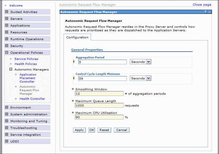
Configure the ARFM
We can adjust the settings of the autonomic request flow manager. The following settings can be changed:
Aggregation period Each ARFM gateway broadcasts aggregated statistics periodically, and this parameter specifies the period. The statistics reported by the gateways support:
- The runtime charting in the WebSphere XD Administrative Console.
- The operation of the ARFM controllers.
- The operation of the APC.
The aggregation period is the time period the gateway collects the data on the nodes. The more data it collects the more accurate the runtime statistics are. But if the value is to high, the ARFM cannot response to a sudden increase of load. A value between 5 and 20 seconds is recommended. The default is 5 seconds.
Control cycle length minimum How often the ARFM controller is activated. Controller activation is the process of evaluating inputs and producing new control settings as a result of the input that is received. The default is 59 seconds. Smoothing window Defines how sensitive the ARFM controller reaction is to the incoming gateway statistics, by allowing a concatenation of gateway statistics. The smoothing window controls the number of reports that are combined. The default is 12 reports. Maximum queue length Bind the length of each ARFM queue to a maximum number of requests that might be held in queue. ARFM has a separate queue for each combination of On Demand Routers, node groups, service classes, and deployment targets. When a request arrives and the queue is full, the request is rejected. The default is 1000. Maximum CPU utilization The ARFM provides overload protection, in addition to its prioritization capabilities. An ARFM queues requests in its gateways to avoid overloading the application servers. The maximum CPU utilization parameter tells ARFM how heavily to load the servers. The default is 90%.
For more infomation about this topic see the InfoCenter article Configure the autonomic request flow manager.
Application placement controller
The application placement controller (APC) decides where applications run and how many server instances are started for each application.
The APC receives information from the autonomic request flow manager and together with the performance data and the configured service policies and service goals it computes the optimal allocation of available resources to running applications. The APC determines the available capacity of each node. It is aware of all processes running on each node including non-WebSphere processes. It takes CPU and memory usage into account and finds the application that fits this node best.
The APC increases or decreases the number of started application servers. It does not deploy applications on demand. When a new application is deployed into a dynamic cluster, this application is directly installed on every node in the node group. Later on the APC decides when to start which application depending on the service policies and the current load. Otherwise, it would take to much time to continuously install and uninstall applications in the node group.
Information about newly started or stopped application servers is also given back to the ODR. The ODR reconfigures the routing rules according to these changes.
There is only one APC per cell. We can discern where the APC is running, either by looking at the Runtime Topology in the Administrative Console or but using a wsadmin script
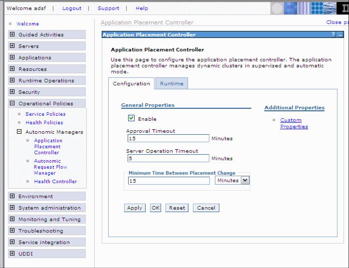
Configure the APC
The APC is configured in the Administrative Console under...
Operational Policies | Autonomic Managers | Application Placement ControllerThere are two configurations that we can change:
- Persistent configuration
Changes to the persistent configuration will not take immediate effect - they require the APC to be disabled and enabled again.
- Runtime configuration
Changes that we perform on the runtime configuration tab take immediate effect but are not made permanent except when checking the Save To Repository box.
We can change the following configuration settings.
- Enable or deselect to disable the APC.
- Approval Timeout for the supervised mode of the dynamic cluster. Possible values are 1 to 60 minutes.
- Server Operation Timeout is the amount of time after a start or stop operation is considered a failure. This should be set to whatever is the predicted worst case time to start or stop a server. Possible values are 1 to 60 minutes.
- Minimum Time between Placement Change is the time the APC should wait before initiating a change. Acceptable values range from 1 minute to 24 hours.
The time between placement changes should depend on how long an application server start takes. Best practise for this value is to define it to be at least 20 to 30 times larger than the time necessary to start the server.
For more infomation about APC configuration see the InfoCenter article Monitoring and tuning the application placement controller
Configure the APC runtime configuration with scripting
To change the runtime configuration we can use the JACL script PlacementControllerProcs.jacl which comes with WebSphere XD. For permanent changes we have to use the xd_APCconfig.jacl script located in $WASHOME/bin. Here are some examples on how to use the script:
Usage of the script, its commands and parameters can be obtained using:
./wsadmin.sh -profile PlacementControllerProcs.jacl -c "help"
We can change the Approval Timeout using this command:
./wsadmin.sh -profile PlacementControllerProcs.jacl -c "setApprovalTimeOut 12"
To retrieve the current node where the APC is running, enter:
./wsadmin.sh -profile PlacementControllerProcs.jacl -c "getNodeName"
Available procedures for this script.
Name of procedure Description enable Enable the APC. disable Disable the APC. disableNode node Make the specified node unmanaged by the APC. disableNode node_group_name node Make the node unmanaged as a member of the node group. findBestNodeToDisable Find the best node to disable. isNodeInUse node Check if a node is still in use after it is in maintenance mode. enableNode node_name Make the specified node managed by the APC. enableDynamicCluster node_group_name dynamic_cluster_name Set the specified dynamic cluster to run automatically. enableDynamicCluster dynamic_cluster_name Set the specified dynamic cluster to run automatically. disableDynamicCluster node_group_name dynamic_cluster_name Set the specified dynamic cluster to run manually. disableDynamicCluster dynamic_cluster_name Set the specified dynamic cluster to run manually. isEnabled Return if the APC is enabled. getNodeName Display the node on which the APC is running. setMinTimeBetweenPlacementChange time Set the minimum time, in minutes, between two consecutive placement changes. setServerOperationTimeOut timeout Set the timeout, in minutes, after which the start or stop operation that is performed on the server is considered a failure if not completed. setApprovalTimeOut approval_timeout Set the amount of time, in minutes, to wait for the administrator approval when operating in supervised mode before considering the task denied. getMinTimeBetweenPlacementChange Return the minimum time between two consecutive placement changes. getServerOperationTimeOut Return the amount of time after which the start and stop operation that is performed on the server is considered a failure, if not completed. getApprovalTimeOut Return the amount of time to wait for an administrator to approve a task when running in supervised mode. recomputePlacement Trigger the APC to compute its optimization and perform any necessary placement changes.
Configure the APC configuration with scripting
In order to make persistent changes to the APC, we need to use the xd_APCconfig.jacl script. The changes we make here will not be effective immediately. They become active when the APC is disabled and enabled again.
For the script usage type:
./wsadmin.sh -profile xd_APCconfig.jacl -c "help"
xd_APCconfig.jacl script
/usr/IBM /WebSphere/AppServer/bin #./wsadmin.sh -profile xd_APCconfig.jacl
WASX7209I: Connected to process "dmgr" on node dmgr1 using SOAP connector;
The type of process is: DeploymentManager
WASX7029I: For help, enter: "$Help help"

wsadmin>$AdminConfig show [$AdminConfig getid "/AppPlacementController:/"]
{approvalTimeOut 10}
{enable true}
{minTimeBetweenPlacementChange 15}
{minTimeBetweenPlacementChangeUnits 2}
{properties {}}
{serverOperationTimeOut 5}

wsadmin>setAPCAttribute approvalTimeOut 15

wsadmin>$AdminConfig show [$AdminConfig getid "/AppPlacementController:/"]
{approvalTimeOut 15}
{enable true}
{minTimeBetweenPlacementChange 15}
{minTimeBetweenPlacementChangeUnits 2}
{properties {}}
{serverOperationTimeOut 5}
For more usage examples see the InfoCenter article Change application placement configurations with scripting.
Logging and tracing the application placement controller
We can activate logging and tracing for the APC with this setting:
com.ibm.ws.xd.placement*=all=enabledWe can either change the trace level through the Administrative Console or using a wsadmin script.
Additional infomation about tracing the APC is provided in the InfoCenter article Trace settings for autonomic request flow manager and application placement.
For infomation about how to activate logging and tracing in WebSphere XD see section 9.4, "Traces" in WAS V6 System Management and Configuration Handbook, SG24-6451.
Dynamic Workload Manager
The autonomic request flow manager (ARFM) classifies and prioritizes requests to application servers based on the demand and policies. The dynamic workload manager (DWLM) then distributes the requests among the nodes in a node group to balance the work.
It sets the load balancing weights for application servers dynamically to stay current with the business goals. The weights are then used by the router in the ODR to distribute the workload accordingly. This autonomic manager continuously monitors the response time and resource utilization of each server and uses feedback control techniques that change the dispatching weights to achieve balance across clusters and nodes.
DWLM is also able to dynamically update the application status as the application placement controller may make modifications to a running application infrastructure.
DWLM is enabled by default. It can be enabled or disabled through the Administrative Console under...
Servers | Dynamic Clusters | cluster_name | Dynamic WLM
Web server configuration
If our Web servers are running on managed nodes (that is, a Node Agent is present on the Web server system) or if we are using the special case of the IBM HTTP Server V6.0 running on an unmanaged node, which supports the same functions as when using a managed node, then we must disable the automatic generation and propagation of the Web server plug-in. This makes sure that we use the ODRs plug-in file rather than the Web server plug-in file.
The reason for this is that the Web servers automatically update their plugin-cfg.xml file when plug-in related configurations happen in the environment. This has to be disabled because the plugin-cfg.xml that is generated on the Web servers will direct requests directly to the application server environment rather than to the ODRs.
To disable automatic generation and propagation of the Web server plug-in...
Go to...
Servers | Web servers | Web_server_name | Plug-in properties- Deselect Automatically generate the plug-in configuration file check box.
- Deselect Automatically propagate plugin configuration file.
- Click OK and save the configuration.