Designing distributed queue manager networks
IBM MQ sends and receives data between applications, and over networks using Queue Managers and Channels. Network planning involves defining requirements to create a framework for connecting these systems over a network.
Channels can be created between your system and any other system with which you need to have communications. Multi-hop channels can be created to connect to systems where we have no direct connections. The message channel connections described in the scenarios are shown as a network diagram in Figure 1.
Channel and transmission queue names
Transmission queues can be given any name. But to avoid confusion, we can give them the same names as the destination queue manager names, or queue manager alias names, as appropriate. This associates the transmission queue with the route they use, giving a clear overview of parallel routes created through intermediate (multi-hopped) queue managers.
It is not so clear-cut for channel names. The channel names in Figure 1 for QM2, for example, must be different for incoming and outgoing channels. All channel names can still contain their transmission queue names, but they must be qualified to make them unique.
For example, at QM2, there is a QM3 channel coming from QM1, and a QM3 channel going to QM3. To make the names unique, the first one might be named QM3_from_QM1, and the second might be named QM3_from_QM2. In this way, the channel names show the transmission queue name in the first part of the name. The direction and adjacent queue manager name are shown in the second part of the name.
A table of suggested channel names for Figure 1 is given in Table 1.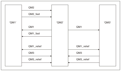
| Route name | Queue managers hosting channel | Transmission queue name | Suggested channel name |
|---|---|---|---|
| QM1 | QM1 & QM2 | QM1 (at QM2) | QM1.from.QM2 |
| QM1 | QM2 & QM3 | QM1 (at QM3) | QM1.from.QM3 |
| QM1_fast | QM1 & QM2 | QM1_fast (at QM2) | QM1_fast.from.QM2 |
| QM1_relief | QM1 & QM2 | QM1_relief (at QM2) | QM1_relief.from.QM2 |
| QM1_relief | QM2 & QM3 | QM1_relief (at QM3) | QM1_relief.from.QM3 |
| QM2 | QM1 & QM2 | QM2 (at QM1) | QM2.from.QM1 |
| QM2_fast | QM1 & QM2 | QM2_fast (at QM1) | QM2_fast.from.QM1 |
| QM3 | QM1 & QM2 | QM3 (at QM1) | QM3.from.QM1 |
| QM3 | QM2 & QM3 | QM3 (at QM2) | QM3.from.QM2 |
| QM3_relief | QM1 & QM2 | QM3_relief (at QM1) | QM3_relief.from.QM1 |
| QM3_relief | QM2 & QM3 | QM3_relief (at QM2) | QM3_relief.from.QM2 |
- On IBM MQ for z/OS®, queue manager names are limited to four characters.
- Name all the channels in your network uniquely. As shown in Table 1, including the source and target queue manager names in the channel name is a good way to do so.
Network planner
Creating a network assumes that there is another, higher level function of network planner whose plans are implemented by the other members of the team.
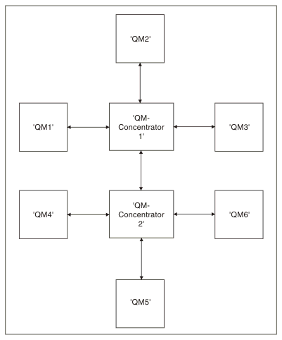
For widely used applications, it is more economical to think in terms of local access sites for the concentration of message traffic, using wide-band links between the local access sites, as shown in Figure 2.
In this example there are two main systems and a number of satellite systems. Tthe actual configuration would depend on business considerations. There are two concentrator queue managers located at convenient centers. Each QM-concentrator has message channels to the local queue managers:- QM-concentrator 1 has message channels to each of the three local queue managers, QM1, QM2, and QM3. The applications using these queue managers can communicate with each other through the QM-concentrators.
- QM-concentrator 2 has message channels to each of the three local queue managers, QM4, QM5, and QM6. The applications using these queue managers can communicate with each other through the QM-concentrators.
- The QM-concentrators have message channels between themselves thus allowing any application at a queue manager to exchange messages with any other application at another queue manager.