Enterprise Content Management
WebSphere Adapter for Enterprise Content Management documentation
With WebSphere Adapter for Enterprise Content Management, you can create integrated processes that include the exchange of information with a CMIS server, without special coding.
Overview of WebSphere Adapter for Enterprise Content Management
With WebSphere Adapter for Enterprise Content Management, you can create integrated processes that include the exchange of information with a Content Management Repository, without special coding. The adapter is built with the open source specification for content repositories called Content Management Interoperability Services (CMIS).
Use the adapter, an application component (the program or piece of code that perform a specific business function) can send requests to a Content Management Repository, for example, to create a new Document or a Folder in a Content Management Repository or update an existing document Content Management Repository in a Content Management Repository software or receive event notifications from the server, for example, to be notified when a new Document or Folder is created, deleted. Since the adapter has been built on the Content Management Interoperability Services (CMIS) specification, it creates a standard interface to the data access interface on any Content Management Repository so the application component does not have to understand the lower-level details such as the implementation of the application or the data structures.
WebSphere Adapter for Enterprise Content Management complies with the Java™ Platform, Enterprise Edition (JEE) Connector Architecture (JCA) version 1.5. JCA 1.5 standardizes the way application components, application servers, and enterprise information systems which implement the CMIS specification, interact with each other. WebSphere Adapter for Enterprise Content Management makes it possible for JCA-compliant application servers to connect to and interact with a Content Management Repository. Application components running on the JCA-compliant server can then communicate with the Content Management Repository in a standard way using business objects.
The following example assumes that you are setting up an adapter using IBM Integration Designer and deploying the module that includes the adapter to IBM Business Process Manager or WebSphere Enterprise Service Bus.
In this example, an organization uses FileNet Content Engine version 4.6.0 as the Content Management (CM) tool for most of its business operations. Employee data of the organization is stored securely in the Content Engine. The Employee data can be modified, retrieved, or created afresh. An application component might be able to use this function as part of an overall business process. For example, information about new hires in the organization can be stored in the Content Engine without specific coding. User information can also be updated to reflect promotions.
With the WebSphere Adapter for Enterprise Content Management, you can automatically generate an interface to the data interface of FileNet Content Engine to hide the lower-level details of the function. Depending on how you want to use the adapter, you can embed it with the deployed module, or install the adapter as a stand-alone component, to be used by more than one application. The adapter is deployed to IBM Business Process Manager or WebSphere Enterprise Service Bus. The application component directly interacts with the adapter, and not with FileNet Content Engine.
The adapter module, which you generate with the external service wizard of IBM Integration Designer, uses a standard interface and standard business objects. The adapter takes the standard business object sent by the application component and starts the appropriate function on the Content Engine. The adapter then returns a standard business object to the application component. The application component does not have to interact directly with the CMIS services; it is the Adapter for Enterprise Content Management that calls the service and returns the results.
To create data for a new employee, the application component will send a standard business object with the information of the new employee to the Adapter for Enterprise Content Management. The application component will receive, in return, the results (success or failure along with the Object Identity, ID) in a standard business object format. The application component is not required to know that how the function worked or how the data was structured. The adapter then interacts with the actual Content Management Repository system.
The WebSphere Adapter for Enterprise Content Management is designed to connect to all Content Management Repositories which implement the CMIS interface. For this release, the adapter will be connecting to FileNet Content Engine.
- Hardware and software requirements The hardware and software requirements for WebSphere Adapters are provided on the IBM Support website.
- Technical overview of WebSphere Adapter for Enterprise Content Management The adapter supports bidirectional exchange of business data between business applications and Content Management Repository systems, which implement the Content Management Interoperability Services (CMIS) v1.0 specification. The adapter provides outbound and inbound processing under the Java Platform, Enterprise Edition (JEE) Connector Architecture (JCA) and integrates with Service Component Architecture (SCA) components.
Hardware and software requirements
The hardware and software requirements for WebSphere Adapters are provided on the IBM Support website.
To view hardware and software requirements for WebSphere Adapters, see http://www.ibm.com/support/docview.wss?uid=swg27006249.
Additional information
The following links provide additional information you might need to configure and deploy your adapter:
- The compatibility matrix for WebSphere Business Integration Adapters and WebSphere Adapters identifies the supported versions of required software for your adapter. To view this document, go to the WebSphere Adapters support page: http://www.ibm.com/support/docview.wss?uid=swg27006249.
- Technotes for WebSphere Adapters provide workaround and additional information not included in the product documentation. To view the technotes for your adapter, go to the following Web page, select the name of your adapter from the Product category list, and click the search icon: http://www.ibm.com/support/search.wss?tc=SSMKUK&rs=695&rank=8&dc=DB520+D800+D900+DA900+DA800+DB560&dtm.
Technical overview of WebSphere Adapter for Enterprise Content Management
The adapter supports bidirectional exchange of business data between business applications and Content Management Repository systems, which implement the Content Management Interoperability Services (CMIS) v1.0 specification. The adapter provides outbound and inbound processing under the Java™ Platform, Enterprise Edition (JEE) Connector Architecture (JCA) and integrates with Service Component Architecture (SCA) components.
The adapter provides the means for services running on IBM Integration Designer to exchange documents with one or more Content Management Repositories. The services are contained in a module, which consists of both a project in IBM Integration Designer and a unit of deployment to IBM Business Process Manager. The module is packaged and deployed to IBM Business Process Manager as an enterprise archive (EAR) file.
What is a Content Management Repository?
A Content Management Repository is the strategies, methods and tools used to capture, manage, store, preserve, and deliver content and documents related to organizational processes. Content Management Repository tools and strategies allow the management of unstructured information an organization, wherever that information exists.
The Content Management Repository server metadata
WebSphere Adapter for Enterprise Content Management interacts with a Content Management Repository server using the following metadata constituents:
- A CMIS service endpoint identifies a CMIS server.
- A CMIS service endpoint may provide access to more than one Content Management Repositories.
- A Content Management Repository can contain Document Objects and Folder Objects, among other objects.
- A Document object represents a stand-alone information asset. Document objects are the elementary entities managed by a Content Management Repository.
- A Folder object represents a logical container for a collection of file-able objects, which include folder objects and document objects. Folder objects are used to organize file-able objects.
- Every CMIS object has an opaque and immutable Object Identity (ID), which is assigned by the repository when the object is created. An ID uniquely identifies an object within a repository regardless of the type of the object.
- Every CMIS object has a set of named, but not explicitly ordered, Properties.
- The Adapter for Enterprise Content Management is now capable of creating and deleting documents.
FileNet Content Engine caches the metadata to the length of time specified in the CMC_TIME_TO_LIVE property. To increase the frequency of cache updates and to receive the latest information from the FileNet server, specify a lower value for the CMC_TIME_TO_LIVE property by editing the WEB-INF/classes/cmis.properties file. For more information about this property, see Configure advanced IBM CMIS for FileNet Content Manager properties.
- Outbound processing The WebSphere Adapter for Enterprise Content Management supports outbound request processing. When the adapter receives a request, which is sent in the form of a business object from the module, it processes the request and returns the result as a business object. The adapter provides a standard set of outbound operations.
- Inbound processing Adapter for Enterprise Content Management supports inbound processing of events. The adapter polls the event database in the CMIS server for events at specified intervals. Each time a subscription is created or updated, the adapter tracks the process as an event. When the adapter detects an event, it requests a copy of the subscription, converts the data into a business object, and sends it to the consuming service.
- Log and Trace Analyzer The adapter creates log and trace files that can be viewed with the Log and Trace Analyzer.
Outbound processing
The WebSphere Adapter for Enterprise Content Management supports outbound request processing. When the adapter receives a request, which is sent in the form of a business object from the module, it processes the request and returns the result as a business object. The adapter provides a standard set of outbound operations.
Outbound processing begins when a module receives a business object from a service, which is called a request. When a request is received, the adapter uses the information stored in the business object and metadata from the interaction specification properties to perform an operation on the Content Management Repository.
The adapter supports the following outbound operations for Document Types:
- Create
- Delete
- Retrieve
- RetrieveProperties
- Update
- UpdateProperties
- RetrieveAll
The adapter supports the following outbound operations for Folders:
- Create
- Delete
- Retrieve
- Update
- RetrieveAll
The figure below shows how the adapter and module function together as part of an outbound service. A module created for outbound processing receives the request. The adapter determines the operation to be performed based on the information received in the metadata from the interaction specification properties. It then performs the operation on the Content Management Repository.
Figure 1. Adapter for Enterprise Content Management as part of an outbound SOA implementation

The adapter connects to the CMIS server with the repository URL, user name, and password information. After connecting to the Content Management Repository server, the adapter lists all available CMIS Repositories. In each Repository, there can be several types of Document types and Folders. Instances of these Document types and Folders are stored and managed by the Content Management Repository. The adapter lists all Document types and Folders in a Repository and allows the user to select the Document types and Folders as business object types. For each selected business object type, method binding artifacts are generated to support outbound operations.
- Outbound operations Application components use operations to perform actions such as creating instances of Document types or Folders on the Content Management Repository. The adapter provides certain outbound operations. The name of the operation typically indicates the type of action the adapter takes, such as Create or Delete.
Outbound operations
Application components use operations to perform actions such as creating instances of Document types or Folders on the Content Management Repository. The adapter provides certain outbound operations. The name of the operation typically indicates the type of action the adapter takes, such as Create or Delete.
During outbound processing, the calling component (part of SCA application) calls the adapter to connect and work with business data on the Content Management Repository. All interactions between the calling component and the server are request-response type.
- Create operation The Create operation creates a document or a folder corresponding to the selected Document type or Folders in the Content Management Repository specified content.
- Retrieve operation The Retrieve operation extracts the document content or folder properties based on the request from the SCA component. For Document types, the Retrieve operation retrieves the content and also the properties from the document. For Folders, the Retrieve operation retrieves the properties of the folder.
- RetrieveAll operation The RetrieveAll operation extracts the properties of all documents along with the Document URLs to the content of the documents or folders which match a search criteria specified in the request from the SCA component.
- Update operation The Update operation updates a document or folder properties in the CMIS server based on the request from the SCA component.
- Delete operation The Delete operation deletes a document or folder in the Content Management Repository based on the request from the SCA component.
- RetrieveProperties operation The RetrieveProperties operation extracts the properties of a document content based on the request from an SCA component.
- UpdateProperties operation The UpdateProperties operation updates the properties in a document in the CMIS server based on the request from the SCA component.
Create operation
The Create operation creates a document or a folder corresponding to the selected Document type or Folders in the Content Management Repository specified content.
Document Types
The adapter receives a request in the form of a business object to a create instance of a Document type in the CMIS Repository. The adapter processes the request and a document with a unique immutable Object Identity (ID) is created in the Content Management Repository. The content of the document is obtained from the attribute values of the requested business object.
An example of a request business object is modeled as below:
Figure 1. Structure of a request business object

Every Document Type has a set of named, but not explicitly ordered, Properties that are added in a separate business object. The name of this business object would be the Document Type in Camel-case, followed by the word Properties.
The content of the Document is handled in a separate business objecttitled DocumentContent.
LocalPath and Bytes are options for filling up the content that should go into the document. To create refer to a file in the local file system from which content is to be taken, provide the absolute file name in the LocalPath Business Object field. To provide the content as hexBinary bytes, provide the content in hexBinary form in the Bytes Business Object field.
The Bytes field takes precedence over the LocalPath field. Therefore, if you provide values for both the Bytes and the LocalPath fields, the adapter takes the value provided in the Bytes field, and continue the process.
After the document is created, the Properties business object is sent back to the calling component as a response to indicate the document was created successfully.
Figure 2. Structure of a response business object

After a successful create operation, the containment name of the document is populated in the pathSegment property. To perform other operations using the filename, reference the value of the pathSegment property in the cmisU58name property.
Folders
The adapter receives a request in the form of a business object to a create an instance of a Folder in the Content Management Repository. The adapter processes the request and a Folder with a unique immutable Object Identity (ID) is created in the Content Management Repository.
To successfully execute a request, either the Path or the Id values in the Parent child business object must be provided in the request business object. This represents the parent folder in which the new folder is created.
An example of a request business object for Folders is modeled as below:
Figure 3. Structure of a request business object for Folders
After the Folder is created, the Properties Business Object is sent back to the calling component as a response to indicate the Folder was created successfully.
Figure 4. Structure
of a response business object for Folders
During run time, if data is not entered for any of the fields, namely,
- RepositoryID, DocumentName, or TargetFolder in the case of Document Types
- Path or the ID values in the Parent child business object in the case of Folders,
a MissingDataException error is returned. This eventually manifests as a ResourceException which is returned to the calling component.
Related reference:
Retrieve operation
The Retrieve operation extracts the document content or folder properties based on the request from the SCA component. For Document types, the Retrieve operation retrieves the content and also the properties from the document. For Folders, the Retrieve operation retrieves the properties of the folder.
Document Types
The adapter receives the request to retrieve a document along with the document location. The TargetFolder and cmisU58name properties must be populated with appropriate values pointing to the document path. Alternately, the cmisU58objectId property in the request can be populated with the Object ID of the document. The adapter processes the request and extracts the content of the document from the Content Management Repository.
When both Object ID and document path are provided as input to the operation, the Object ID takes a precedence over the document path value to perform the operation.
The following figure shows the structure of a request EmailDocumentProperties business object.
Figure 1. Structure of a request business object
After the content of the document is retrieved in the form of a byte array, it is sent back as the response to the calling component. The response has the top-level business object containing the content of the document and the document properties. The attributes in the business object include information about the retrieved document.
Figure 2. Structure of a response business object
Folders
The adapter receives a request in the form of a business object to retrieve properties of a Folder in the CMIS Repository. The field cmisU58path properties must be populated with appropriate values pointing to the folder.
The path must be the absolute path to the folder starting from the root. Alternately, the cmisU58objectId property in the request can be populated with the Object ID of the folder. The adapter processes the request and extracts the properties of the folder from the Content Management Repository.
An example of a request business object for Folders is modeled as below:
Figure 3. Structure of a request business object for Folders
After the Folder is retrieved, the Properties business object is sent back to the calling component as a response.
Figure 4. Structure of a response business object for Folders
When there is a processing error, the Retrieve operation might return the InvalidRequestFault or the DocumentNotFoundFault fault. For more information about these business faults, see Fault business objects.
Related reference:
RetrieveAll operation
The RetrieveAll operation extracts the properties of all documents along with the Document URLs to the content of the documents or folders which match a search criteria specified in the request from the SCA component.
Document Types
The adapter receives the request to retrieve document which matches a specified search criteria. The search query resembles a standard SQL statement and contains a Select Clause and a Where Clause. The From Clause is a business object level annotation of the RetrieveCriteria Business Object. The SelectClause and WhereClause can be specified in the request business object but the FromClause is fixed.
For example:
Figure 1. Example
 In this example,
- (1) indicates the SelectClause
- (2) indicates the FromClause
- (3) indicates the WhereClause
The adapter processes the request and extracts the properties of all documents along with the Document URL that references the document content matching the search query from the Content Management Repository.
The following figure shows the structure of a request business object for the Email Document Type:
Figure 2. Structure of a request business object

You can specify the SelectClause and WhereClause in the RetrieveCriteria child business object inside the CommonProperties business object for the Document Type. The default value for SelectClause is * and the default value for the WhereClause is "".
Figure 3. RetrieveCriteria
After the properties and Document URL of the documents are retrieved, it is sent back as the response to the calling component. The response has the top-level business object called Container, which contains the document properties business object. The attributes in the business object include information and the Document URL of the retrieved document.
Figure 4. Structure of a response business object

Folders
The adapter receives the request to retrieve folders which matches a specified search criteria. The search query resembles a standard SQL statement and contains a Select Clause and a Where Clause. The From Clause is a business object level annotation of the RetrieveCriteria business object. The SelectClause and WhereClause can be specified in the request business object but the FromClause is fixed.
For example:
Figure 5. Example
 In this example,
- (1) indicates the SelectClause
- (2) indicates the FromClause
- (3) indicates the WhereClause
The adapter processes the request and extracts the properties of all folders matching the search query from the Content Management Repository.
The following figure shows the structure of a request business object for the folder titled Folder:
Figure 6. Example of the structure of request business object
You can specify the SelectClause and WhereClause in the RetrieveCriteria child business object inside the top-level business object for the Folder. The default value for SelectClause is * and the default value for the WhereClause is "".
Figure 7. RetrieveCriteria
After the properties of the folders are retrieved, it is sent back as the response to the calling component. The response has the top-level business object called Container, which contains the folder properties business object.
When there is a processing error, the RetrieveAll operation returns the InvalidRequestFault, MissingDataFault, or the MatchesExceededLimitFault faults. For more information about fault business objects, see Fault business objects.
Update operation
The Update operation updates a document or folder properties in the CMIS server based on the request from the SCA component.
Document Types
All documents in the CMIS server have a unique Object ID and a Document Path associated with it. The adapter uses the value set in the unique Object ID to search for the document in the specified Content Management Repository. If the Object ID is not provided in the request business object, the adapter tries to use the value set in the Document Path. The adapter throws an error when both the Object ID and the Document Path are not provided in the request business object.
When both Object ID and document path are provided as input to the operation, the Object ID takes a precedence over the document path value to perform the operation.
After the adapter receives the update request from the SCA application along with the unique Object ID or the Document Path of the document, the adapter processes the request and makes the specified updates to the document.
Every Document Type has a set of named, but not explicitly ordered properties, which are added in a separate Business Object. The name of this business object would be the Document Type in Camel-case followed by the word Properties. The incoming request business object can contain updates for the document itself or one or more of its Properties.
For example, the structure of a request Document type is modeled as the below business object:
Figure 1. Structure of a request business object
By default, the adapter updates only those items in the document (content and Properties) that have valid data in the corresponding business object fields. During an Update operation, if the value of a Property field on the business object is explicitly set to null, the adapter updates the document by removing the item from the document.
The content of the Document is handled in a separate business objecttitled DocumentContent.
LocalPath and Bytes are options for filling up the content that must go into the document. To create refer to a file in the local file system from which content is to be updated, provide the absolute file name in the LocalPath Business Object field. To provide the content as hexBinary bytes, provide the content in hexBinary form in the Bytes Business Object field.
The Bytes field takes precedence over the LocalPath field. Therefore, if you provide values for both the Bytes and the LocalPath fields, the adapter takes the value provided in the Bytes field and continue the process.
After the document is updated, it is sent back to the calling component to indicate the document was updated successfully.
 The document content is not appended when it is updated as the version of the document is maintained.
The response sent back to the calling component contains just the Properties business object. The response also has attributes that include the Object ID and information about the result of the operation.
Figure 2. Structure of a response business object
Folders
All folders in the CMIS server have a unique Object ID - cmisU58objectId field in the Properties Business Object and a Path - cmisU58path field in the Properties business object, associated with it. The adapter uses the value set in the unique Object ID to search for the folder in the specified Content Management Repository. If the Object ID is not provided in the request business object, the adapter tries to use the value set in the Folder Path. The adapter throws an error when both the Object ID and the Folder Path are not provided in the request business object.
When both Object ID and Folder Path are provided as input to the operation, the Object ID takes a precedence over the Folder Path value to perform the operation.
After the adapter receives the update request from the SCA application along with the unique Object ID or the Folder Path of the folder, the adapter processes the request and makes the specified property updates to the folder.
Figure 3. Structure of a request business object for Folders
After the Folder properties are updated, the Properties business object is sent back to the calling component as a response to indicate the Folder properties were successfully updated.
Figure 4. Structure of a response business object for Folders
The Update operation might throw the:
- MissingDataFault, the InvalidRequestFault, or the DocumentNonUpdatabilityFault faults for Document Types
- MissingDataFault, or the InvalidRequestFault faults for Folders
depending upon the processing error. For more information about business faults, see Fault business objects.
Related reference:
Delete operation
The Delete operation deletes a document or folder in the Content Management Repository based on the request from the SCA component.
Document Types
The adapter receives the delete request along with the unique immutable Object Identity (ID) or the unique path to the document on the Content Management Repository. The adapter processes the request and removes the document from the Content Management Repository.
- Every document in the Content Management Repository has a unique immutable Object Identity (ID). The adapter uses the value set in the ID field or the unique path to the Document on the file on the Content Management Repository, to search for the document.
- When both Object ID and document path are provided as input to the operation, the Object ID takes a precedence over the document path value to perform the operation.
For example, the structure of a request and response Document type is modeled as the below business object.
Figure 1. Structure of a delete business object
Every Document Type has a set of named, but not explicitly ordered, Properties that are added as a separate business object. The name of this business object would be the Document Type in Camel-case followed by the word Properties.
After the document is deleted, the top-level business object is sent back to the calling component as a response to indicate the document was deleted successfully.
Folders
The adapter receives the delete request along with the unique immutable Object Identity (ID) - field cmisU58ObjectId in the Properties business object, or the Unique Path to the folder on the Content Management Repository - field cmisU58Path in the Properties business object. The adapter processes the request and removes the folder from the Content Management Repository.
- Every folder in the Content Management Repository has a unique immutable Object Identity (ID). The adapter uses the value set in the ID field or the unique path to the folder on the file on the Content Management Repository, to search for the folder.
- When both Object ID and Folder Path are provided as input to the operation, the Object ID takes a precedence over the folder path value to perform the operation.
For example, the structure of a request Folder type is modeled as the below business object.
Figure 2. Structure
of a request business object for Folders
After the folder is deleted, the top-level business object is sent back to the calling component as a response to indicate the folder was deleted successfully.
Figure 3. Structure of a response business object for Folders
The adapter allows you to determine how the fileable objects inside the current folder should be handled for the Delete operation. You can choose to either -
- Delete all the fileable objects, documents and folders, inside the folder selected for deletion.
- If all the parent folders for an object are inside the current folder tree, that is, a document has multiple parent folders, then delete the document. Or else, just unfile the document from the current folder tree.
- Unfile all the fileable objects, that is, remove all the reference from the fileable object to the parent folder.
The adapter also allows you to configure whether the adapter must continue the delete operation, if the delete operation on any of the folder/documents fail. By default, this is false.
During runtime, if data is not entered for either
- The RepositoryID field in the case of Document Types, or
- The unique immutable Object Identity (ID) - field cmisU58ObjectId in the Properties business object, or the Unique Path to the folder on the Content Management Repository - field cmisU58Path in the Properties business object in the case of Folders,
a MissingDataException is returned. All other cases of exception during run time, such as a wrong Document Name or ID, cause a ResourceException error to be returned to the calling component.
Related reference:
RetrieveProperties operation
The RetrieveProperties operation extracts the properties of a document content based on the request from an SCA component.
The adapter receives the retrieve request along with either the
- Object ID of the document, or
- Target folder and Document Name.
The adapter then processes the request and extracts the Properties of the document from the Content Management Repository.
When both Object ID and document path are provided as input to the operation, the Object ID takes a precedence over the document path value to perform the operation.
Figure 1. Structure of request and response business object 
Along with the Properties of the document, the adapter also returns a link to the ContentStream of the Document as a URL and populates it in the DocumentURL field of the return business object.
The ContentStream of the document, which provides access to the content in the Document object, can be accessed by the end point using this URL.
Document URLs are of the following format:
- http://cmis.dnsdojo.com:8080/p8cmis/resources/DaphneA/ContentStream/idd_8DB4E573-4B60-46A8-8D92-C109628D9307
The calling application uses the Rest based DocumentURL to fetch the contents of the document. The corresponding fields of the input business objects are populated and sent back as the response to the calling component.
When there is a processing error, the RetrieveProperties operation returns the InvalidRequestFault or the MissingDataFault faults.
Related reference:
UpdateProperties operation
The UpdateProperties operation updates the properties in a document in the CMIS server based on the request from the SCA component.
Any Document in the CMIS server has a unique Object ID and a Document Path associated with it. The adapter uses the value set in the unique Object ID to search for the document in the specified Content Management Repository. If the Object ID is not provided in the request business object, the adapter tries to use the value set in the Document Path. The adapter throws an error when both the Object ID and the Document Path are not provided in the request business object.
When both Object ID and document path are provided as input to the operation, the Object ID takes a precedence over the document path value to perform the operation.
After the adapter receives the update request from the SCA application along with the unique Object ID or the Document Path of the document, the adapter processes the request and makes the specified updates to the document properties.
Every Document Type has a set of named, but not explicitly ordered properties which are added in a separate Business Object. The name of this business object would be the Document Type in Camel-case followed by the word Properties. The incoming request business object can contain updates for the document itself or one or more of its Properties.
For example, the structure of a request and response Document type is modeled as the below business object:
Figure 1. Structure of a request or response business object
By default, the adapter updates only those items in the document (content and Properties) that have valid data in the corresponding business object fields. During an Update operation, if the value of a Property field on the business object is explicitly set to null, the adapter updates the document properties by setting the same null value.
After the document property is updated, it is sent back to the calling component to indicate the property was updated successfully.
The response sent back to the calling component contains just the Properties business object. The response also has attributes that include the Object ID and information about the result of the operation.
The Update operation might throw the MissingDataFault, the InvalidRequestFault, or the DocumentNonUpdatabilityFault fault depending upon the processing error. For more information about business faults, see Fault business objects.
Related reference:
Inbound processing
Adapter for Enterprise Content Management supports inbound processing of events. The adapter polls the event database in the CMIS server for events at specified intervals. Each time a subscription is created or updated, the adapter tracks the process as an event. When the adapter detects an event, it requests a copy of the subscription, converts the data into a business object, and sends it to the consuming service.
To setup the Adapter for Enterprise Content Management for Inbound processing, use the Content Engine Subscription wizard to create subscriptions on an Enterprise Content Manager system, such as the IBM FileNet Content Manager, for the object class you select. A subscription defines a request to execute an event action. For example, you can create a subscription that notifies you by email when documents of a specified object class are created and saved in the object store.
You can create a subscription from an object class, an instance in the object class, or a version of the object class. If you create a subscription for an object class, the subscription automatically applies to all new objects to which you assign the class. An object can be a class definition, single instance, or a version. A class definition refers to a subscription associated with all instances of a given class. A single instance refers to a subscription associated with a specific version of an object. A version refers to a subscription associated with all versions of a versionable object, where each version is a separate instance.
When you assign subscriptions to classes, you can manage a set of common objects more efficiently. You can also limit the number of subscriptions to run at the same time, and ensure optimum system performance.
The following illustration shows the inbound processing flow for Adapter for Enterprise Content Management. The adapter polls the CMIS server for incoming events, converts them into business objects, and then the adapter sends them to a consuming service.
Figure 1. Inbound processing

When you create, update, or delete a document or a folder, the adapter inserts an event record into the event table to record that event. When the adapter is polling events, it reads the information from this event record and retrieves the relative document. The adapter then returns the document or folder as a business object. For an event type of either create or update, the adapter returns the document as a business object on the adapter workstation. For a delete event, the returned business object contains only the Object ID of the deleted document or folder.
The adapter then forwards the business object to the endpoint, which is an exposed interface from an SCA module that offers a business service to the outside world. Business objects contain the information the adapter obtains from a document as a form.
Use the following steps to process the inbound events:
- Create a subscription on the Filenet Content Engine.
- Poll events from the event table.
- Retrieve the relative business object based on the event type. For a delete event type, only the Object ID of the form is retrieved.
- Deliver the business object to the endpoint.
Log and Trace Analyzer
The adapter creates log and trace files that can be viewed with the Log and Trace Analyzer.
The Log and Trace Analyzer can filter log and trace files to isolate the messages and trace information for the adapter. It can also highlight the adapter's messages and trace information in the log viewer.
The adapter's component ID for filtering and highlighting is a string composed of the characters ECMRA plus the value of the adapter ID property. For example, if the adapter ID property is set to 001, the component ID is ECMRA001.
If you run multiple instances of the same adapter, ensure the first characters of the adapter ID property are unique for each instance so that you can correlate the log and trace information to a particular adapter instance. By making the first seven characters of an adapter ID property unique, the component ID for multiple instances of that adapter is also unique, allowing you to correlate the log and trace information to a particular instance of an adapter. For example, when you set the adapter ID property of two instances of WebSphere Adapter for Enterprise Content Management to 001 and 002. The component IDs for those instances, ECMRA001 and ECMRA002, are short enough to remain unique, enabling you to distinguish them as separate adapter instances. However, instances with longer adapter ID properties cannot be distinguished from each other. If you set the adapter ID properties of two instances to Instance01 and Instance02, you will not be able to examine the log and trace information for each adapter instance because the component ID for both instances is truncated to ECMRAInstance.
For outbound processing, the adapter ID property is located in both the resource adapter and managed connection factory property groups. If you update the adapter ID property after using the external service wizard to configure the adapter for outbound processing, be sure to set the resource adapter and managed connection factory properties consistently. It prevents inconsistent marking of the log and trace entries. For inbound processing, the adapter ID property is located only in the resource adapter properties, so this consideration does not apply.
See the Adapter ID property.
Plan for adapter implementation
Before using WebSphere Adapter for Enterprise Content Management, make sure that you understand the experience you need and the server environment in which it runs. Learn the considerations for deploying the adapter in your server environment, and find out how to improve the performance and availability of the adapter by using a clustered server environment.
- Before you begin Before you begin to set up and use the adapter, you should possess a thorough understanding of business integration concepts, the capabilities and requirements of the integration development tools and runtime environment use, and the CMIS server environment where you will build and use the solution.
- Security The adapter uses the J2C authentication data entry, or the authentication alias feature of Java™ EE security to provide secure user name and password authentication. For more information about security features, see the documentation for BPM or WebSphere Enterprise Service Bus.
- Support for protecting sensitive user data in log and trace files You can configure the adapter to prevent sensitive or confidential data, in the log and trace files, from being viewed by users without authorization.
- Support for secured HTTP communication with CMIS server IBM WebSphere Adapter for Enterprise Content Management supports secured HTTP communication with CMIS server.
- User authentication The adapter supports several methods for supplying the user name and password needed to connect to the CMIS server. By understanding the features and limitations of each method, you can pick a method that provides the appropriate level of security and convenience for your application.
- Deployment options There are two ways to deploy the adapter. You can either embed it as part of the deployed application, or you can deploy it as a stand-alone RAR file. The requirements of the environment affect the type of deployment option you choose.
- WebSphere Adapters in clustered environments You can improve adapter performance and availability by deploying a module on a clustered server environment. Clusters are groups of servers that are managed together to balance workloads and to provide high availability and scalability.
- Migrate to version 7.5.0.3 of WebSphere Adapter for Enterprise Content Management
Next topic: Configure the module for deployment
Before you begin
Before you begin to set up and use the adapter, you should possess a thorough understanding of business integration concepts, the capabilities and requirements of the integration development tools and runtime environment use, and the CMIS server environment where you will build and use the solution.
To configure and use WebSphere Adapter for Enterprise Content Management, you should understand and have experience with the following concepts, tools, and tasks:
- The business requirements of the solution you are building.
- Business integration concepts and models, including the Service Component Architecture (SCA) programming model.
- The capabilities provided by the integration development tools use to build the solution. You should know how to use these tools to create modules, test components, and complete other integration tasks.
- The capabilities and requirements of the runtime environment use for the integration solution. You should know how to configure and administer the host server and how to use the administrative console to set and modify property definitions, configure connections, and manage events.
- The CMIS server environment in which you are working. This includes a detailed understanding of the CMIS GUI.
Known Limitations
- To process messages which contain over 50 megabytes of binary data, set the Java™ system property com.ibm.xml.xlxp2.api.util.encoding.DataSourceFactory.bufferLength in the administrative console, to a value smaller than 64K.
Security
The adapter uses the J2C authentication data entry, or the authentication alias feature of Java™ EE security to provide secure user name and password authentication. For more information about security features, see the documentation for BPM or WebSphere Enterprise Service Bus.
To manage security on FileNet Content Engine, for example, and setting up a right ACL (Access Control List), refer to the official FileNet Content Engine documentation at http://publib.boulder.ibm.com/infocenter/p8docs/v4r5m1/index.jsp.
To understand how the Content Management Interoperability Services exposes security to the users, refer to the CMIS specification at http://docs.oasis-open.org/cmis/CMIS/v1.0/os/cmis-spec-v1.0.html.
This version of Adapter for Enterprise Content Management supports only the user ID / Password credentials-based security mechanism.
Support for protecting sensitive user data in log and trace files
You can configure the adapter to prevent sensitive or confidential data, in the log and trace files, from being viewed by users without authorization.
Log and trace files for the adapter can contain data from your CMIS server, which might contain sensitive or confidential information. Sometimes these files might be seen by individuals without authorization to view sensitive data. For example, a support specialist must use the log and trace files to troubleshoot a problem.
To protect the data in such situations, the adapter lets you specify whether you want to prevent confidential user data from displaying in the adapter log and trace files. You can select this option in the external service wizard or change the HideConfidentialTrace property. When this property is enabled, the adapter replaces the sensitive data with XXX's.
See Managed (J2C) connection factory properties for information about this optional property.
The following types of information are considered potentially sensitive data and are disguised:
- The contents of a business object
- The contents of the object key of the event record
- User name and password
- The URL used to connect to the CMIS server
The following types of information are not considered user data and are not hidden:
- The contents of the event record that are not part of the event record object key, for example, the XID, event ID, business object name, and event status
- Business object schemas
- Transaction IDs
- Call sequences
Support for secured HTTP communication with CMIS server
IBM WebSphere Adapter for Enterprise Content Management supports secured HTTP communication with CMIS server.
To enable secured HTTP communication, perform the following tasks:
- Enable the enterprise metadata discovery with secured HTTP communication configuration. See Configuration for enterprise metadata discovery with secured HTTP communication.
- Enable Process Server with secured HTTP communication. See Enable secured HTTP communication on Process Server.
Configuration for enterprise metadata discovery with secured HTTP communication
Use IBM Integration Designer to configure the enterprise metadata discovery with secured HTTP communication.
To configure enterprise metadata discovery for HTTPS communication, perform these tasks:
- Extract the certificate used by the CMIS server for communicating with external clients.
- Import the extracted certificate to IBM Integration Designer truststore.
- Open ikeyman <intall_root>/java/jre/bin.
- Select Key Database File > Open.
- Select PKCS12 as the Key database type.
- Click Browse, to navigate to <install_root>/runtimes/bi_v7_stub/etc/trust.p12 file.
- Click OK, to open the truststore.
- Password as WebAS.
- Select Signer Certificates under Key database content.
- Click Add.
- Click Browse, to select and add the extracted certificate.
- Click OK.
- Enter a label for the certificate in the Enter a Label window.
- Click OK. Now the certificate is added.
- Close ikeyman.
- If the certificate uses host name, make an entry with the host name and IP address in the C:\Windows\system32\drivers\etc\hosts file.
- When creating a New External Service, in the Set the Discovery Properties window, for the Connection properties, select the Connection as https, specify the host name and the secure port number (for IBM WAS, the default port is 9443).
Enable secured HTTP communication on Process Server
You can import the secured HTTP CMIS communication certificates into Process Server by using one of these two options:
Option 1: Using iKeyman
- Open ikeyman <profile_root>/jdk/jre/bin.
- Select Key Database File > Open.
- Select PKCS12 as the Key database type.
- Click Browse, to navigate to <profile_root>/profiles/profilename/config/cells/cellname/nodes/nodename/trust.p12 file.
- Click OK, to open the truststore.
- Password as WebAS.
- Select Signer Certificates under Key database content.
- Click Add.
- Click Browse, to select and add the extracted certificate.
- Click OK.
- Enter a label for the certificate in the Enter a Label window.
- Click OK. Now the certificate is added.
- Close ikeyman and restart Process Server.
Option 2: Using administrative console
- Start Process Server.
- Open the Administrative Console.
- Select Security > SSL certificate and key management.
- Select SSL configurations.
- Select the NodeDefaultSSLSettings option.
- Select SSL keystores.
- Choose NodeDefaultTrustStore.
- Select the Signer certifications option.
- Click Retrieve from port, and enter the server details from where the certificate needs to be downloaded.
- Click Retrieve signer information. This displays the certificate details.
- Click Apply.
- Click Save, to confirm the changes.
- Restart the Process Server with the new trust certificate.
User authentication
The adapter supports several methods for supplying the user name and password needed to connect to the CMIS server. By understanding the features and limitations of each method, you can pick a method that provides the appropriate level of security and convenience for your application.
At run time, the adapter needs to provide the user name and password to connect to the CMIS server. To connect without user intervention, the adapter must access a saved copy of the user information. In a server environment, there are several methods for saving user information. You can configure the adapter to get your user information, through any of the following methods:
- Adapter properties
- J2C authentication alias
Saving the user name and password in adapter properties is a direct way to provide this information at run time. You provide this user name and password when use the external service wizard to configure your module. Although directly specifying the user name and password seems the most straightforward method, it has important limitations. Adapter properties are not encrypted; the password is stored as clear text in fields that are accessible to others on the server. Also, when the password changes, update the password in all instances of the adapter that access that CMIS server. This includes the adapters embedded in application EAR files and adapters that are separately installed on the server.
Use a J2C authentication data entry, or authentication alias, created with the Java™ Authentication and Authorization Service (JAAS) feature of Java EE security is a robust, secure way to deploy applications. An administrator creates the authentication alias used by one or more applications that need to access a system. The user name and password must be known only to that administrator, who can change the password in a single place, when a change is required.
Related tasks:
Create an authentication alias
Deployment options
There are two ways to deploy the adapter. You can either embed it as part of the deployed application, or you can deploy it as a stand-alone RAR file. The requirements of the environment affect the type of deployment option you choose.
The following are the deployment options:
- With module for use by single application: With the adapter files embedded in the module, you can deploy the module to any application server. Use an embedded adapter when you have a single module using the adapter or if multiple modules need to run different versions of the adapter. Using an embedded adapter enables you to upgrade the adapter in a single module without the risk of destabilizing other modules by changing their adapter version.
- On server for use by multiple applications: If you do not include the adapter files in a module, install them as a stand-alone adapter on each application server where you want to run the module. Use a stand-alone adapter when multiple modules can use the same version of the adapter and you want to administer the adapter in a central location. A stand-alone adapter can also reduce the resources required by running a single adapter instance for multiple modules.
An embedded adapter is bundled within an enterprise archive (EAR) file and is available only to the application with which it is packaged and deployed.

A stand-alone adapter is represented by a stand-alone resource adapter archive (RAR) file, and when deployed, it is available to all deployed applications in the server instance.
While creating the project for your application using IBM Integration Designer, you can choose how to package the adapter [either bundled with the (EAR) file or as a stand-alone (RAR) file]. Your choice affects how the adapter is used in the run time environment and how the properties for the adapter are displayed on the administrative console.
Choosing either to embed an adapter with your application or to deploy the adapter as a stand-alone module depends on how you want to administer the adapter. For a single copy of the adapter and do not care about disruption to multiple applications when you upgrade the adapter, then you would be more likely to deploy the adapter as a stand-alone module.
If you plan to run multiple versions, and if you care more about potential disruption when you upgrade the adapter, you would be more likely to embed the adapter with the application. Embedding the adapter with the application allows you to associate an adapter version with an application version and administer it as a single module.
Considerations for embedding an adapter in the application
Consider the following items if you plan to embed the adapter with your application:
- An embedded adapter has class loader isolation.
A class loader affects the packaging of applications and the behavior of packaged applications deployed on run time environments. Class loader isolation means the adapter cannot load classes from another application or module. Class loader isolation prevents two similarly named classes in different applications from interfering with each other.
- Each application in which the adapter is embedded must be administered separately.
Considerations for using a stand-alone adapter
Consider the following items if you plan to use a stand-alone adapter:
- Stand-alone adapters have no class loader isolation.
Because stand-alone adapters have no class loader isolation, only one version of any defined Java™ artifact is run and the version and sequence of that artifact is undetermined. For example, when you use a stand-alone adapter there is only one resource adapter version, one adapter foundation class (AFC) version, or one third-party JAR version. All adapters deployed as stand-alone adapters share a single AFC version, and all instances of a defined adapter share the code version. All adapter instances using a given third-party library must share that library.
- If you update any of these shared artifacts, all applications using the artifacts are affected.
For instance, if you have an adapter that is working with server version X, and you update the version of the client application to version Y, your original application might stop working.
- Adapter Foundation Classes (AFC) is compatible with previous versions,
but the latest AFC version must be in every RAR file that is deployed in a stand-alone manner.
If more than one copy of any JAR file is in the class path in a stand-alone adapter, the one used is random; therefore, they all must be the latest version.
Considerations while deploying adapters with different versions
When you install multiple adapters with different versions of CWYBS_AdapterFoundation.jar, and if a lower version of the CWYBS_AdapterFoundation.jar is loaded during run time, the adapter returns the ResourceAdapterInternalException error message, due to a version conflict. For example, when you install Oracle E-Business Suite adapter version 7.0.0.3 and WebSphere Adapter for Enterprise Content Management version 7.5.0.3, the following error message is displayed "The version of CWYBS_AdapterFoundation.jar is not compatible with IBM WebSphere Adapter for Enterprise Content Management" as IBM WebSphere Adapter for Enterprise Content Management loads file:/C:/IBM/WebSphere/ProcServer7/profiles/ProcSrv01/installedConnectors/CWYOE_OracleEBS.rar/CWYBS_AdapterFoundation.jar with version 7.0.0.3. However, the base level of this jar required is version 7.5.0.3. To overcome this conflict, you must migrate all adapters to the same version level.
There are occasions when you work with embedded adapters that do not need a client-server communication, stand-alone adapters that need a server connection, or a hybrid mix of adapter connections.
The following scenarios cover the different behaviors of AFC version conflict detection, when you are deploying two or more adapters and at least one of the adapter version is 7.5 or higher.
Deploy a stand-alone Adapter
- Install WebSphere Adapter for Flat Files version 7.0.1.0 through the BPM administrative console.
- Install WebSphere Adapter for SAP Software version 7.5.0.0 through the administrative console.
- Create ActivationSpec for an ALE pass-through inbound operation.
- Create an application in IBM Integration Designer for a stand-alone ALE pass-through inbound operation.
- Install and start the application through the administrative console.
- Verify the error.
An error message is generated in the log/trace area of IBM Business Process Manager, to indicate an AFC version conflict. Deploy an embedded Adapter
- Import a build of WebSphere Adapter for FTP version 7.0.1.0, using a RAR file.
- Create a FTP Inbound EMD operation.
- Import a build of WebSphere Adapter for Oracle E-Business Suite version 7.5.0.0, using a RAR file.
- Create an Oracle inbound EMD operation, in the same module where you have created the FTP Inbound EMD operation.
- Deploy the module to IBM Business Process Manager.
- Check the trace.
At step 5, the deployment fails. At step 6, you get an internal error message due to the AFC version conflict.
To avoid a name conflict between the business object generated by the two adapters, generate the artifacts into different folders.
Deploy a combination of stand-alone and embedded Adapters
- Install WebSphere Adapter for JDBC version 7.0.1.0 through theIBM Business Process Manager administrative console.
- Create an ActivationSpec for a JDBC inbound operation.
- Create an application in IBM Integration Designer for a JDBC inbound operation, for the stand-alone Adapter deployment.
- Deploy the JDBC inbound application and trigger your inbound events.
- Create an application in IBM Integration Designer for a WebSphere Adapter for SAP Software version 7.5.0.0 inbound embedded Adapter deployment.
- Deploy an SAP inbound application, and trigger your inbound events.
You can resolve the AFC version conflict by using different class loaders for the stand-alone and embedded deployments. With this approach, the migration process handles different CWYBS_AdapterFoundation.jar files and do not conflict with each other. You can start both JDBC and SAP inbound applications successfully, and process Inbound events without exception.
For further assistance, visit http://www.ibm.com/support/docview.wss?uid=swg27006249.
WebSphere Adapters in clustered environments
You can improve adapter performance and availability by deploying a module on a clustered server environment. Clusters are groups of servers that are managed together to balance workloads and to provide high availability and scalability.
The module you deployed is replicated across all servers in a cluster, regardless of whether you deploy the module using a stand-alone or an embedded adapter. The following IBM products support WebSphere Adapters in a clustered environment:
- IBM Business Process Manager or WebSphere Enterprise Service Bus
- WebSphere Application Server Network Deployment
- WebSphere Extended Deployment
To deploy and configure WebSphere Adapter for Enterprise Content Management in a clustered environment, see: Deploy the module in a clustered environment. When you set up a server cluster, you create a Deployment Manager profile. The HAManager, a subcomponent of the Deployment Manager, notifies the Java™ Platform, Enterprise Edition (JEE) Connector Architecture (JCA) container to activate an adapter instance. For information about creating clustered environments, see the following link: http://pic.dhe.ibm.com/infocenter/dmndhelp/v7r5mx/index.jsp?topic=/com.ibm.wbpm.imuc.z.doc/topics/tins_zos_create_cluster.html.
Use WebSphere Extended Deployment, you can optionally enhance the performance of adapter instances in your clustered environment. WebSphere Extended Deployment extends the WAS ND capabilities by using a dynamic Workload Manager instance instead of a static Workload Manager. The dynamic Workload Manager instance can optimize the performance of adapter instances in the cluster by dynamically balancing the load of the requests. It means that application server instances can be automatically stopped and started based on the load variations, allowing systems with different capacities and configurations to handle load variations evenly. For information about the benefits of WebSphere Extended Deployment, see http://publib.boulder.ibm.com/infocenter/wxdinfo/v6r1m1/index.jsp.
High availability for inbound processes
Inbound processes are based on events triggered as a result of updates to data in the CMIS server. The adapter then publishes the event to its endpoint.
When you deploy a module to a cluster, the Java Platform, Enterprise Edition (JEE) Connector Architecture (JCA) container checks the enableHASupport resource adapter property. If the value for the enableHASupport property is true, which is the default setting, all of the adapter instances are registered with the HAManager with a policy 1 of N. Although other adapter instances in the cluster are started, they remain dormant with respect to the active event until the active adapter instance finishes processing the event. If the server on which the polling thread was started shuts down for some reason, an adapter instance running on one of the backup servers is activated.
In the active-passive configuration mode of the adapters, the endpoint application of the passive adapter instance also listens to the events/messages even if the enableHASupport property is set to True. This is because the alwaysactivateAllMDBs property in the JMS activation specification is set to True. To stop the endpoint application of the passive adapter instance from listening to the events, you must set the alwaysactivateAllMDBs property value to False. See Disable end point applications of the passive adapter .
In clustered environments, when the adapter works in a Active-Active configuration, it provides both high availability and load balancing support. This functionality is useful in production environments where high performance is needed.
High availability for outbound processes
In clustered environments, multiple adapter instances are available to perform outbound process requests. So, if the environment has multiple applications that interact with WebSphere Adapter for Enterprise Content Management for outbound requests, then you might improve performance by deploying the module to a clustered environment. In a clustered environment, multiple outbound requests can be processed simultaneously, so they are not attempting to process the same record.
If multiple outbound requests are attempting to process the same record, such as a Customer address, the workload management capability in WAS Network Deployment distributes the requests among the available adapter instances in the sequence they were received. As a result, these types of outbound requests in a clustered environment are processed in the same manner as in a single server environment: one adapter instance processes only one outbound request at a time. For more information about workload management, see the following link: http://publib.boulder.ibm.com/infocenter/wasinfo/v8r0/index.jsp?topic=/com.ibm.websphere.nd.doc/info/ae/ae/trun_wlm.html.
Migrate to version 7.5.0.3 of WebSphere Adapter for Enterprise Content Management
- Migration considerations WebSphere Adapter for Enterprise Content Management version 7.5.0.3 may have some features and updates that might affect your existing adapter applications. Before migrating applications that use WebSphere Adapter for Enterprise Content Management, you must consider some factors that might affect your existing applications.
- Performing the migration You can migrate a project or EAR file to version 7.5.0.3 using the adapter migration wizard. When the tool is finished, the migration is complete and you can work in the project or deploy the module.
- Upgrading but not migrating a project You can upgrade the adapter from an earlier version, to version 7.5.0.3 while choosing not to migrate the adapter project artifacts.
Migration considerations
WebSphere Adapter for Enterprise Content Management version 7.5.0.3 may have some features and updates that might affect your existing adapter applications. Before migrating applications that use WebSphere Adapter for Enterprise Content Management, you must consider some factors that might affect your existing applications.
Compatibility with earlier versions
WebSphere Adapter for Enterprise Content Management version 7.5.0.3 is fully compatible with the custom business objects (XSD files) and data bindings that are created using the adapter Version 7.0.2 and enables the existing business objects and data bindings to work well in the latest version of the adapter.
The version 7.5.0.3 of WebSphere Adapter for Enterprise Content Management is fully compatible with Version 7.0.2, and therefore the applications that used the Version 7.0.2 runs unchanged when you upgrade to version 7.5.0.3. However, if you want applications to use features and functionality present in version 7.5.0.3 of the adapter, run the migration wizard.
The migration wizard replaces (upgrades) Version 7.0.2 of the adapter with version 7.5.0.3 and enables version 7.5.0.3 features and functionality for use with applications.
The migration wizard does not create components or modify existing components, such as mappers and mediators to work with version 7.5.0.3 of the adapters. If any of applications embed an adapter that is Version 7.0.2 and you are upgrading to version 7.5.0.3, and you want applications to take advantage of the features and functions in version 7.5.0.3, you might need to change to those applications.
If the artifacts within a module have inconsistent versions, the entire module is marked as unavailable for migration and cannot be selected. Version inconsistencies are recorded in the workspace log, as they indicate that a project might be corrupted.
The adapter migration wizard in Integration Designer version 7.5.0.3 only supports the migration of adapters from Version 7.0.2 to version 7.5.0.3.
Decide whether to upgrade or to upgrade and migrate
If you decide to upgrade the adapter from Version 7.0.2 to version 7.5.0.3, but you do not want to migrate the adapter artifacts, you can do so by clearing the adapter artifacts from the appropriate area of the migration wizard.
Run the migration wizard without selecting any adapter artifacts installs and upgrades your adapter. As the artifacts are not migrated, applications cannot take advantage of the features and capabilities that exist in version 7.5.0.3 of the adapter.
Migrate multiple adapters referred within a project
When you select the module project and launch the migration wizard:
- The Source connector field lists the connector projects with the selected module project.
- The Dependent artifact projects area lists only the selected module project.
If you select the connector project and launch the migration wizard:
- The Source connector field lists only the selected connector project.
- The Dependent artifact projects area lists all projects which reference the selected connector project, including the module project.
Run the migration wizard in a test environment first
Because adapter migration might require you to change those applications that use version 7.5.0.3 of WebSphere Adapter for Enterprise Content Management, always perform the migration in a development environment first and test applications before deploying the application to a production environment.
The migration wizard is fully integrated with the development environment.
Performing the migration
You can migrate a project or EAR file to version 7.5.0.3 using the adapter migration wizard. When the tool is finished, the migration is complete and you can work in the project or deploy the module.
Review the information in Migration considerations. To perform the migration in IBM Integration Designer.
The following steps describe how to run the adapter migration wizard from the connector project menu while in the Java™ EE perspective in IBM Integration Designer.
- Import the PI (project interchange) file for an existing project into the workspace.
Ensure that you do not modify the contents of the RAR or copy the adapter JAR file outside the connector project.
- When projects are created in an earlier version of IBM Integration Designer, the Workspace Migration wizard starts automatically and selects the projects to migrate. Follow the wizard and complete the workspace migration. See http://pic.dhe.ibm.com/infocenter/dmndhelp/v7r5m1/topic/com.ibm.wbpm.wid.imuc.doc/topics/tmigsrcart.html.
- Change to the Java EE perspective.
- Right-click the module and select Migrate connector project. For example, the adapter RAR module.
You can also launch the adapter migration wizard in the following ways:
- Right-click the project in the Java EE perspective and select Migrate adapter artifacts.
- From the Problems view, right-click a migration-specific message and select Quick Fix to correct the problem.
- Right-click the project in the Java EE perspective and select Migrate adapter artifacts.
- In the Select Projects window.
- The Source connector field displays the name of the connector project that you are migrating. If you are migrating a module project, this field lists all the connector projects in the module project. Select the source project from the list. See Migrate multiple adapters referred within a project.
- The Target connector field displays the name of the connector to which you are migrating. If you are working with more than one adapter version, this list displays the names of all the compatible connectors. Select the connector you want to migrate.
- The Target version field displays the version corresponding to the target connector that you selected in the previous step.
- The Dependent artifacts project area lists the adapter artifacts that are migrated. If you are migrating a module project, this area lists only the selected module project. If you are migrating a connector project within the module project, this area lists all projects which reference the selected connector project, including the module project. By default, all the dependent artifact projects are selected. If you do not select a dependent artifact project, that project is not migrated. You can migrate any project that you have not selected at a later time. Previously migrated projects, projects with a current version, and projects that contain errors are unavailable for migration and are not selected. See Upgrading but not migrating a project.
- Click Next. A warning window is displayed with the message, “Properties that are not supported in this version of the target adapter will be removed during the migration”.
- Click OK.
- Enter values for the URI to FileNet Content Engine and the JAAS stanza to be used for user authentication and click Next.
- In the Review Changes window, review the migration changes that occur in each of the artifacts that you are migrating. To view the details, expand each node by clicking the + sign.
- To complete the migration:
- Click Finish.
- If the files that need to be updated during migration are in read-only mode, you will be unable to click on the Finish button. To view these files, click Next. The Update Read-only files window displays the read-only files. To update these files and continue with the migration, click Finish. To exit the wizard without migrating the adapter, click Cancel.
Before running the migration process, the wizard performs a backup of all projects affected by the migration. The projects are backed up to a temporary folder within the workspace. If the migration fails for any reason, or if you decide to cancel the migration before it completes, the wizard deletes the modified projects and replaces them with the projects stored in the temporary folder.
Upon completing the migration successfully, all backed up projects are deleted.
- If you are migrating an EAR file, optionally create a new EAR file with the migrated adapter and artifacts, and deploy it to IBM Business Process Manager or WebSphere Enterprise Service Bus. For more information about exporting and deploying an EAR file, sees devoted to it in this documentation.
The new ECMEventHandler.jar is automatically deployed on FileNet Content Engine when the migrated adapter artifacts are deployed on IBM Business Process Manager or WebSphere Enterprise Service Bus.
The project or EAR file is migrated to version 7.5.0.3. You do not need to run the external service wizard after exiting the adapter migration wizard.
Upgrading but not migrating a project
You can upgrade the adapter from an earlier version, to version 7.5.0.3 while choosing not to migrate the adapter project artifacts. Running the migration wizard without selecting any adapter artifacts installs and upgrades your adapter. As the artifacts are not migrated, applications cannot take advantage of the features and capabilities that exist in version 7.5.0.3 of the adapter.
- Import the PI (project interchange) file into the workspace.
- When projects are created in an earlier version of IBM Integration Designer, the Workspace Migration wizard starts automatically and selects the projects to migrate. Follow the wizard and complete the workspace migration. See http://pic.dhe.ibm.com/infocenter/dmndhelp/v7r5m1/topic/com.ibm.wbpm.wid.imuc.doc/topics/tmigsrcart.html.
- In the Java™ EE perspective, right-click the project name and click Migrate connector project. The Adapter Migration wizard is displayed.
- In the Select Projects window, clear the dependent artifact projects, and click Next. A warning window is displayed with the message, “The properties that are not supported in the version of the target adapter will be removed during the migration.”
- Click OK.
- In the Review Changes window, review the migration changes that occur during updating the project. To view the details, expand each node by clicking the + sign.
- To complete the migration:
- Click Finish.
- If the files that need to be updated during migration are in read-only mode, you will be unable to click on the Finish button. To view these files, click Next. The Update Read-only files window displays the read-only files. To update these files and continue with the migration, click Finish. To exit the wizard without migrating the adapter, click Cancel.
The ECMEventHandler.jar deployed with your previous application will still be used. No changes are required in the subscription IDs which have already been set up.
The project can now be used with WebSphere Adapter for Enterprise Content Management, version 7.5.0.3.
Samples and tutorials
To help you use WebSphere Adapters, samples and tutorials are available from the Business Process Management Samples and Tutorials website.
You can access the samples and tutorials in either of the following ways:
- From the home page of IBM Business Process Manager, select Introduction tab and click Sample Exchange Home. Browse the displayed categories to make your selection.
- From the Business Process Management Samples and Tutorials website: IBM Business Process Management Wiki - Samples Exchange Home.
Configure the module for deployment
To configure the adapter so that it can be deployed on IBM Business Process Manager or WebSphere Enterprise Service Bus, use IBM Integration Designer to create a module, which is exported as an EAR file when you deploy the adapter.
- Create an authentication alias An authentication alias is a feature that encrypts the password used by the adapter to access the Content Management Repository. The adapter can use it to connect to the Content Management Repository instead of using a user ID and password stored in an adapter property.
- Create the module A module encapsulates the service in a reusable unit and consists of both a project in IBM Integration Designer and a unit of deployment to IBM Business Process Manager or WebSphere Enterprise Service Bus. The module is packaged and deployed to IBM Business Process Manager or WebSphere Enterprise Service Bus as an enterprise archive (EAR) file.
- Create the project To begin the process of creating and deploying a module, you start the external service wizard in IBM Integration Designer. The wizard creates a connector project, which is used to organize the files associated with the module.
- Add external software dependencies As part of generating the service, you are prompted by the external service wizard to specify the location of the required com.ibm.ws.runtime.jar file. To add the required JAR files to your project, make sure the files are in the local machine and then use the IBM Integration Designer to specify the location of the file.
- Selecting the processing direction The adapter processing direction can be configured at run time environment. You can either configure your adapter for inbound processing or outbound processing.
- Configure the module for outbound processing To configure a module to use the adapter for outbound processing, use the external service wizard in IBM Integration Designer to find and select business objects and services from the CMIS server and to generate the business object definitions and related artifacts.
- Configure the module for inbound processing To configure a module to use the adapter for inbound processing, use the external service wizard in IBM Integration Designer to find and select business objects and services from the CMIS server, choose subscription events, and to generate business object definitions and related artifacts.
Previous topic: Plan for adapter implementation
Next topic: Modify artifacts
Create an authentication alias
An authentication alias is a feature that encrypts the password used by the adapter to access the Content Management Repository. The adapter can use it to connect to the Content Management Repository instead of using a user ID and password stored in an adapter property.
To create an authentication alias, you must have access to the administrative console of IBM Business Process Manager or WebSphere Enterprise Service Bus. You must also know the user name and password to use to connect to the Content Management Repository.
The following procedure describes how to access administrative console through IBM Integration Designer. If you are using the administrative console directly (without going through IBM Integration Designer), log in to the administrative console and skip to step 2.
Use an authentication alias eliminates the need to store the password in clear text in an adapter configuration property, where it might be visible to others.
To create an authentication alias, use the following procedure.
- Start the administrative console:
To start the administrative console through IBM Integration Designer.
- In the Business Integration perspective of IBM Integration Designer, click the Servers tab.
- If the server does not show a status of Started, right-click the name of the server ( IBM Business Process Manager or WebSphere Enterprise Service Bus) and click Start. Wait until the status of the server is Started.
- Right-click the name of the server and click Run administrative console.
- Log on to the administrative console by clicking Log in. If your administrative console requires a user ID and password, type the ID and password first and click Log in.
- In the administrative console, click Security > Secure administration, applications, and infrastructure.
- Under Authentication, click Java Authentication and Authorization Service > J2C Authentication data.
- Create an authentication alias
- From the list of J2C authentication aliases that is displayed, click New.
- In the Configuration tab, type the name of the authentication alias in the Alias field.
- User ID and password required to establish a connection to the CMIS server.
- Optional: Type a description of the alias.
- Click OK.
The newly created alias is displayed.
The full name of the alias contains the node name and the authentication alias name you specified. For example, if you create an alias on the node widNode with the name ProductionServerAlias, then the full name is widNode/ProductionServerAlias. This full name is the one you use in subsequent configuration windows.
- Click Save.
You have created an authentication alias, which you specify when you configure the adapter properties later in the wizard.
Related concepts:
Create the module
A module encapsulates the service in a reusable unit and consists of both a project in IBM Integration Designer and a unit of deployment to IBM Business Process Manager or WebSphere Enterprise Service Bus. The module is packaged and deployed to IBM Business Process Manager or WebSphere Enterprise Service Bus as an enterprise archive (EAR) file.
- If IBM Integration Designer is not currently running, start it now.
- Click Start > Programs > IBM > IBM Integration Designer > IBM Integration Designer version, where version is the version of the IBM Integration Designer, for example, 7.5.
- If you are prompted to specify a workspace, either accept the default value or select another workspace.
The workspace is a directory where IBM Integration Designer stores your project.
- Optional: When the IBM Integration Designer window is displayed, click Go to the Business Integration perspective.
- Right-click inside of the Business Integration section of the IBM Integration Designer window and then select New > Module.
Figure 1. Business Integration section of the window

- In the New Module window, type a name for the module in the Module Name field. For example, to configure a module for outbound processing, type Outbound as the module name. Click Finish.
A new module is listed in the Business Integration window.
Create the project
To begin the process of creating and deploying a module, you start the external service wizard in IBM Integration Designer. The wizard creates a connector project, which is used to organize the files associated with the module.
Ensure that you have gathered the information you need to establish a connection to the CMIS server. For example, you need the name or IP address of the CMIS server and the user ID and password to access it.
If you have an existing project, you can use it instead of creating a new one. Select it before starting the wizard.
- To start the external service wizard, go to the Business Integration perspective of IBM Integration Designer, and then click File > New > External Service. Click Next.
- In the Select the Service Type or Registry window, expand the Adapters node, select Enterprise Content Management, and then click Next.
- In the Select an Adapter window, select IBM WebSphere Adapter for Enterprise Content Management (IBM : version), where version is the version of the adapter you want to use, and then click Next.
- In the Import a RAR File window, accept the default project name in the Connector project field or type a different name.
- In the Target runtime environment field, select the type of server where you want to deploy the module. The wizard creates the artifacts appropriate to that server.
- Click Next. The Locate the Required Files and Libraries window is displayed.
Continue working in the external service wizard.
The next step is to add dependent JAR files to the project.
Add external software dependencies
As part of generating the service, you are prompted by the external service wizard to specify the location of the required com.ibm.ws.runtime.jar file. To add the required JAR files to your project, make sure the files are in the local machine and then use the IBM Integration Designer to specify the location of the file.
You should be running the external service wizard in IBM Integration Designer to perform this task.
To add the required dependency file com.ibm.ws.runtime.jar, use the Locate the Required Files and Libraries window of the external service wizard. This file is found in the installation path of the runtime.
- In the Locate the Required Files and Libraries window, specify the location of the files.
- Click Next.
The com.ibm.ws.runtime.jar file is now part of the project.
Configure the adapter. The first step in the process of configuring the adapter is to specify information about the CMIS server so the external service wizard can establish a connection to the server.
Selecting the processing direction
The adapter processing direction can be configured at run time environment. You can either configure your adapter for inbound processing or outbound processing.
Ensure that you are running the external service wizard in IBM Integration Designer to perform this task.
When you configure your adapter for inbound processing you are processing the request or response interaction from the adapter to your service export. When you configure your adapter for outbound processing you are processing the response from your service import to the adapter.
In the Select the Processing Direction window, select Outbound or Inbound, and then click Next to advance to the Set the Discovery Properties window.
You have defined the type of process you need for your adapter.
Configure the module for outbound processing
To configure a module to use the adapter for outbound processing, use the external service wizard in IBM Integration Designer to find and select business objects and services from the CMIS server and to generate the business object definitions and related artifacts.
- Set connection properties for the external service wizard For the external service wizard to be able to discover business objects on the CMIS server, you must specify the connection properties.
- Discovering and selecting objects After connecting to the CMIS server, you can browse through the list of Content Management Repositories at that service endpoint tree of discovered objects to understand the structure of Document Types in the Content Management Repository.
- Selecting and configuring business objects Using the list of Content Management Repositories discovered by the external service wizard, select the Document and Folder types that you need to access in your module, then provide configuration information for your new business objects.
- Configure the selected objects After you select the metadata objects in the external service wizard, you must specify properties that apply to these objects.
- Set deployment properties and generating the service After you select and configure business objects for your module, use the external service wizard to configure properties the adapter uses to connect to a CMIS server system. The wizard creates a new business integration module where all the artifacts and property values are saved. This task is performed using the Set the Service Generation and Deployment Properties and Set the Location Properties windows of the external service wizard.
Set connection properties for the external service wizard
For the external service wizard to be able to discover business objects on the CMIS server, you must specify the connection properties.
The external service wizard requires these properties to connect to the CMIS server to discover and to create the service description.
- In the Set the Discovery Properties window, specify the connection properties for the wizard to connect to the CMIS server. The connection information from this window is used by the adapter to connect to the CMIS server and discover business objects. In this same wizard at a later time, you can also change the connection information or an authentication alias to be used at run time.
Figure 1. Specifying the connection properties

- In the Connection field, select the connection protocol from the following options: http or https. For more information about enabling the secured HTTP communication, see Support for secured HTTP communication with CMIS server
- In the Server field, specify the server name or IP address of the CMIS end point.
- In the Port number field, select the appropriate port number or enter the port number.
- In the Path field, specify the context root.
- In the User name field, enter the user name used to connect to the server.
- In the Password field, enter the password used to connect to the server.
- The adapter automatically populates the Repository Service endpoint field with the Endpoint Address of CMIS server followed by /RepositoryService. For discovering information about the repository, including information about the object-types defined for the repository, the adapter requires a Repository Service Endpoint URL as per the CMIS specification. If you configured your Repository Service endpoint with a different format, you can edit the default setting.
- To enable bidirectional
support for the adapter at run time:
- Click Advanced.
- In the Bidi properties area, select Bidi transformation.
- Set the ordering schema, text direction, symmetric swapping, character shaping, and numeric shaping properties to control how bidirectional transformation is performed.
- To specify the logging level, click Change the logging properties for the wizard, and then provide the following information:
- In Log file output location, specify the location of the log file for the wizard.
- In Logging level, specify the severity of errors that you want logged.
This log information is for the wizard only. During run time, the adapter writes messages and trace information into the standard log and trace files for the server.
- Click Next.
The external service wizard connects to the database, and displays the Find Objects in the Enterprise System window.
Continue working in the wizard. Locate the objects on the CMIS server for which you want the wizard to create business objects.
Next topic: Discovering and selecting objects
Discovering and selecting objects
After connecting to the CMIS server, you can browse through the list of Content Management Repositories at that service endpoint tree of discovered objects to understand the structure of Document Types in the Content Management Repository.
You must have successfully connected to the CMIS server. You must have a clear understanding of the data requirement of the program that needs to access the Content Management Repository.
This task starts in the Find Objects in the Enterprise System window of the external service wizard.
- In the Discovered objects list, click + (the
plus sign) next to the required Repository node, to see the Document
types and Folders discovered by the wizard.
Figure 1. Finding objects in the Enterprise System

- Select the required objects from the Discovered objects listing and click the > (Add) button to add them to the Selected objects listing.
- The Set the Configuration Properties for 'object' window is displayed.
The wizard displays the document and folder objects that you selected to be used by the adapter.
Continue working in the external service wizard. The next step is to specify the configuration properties for the selected objects you want to use in your module, configure each business object, and create hierarchies of business objects.
Previous topic: Set connection properties for the external service wizard
Next topic: Selecting and configuring business objects
Selecting and configuring business objects
Use the list of Content Management Repositories discovered by the external service wizard, select the Document and Folder types that you need to access in your module, then provide configuration information for your new business objects. From the Find Objects in the Enterprise System window, you can select and configure objects in any order. You can add objects individually, or all of these objects at one time. You can mix objects from the various nodes of the Discovered objects list.
The high-level flow of selecting and configuring business objects is as follows:
- Select one or more Document types and Folders in the Discovered objects list of the Find Objects in the Enterprise System window.
- Click the > (Add) button.
- The wizard opens the Set the Configuration Properties for 'object' window.
- If you select a single object, a single Set the Configuration Properties for 'object' window is displayed.
Figure 1. Specifying the configuration properties for a Document Type (Email)

- For Document types, in the Target folder in the CMIS server field, enter the folder name.
For more information about the DocumentUrl property, see RetrieveProperties operation
- Select the optional properties to see in your final business object from the list of Custom Properties and Inherited Properties. These properties are ones the wizard cannot discover by examining the database, and are applicable to both Document and Folder types.
- If you select multiple objects, the Set the Configuration Properties for 'object' window displays with one page for each object selected.
Click the name of each object in turn. The window displays the same information if you select this object individually.
Do not click OK until you complete the configuration pages for all the objects. The wizard does not close the notebook until you provide all the required fields, but you can close the window before providing optional fields. If you do not configure the optional fields in the wizard, use the business object editor to configure them after exiting the wizard.
- Choose the operations that need to be added to the service interface for this object type (document or folder). To configure an operation, use either the Add or the Remove button. If you remove any of these operations, the removed operation is made available in the Add Value window for you to add. Use the Add option again to open the Add Value window and select the operations to add.
- If you select a single object, a single Set the Configuration Properties for 'object' window is displayed.
- Click Advanced. Expand the advanced sections to review and specify the following options:
- Specify how you want to retrieve the records:
- To have the RetrieveAll operation to return all records matching the query, select the Return all records for RetrieveAll operation check box.
- To specify how many records the RetrieveAll operation must return, enter a value in the Maximum records for RetrieveAll
operation field or enter -1 in the appropriate field. The default value is 100.
The Maximum records for RetrieveAll operation property applies only if you are using the RetrieveAll operation. This property field is disabled (unavailable for use) if you remove the RetrieveAll operation in Step 3 or if you select the Return all records for RetrieveAll operation check box.
- Enter the query conditions after expanding the Enter the query condition area.
- In the SELECT clause field, enter the Select clause from Email, for example, To
- In the WHERE clause field, enter the Where clause from Email, for example, sender = 'johndoe@us.ibm.com'
- Specify how you want to retrieve the records:
- For the Delete operation, you can configure how the Delete operation needs to be extended to the subfolders and documents in the parent folder selected for deletion. For this configuration, you need to select the Enable delete options for fileable objects in the current folder tree check box. By default, this property is cleared.
Figure 2. Specifying the configuration properties for a Folder

When the Enable delete options for fileable objects in the current folder tree check box is selected, three radio buttons are enabled:
- Cascade delete - Delete all the fileable objects, documents, and folders inside the folder selected for deletion.
- Conditional cascade delete - If all the parent folders for an object are inside the current folder tree, that is, a document has multiple parent folders, then delete the document. Else, unfile the document from the current folder tree.
- Unfile all fileable objects - Unfile all the fileable objects, that is, remove all the reference from the fileable object to the parent folder.
You can also configure the adapter to continue the delete operation, if the delete operation on any of the folder/document fails using the Continue on error check box. By default, this property is set to false.
- Click OK.
- The wizard adds the configured object to the Selected objects list.
The target document or folder and its properties should define the appropriate query Name to use the RetrieveAll feature. Refer to the CMIS specification for more details on how to construct a valid query.
Until you do not exit from the wizard, you can work iteratively to select and configure the business objects you need in your module. However, before starting the wizard to add objects to an existing module, understand the requirement of the program that uses the business objects carefully. The wizard overwrites the existing business objects in the same path.
Previous topic: Discovering and selecting objects
Next topic: Configure the selected objects
 http://docs.oasis-open.org/cmis/CMIS/v1.0/os/cmis-spec-v1.0.html
Configure the selected objects
After you select the metadata objects in the external service wizard, you must specify properties that apply to these objects.
- When the Selected objects list in the Find Objects in the Enterprise System window contains all the business objects you want to use in your application, click Next.
- In the Namespace field, either accept the default namespace or type the full name of another namespace.
The namespace is prefixed to the business object name to keep the business object schemas logically separated.
- Optional: In the Folder field, type the relative path to the folder where the generated business objects are to be stored. Click Next.
If you are creating multiple adapter artifacts within a module, ensure specified different business object folders for each adapter within the module. For example, if you are creating artifacts for Oracle, JDBC, SAP, and JDE within a module, you need to create different relative folders for each of these adapters. If you do not specify different relative folders, the existing artifacts are overwritten when you generate new artifacts.
If you are creating inbound and outbound artifacts within a module, ensure specified different business object folders each for inbound and outbound business objects. If you do not specify different relative folders, the existing artifacts are overwritten when you generate new artifacts, resulting in runtime failure.
You have provided information that applies to all business objects in the module.
Continue working in the wizard. The next step is to specify deployment information to use at run time and information for saving the service as a module.
Previous topic: Selecting and configuring business objects
Next topic: Set deployment properties and generating the service
Set deployment properties and generating the service
After you select and configure business objects for your module, use the external service wizard to configure properties the adapter uses to connect to a CMIS server system. The wizard creates a new business integration module where all the artifacts and property values are saved. This task is performed using the Set the Service Generation and Deployment Properties and Set the Location Properties windows of the external service wizard.
- Set deployment properties for a runtime environment The connection properties are initialized to the values the wizard used to connect to the database. From this screen, you can modify the user information for the module.
- Set location properties for artifacts After you select and configure deployment properties, use the external service wizard to configure location properties the adapter uses to generate the service.
The module is created in the project and artifacts are generated.
Previous topic: Configure the selected objects
Set deployment properties for a runtime environment
The connection properties are initialized to the values the wizard used to connect to the database. From this screen, you can modify the user information for the module.
Ensure that you configure the business object.
To generate artifacts for your module, use the following procedure:
- Optional: In the Set the Service Generation and Deployment Properties window, click Edit Operations to review the names of or add a description for the operations for the business objects that you are creating.
- In Deployment Properties, specify how you want the adapter to connect to the CMIS server by selecting any one of these authentication methods.
- To use a J2C authentication alias, click Using an existing JAAS alias (recommended) and type the name of the alias in the J2C authentication data entry field. You can either specify an existing authentication alias or create one at any time before deploying the module. The name is case-sensitive and includes the node name.
- To use the security properties from the managed connection properties, click Using security properties from the managed connection factory and enter the following information:
- In the User name field, type the user name to connect to the CMIS server.
- In the Password field, type the password to connect to the CMIS server.
The security properties are not encrypted and stored as plain text.
- To use any other method of authenticating to the CMIS server, click Other.
- In the Deploy
connector project field, specify whether to include the adapter files in the module. Select one of the following values:
- With module for use by single application: With the adapter files embedded in the module, you can deploy the module to any application server. Use an embedded adapter when you have a single module using the adapter or if multiple modules need to run different versions of the adapter. Using an embedded adapter enables you to upgrade the adapter in a single module without the risk of destabilizing other modules by changing their adapter version.
- On server for use by multiple applications: If you do not include the adapter files in a module, install them as a stand-alone adapter on each application server where you want to run the module. Use a stand-alone adapter when multiple modules can use the same version of the adapter and you want to administer the adapter in a central location. A stand-alone adapter can also reduce the resources required by running a single adapter instance for multiple modules.
- If you selected On server for use by multiple adapters in the previous step,
specify how you want to set the Connection Properties at run time.
- If you manually created and configured a managed connection factory or activation specification on the server or if you have deployed an application that connects to the same CMIS server using the same managed connection factory or activation specification properties, you can reuse the managed connection factory or activation specification by specifying the name of its Java™ Naming and Directory Interface (JNDI) data source:
- From the Connection settings list, select Use predefined connection properties.
- In the JNDI Lookup Name field, type the name of the JNDI data source for an existing managed connection factory or activation specification.

- Click Next.
- If this application is the first one that connects to the database with a specific user name and password, or to administer the user name and password separately from other applications, select Specify connection properties.
Figure 1. Set the service generation and deployment properties window

- If you manually created and configured a managed connection factory or activation specification on the server or if you have deployed an application that connects to the same CMIS server using the same managed connection factory or activation specification properties, you can reuse the managed connection factory or activation specification by specifying the name of its Java™ Naming and Directory Interface (JNDI) data source:
- In Connection Properties, review and if necessary, change the values of the required connection properties.
The fields are initialized with the connection information you specified when you started the wizard.
- In the Connection field, select the connection protocol from the following options: http or https.
- In the Server field, specify the server name or IP address of the CMIS end point.
- In the Port number field, select the appropriate port number or enter the port number.
- In the Path field, specify the context root.
- Specify advanced properties by clicking Advanced.
Expand each of the advanced sections to review the properties.
- Additional Properties
Figure 2. Additional properties for specifying endpoint URLs
- In the Object discovery endpoint URL field, you can execute the query made during RetrieveAll operation. The default content in this field is the CMIS server URL followed by /DiscoveryService.
For example, http://hostname:portnumber/contextroot/DiscoveryService
- In the Object service endpoint URL field, you can update the URL for performing ID-based Create, Retrieve, Update,
Delete operations on objects in a Content Management Repository.
The default content in this field is the CMIS server URL followed by /ObjectService.
For example, http://hostname:portnumber/contextroot/ObjectService
- In the Navigation service endpoint URL field, you can update the URL used to traverse the folder hierarchy in a Content Management Repository,
and to locate Documents that are checked out. The default content in this field is the CMIS server URL followed by /NavigationService.
For example, http://hostname:portnumber/contextroot/NavigationService
- In the Versioning service endpoint URL field, you can update the URL used to navigate or update a Document Version Series. The default value in this field is the CMIS server URL followed by /VersioningService.
For example, http://hostname:portnumber/contextroot/VersioningService
- In the Locale field, type the preferred language. For example, English (en_US).
- In the Object discovery endpoint URL field, you can execute the query made during RetrieveAll operation. The default content in this field is the CMIS server URL followed by /DiscoveryService.
- In the Bidi properties area, select Bidi transformation. Set the ordering schema, text direction, symmetric swapping, character shaping, and numeric shaping properties to control how bidirectional transformation is performed.
- Logging and Tracing
Figure 3. Logging and Tracing property

- If you have multiple instances of the adapter, set Adapter ID to a value that is unique for this instance.
- You can select the Disguise user data as 'XXX' in log and trace files check box to prevent sensitive user data from being written to log and trace files.
- If you have multiple instances of the adapter, set Adapter ID to a value that is unique for this instance.
- Processing methods for illegal XML characters
Figure 4. Processing methods for illegal XML characters property
- From the Illegal XML character processing drop-down
list, select one of the options that correspond to your requirement:
- Do not validate illegal XML characters, to work with the default adapter behavior.
If you select the Do not validate illegal XML characters option, the adapter displays an exception as the ECM server does not support illegal characters.
- Throw exception if contents in the BO contains illegal XML characters, to proceed after you get an exception message, and log the illegal XML characters in the trace file, at runtime.
- Discard all illegal XML characters and related logs, if you want the adapter to discard the illegal XML characters, and log the characters in the trace file, at runtime.
- Do not validate illegal XML characters, to work with the default adapter behavior.
- From the Illegal XML character processing drop-down
list, select one of the options that correspond to your requirement:
- Additional Properties
- Click Next.
The Set the Location Properties window is displayed.
Related concepts:
Related tasks:
Set location properties for artifacts
Related reference:
Managed (J2C) connection factory properties
Connection properties for the wizard
Set location properties for artifacts
After you select and configure deployment properties, use the external service wizard to configure location properties the adapter uses to generate the service.
Ensure that you configure the business object.
To configure location properties for your module follow this procedure:
- Optional: In the Set the Location Properties window, select an existing module or create a module.
- To use an existing module, select its name from the Module list.
If the module contains an interface or business object with the same name as that you are now configuring, the original interface or business object in the module is replaced by the new version.
- To create a module:
- Click New.
- In the Select a Business Integration Project Type window, select Module and click Next.
- In the Create a Module window, type a name for the module in the Module name field.
- To retain the service description files (the .import and the .wsdl files) to be in the default folder in the module, leave the Use default location check box selected. To specify a different folder in the module, clear the Use default location check box, and then click Browse to specify a different folder in the Location field.
- To automatically open the module in the assembly diagram in Integration Designer when the wizard closes, select the Open the module assembly diagram check box.
- Click Finish to create the module.
- To use an existing module, select its name from the Module list.
- Set the namespace you want to use for your outbound interface.
- Select Use the default namespace check box to retain the outbound interface to use the default derived namespace. By default, this check box is selected.
- To specify a different namespace, clear Use the default namespace check box and type a different value in the Namespace field.
- Optional: Set the folder in the new module where the service description is to be saved. In the Folder field, type the folder name or browse to an existing folder. If you do not specify a folder name, the artifacts (the import, XSD, and WSDL files) are stored in the root folder of the module (the folder with the module name).
- In the Name field, accept the default import name or type a different name.
- To save business objects in a library where they can be used by other modules, select Save business objects to a library check box and specify the location of the library in the Library field.
- Optional: In the Description field, type a descriptive comment about the module.
- Click Finish to complete the setting of location properties.
If the Model Changed window is displayed, click Yes.
The artifacts are generated.
Related concepts:
Related tasks:
Set deployment properties for a runtime environment
Related reference:
Managed (J2C) connection factory properties
Connection properties for the wizard
Configure the module for inbound processing
To configure a module to use the adapter for inbound processing, use the external service wizard in IBM Integration Designer to find and select business objects and services from the CMIS server, choose subscription events, and to generate business object definitions and related artifacts.
- Prerequisite for inbound processing The following steps are a necessary prerequisite to the inbound process.
- Set connection properties for the external service wizard For the external service wizard to be able to discover business objects on the CMIS server, you must specify the connection properties.
- Discovering and selecting objects After connecting to the CMIS server, you can browse the tree of discovered objects to select a Folder and select an object, such as Workflow Definition, CodeModule, and Email. You can use the filtering mechanism to limit the number of objects to be displayed.
- Configure the selected objects After you have selected the discovered object in the external service wizard, you must specify the properties that apply to that object.
- Set deployment properties and generating the service After you select and configure business objects for your module, use the external service wizard to configure properties the adapter uses to connect to a CMIS server system. The wizard creates a business integration module where all the artifacts and property values are saved. This task is performed using the Set the Service Generation and Deployment Properties and Set the Location Properties windows of the external service wizard.
Prerequisite for inbound processing
The following steps are a necessary prerequisite to the inbound process.
Log on to the administrative console of the installed IBM Business Process Manager or WebSphere Enterprise Service Bus to perform the required system setup.
- Copy the jaas.conf.WSI file from your FileNet Content Engine installation <ContentEngine Home>\config\samples\ and paste it in your local machine.
- Browse to Application servers -> <your
Server name> -> Java and Process Management ->
Process definition -> Java Virtual Machine.
- Add the following statement in Generic JVM arguments: -Djava.security.auth.login.config=<path to the jaas.conf.WSI in the local machine>.
You have defined the prerequisite for the FileNet Content Engine installation API that is required in the adapter for JAAS Authentication.
See the FileNet Content Engine installation documentation.
Next topic: Set connection properties for the external service wizard
Set connection properties for the external service wizard
For the external service wizard to be able to discover business objects on the CMIS server, you must specify the connection properties.
The external service wizard requires these properties to connect to the CMIS server for discovery of stored Document Types and for creating the service description.
- Start the external service wizard and enter the appropriate information in the Select the Processing Direction window, as explained in the Selecting the processing direction topic.
- In the Set the Discovery Properties window, specify the connection properties for the wizard to connect to the CMIS server. The connection information from this window is used by the adapter to connect to the CMIS server and discover business objects. In this same wizard at a later time, you can also change the connection information or an authentication alias to be used at run time.
Figure 1. Specifying the connection properties
CMIS connection information
- In the Connection field, select the connection protocol from the following options: http or https. For more information about enabling the secured HTTP communication, see Support for secured HTTP communication with CMIS server.
- In the Server field, specify the server name or IP address of the CMIS end point.
- In the Port number field, select the appropriate port number or enter the port number.
- In the Path field, specify the context root.
- In the User name field, enter the user name used to connect to the server.
- In the Password field, enter the password used to connect to the server.
- The adapter automatically populates the Repository Service endpoint field with the Endpoint Address of CMIS server followed by /RepositoryService. For discovering information about the repository, including information about the object-types defined for the repository, the adapter requires a Repository Service Endpoint URL as per the CMIS specification. If you configured your Repository Service endpoint with a different format, you can edit the default setting.
FileNet P8 connection information for subscriptions management
- In the Endpoint URI field, enter the URI address of the endpoint CMIS server.
- In the JAAS stanza field, enter the JAAS stanza details. Example: FileNetP8WSI.
- In the User name field, enter your Administrator (user name) information. You must have Administrator privileges to create and update subscriptions.
- In the Password field, enter the password for your FileNet connection.
- To enable bidirectional
support for the adapter at run time:
- Click Advanced.
- In the Bidi properties area, select Bidi transformation.
- Set the ordering schema, text direction, symmetric swapping, character shaping, and numeric shaping properties to control how bidirectional transformation is performed.
- To specify the logging level, click Change the logging properties for the wizard, and then provide the following information:
- In Log file output location, specify the location of the log file for the wizard.
- In Logging level, specify the severity of errors that you want logged.
This log information is for the wizard only; at run time, the adapter writes messages and trace information into the standard log and trace files for the server.
- Click Next.
The external service wizard connects to the Content Management Repository and displays the Find Objects in the Enterprise System window.
Continue working in the wizard. Locate the objects on the CMIS server for which you want the wizard to create business objects.
Previous topic: Prerequisite for inbound processing
Next topic: Discovering and selecting objects
Discovering and selecting objects
After connecting to the CMIS server, you can browse the tree of discovered objects to select a Folder and select an object, such as Workflow Definition, CodeModule, and Email. You can use the filtering mechanism to limit the number of objects to be displayed.
You must have successfully connected to the CMIS server. You must have a clear understanding of the object for which you want to specify the configuration properties.
This task starts in the Find Objects in the Enterprise System window of the external service wizard.
- Select the required objects, Folder and Document Types,
from the Discovered objects listing and click the > (Add) button to add that item to the Selected objects listing.
Figure 1. Finding objects in the enterprise system

- In the Metadata Configuration screen for the chosen native object, you must specify a unique value for the Subscription Name field.
Figure 2. Selecting subscriptions and properties

The subscription name must be unique across all the applications that are configured for a repository.
- Click Add and select the required Event types to form a subscription.
Figure 3. Select event types to Add

Subscriptions are created during run time. If the adapter detects the existence of a subscription with the same name, provided during the Enterprise Metadata Discovery in the target CMIS server, it adds the missing events to that subscription and reuses it.
- Select the list of properties for the folder or document type. The optional properties are added along with the required properties.
Required properties cannot be cleared.
- Select the properties you want to be a part of the generated business object.
- Click Select All to assign the list of configuration properties.
- Click Deselect All to cancel your choice, and reassign the list of configuration properties.
The wizard displays the selected object to use with the Adapter for Enterprise Content Management.
Continue working in the external service wizard.
The next step is to select the objects you want to use in your module, configure each business object, and create a hierarchy for that business object.
Previous topic: Set connection properties for the external service wizard
Next topic: Configure the selected objects
Configure the selected objects
After you have selected the discovered object in the external service wizard, you must specify the properties that apply to that object.
- When the Selected objects list in the Find Objects in the Enterprise System window contains all the business objects you want to use in your application, click Next.
- In the Namespace field, either accept the default namespace or type the full name of another namespace.
The namespace is prefixed to the business object name to keep the business object schemas logically separated.
Figure 1. Specifying the composite properties

- Optional: Optional: In the Folder field, type the relative path to the folder where the generated business objects are to be stored. Click Next.
If you are creating multiple adapter artifacts within a module, ensure specified different business object folders for each adapter within the module. For example, if you are creating artifacts for Oracle, JDBC, SAP, and JDE within a module, you need to create different relative folders for each of these adapters. If you do not specify different relative folders, the existing artifacts are overwritten when you generate new artifacts.
You have specified composite properties that apply to all the objects.
Continue working in the wizard. The next step is to specify deployment information to use at run time and information for saving the service as a document type.
Previous topic: Discovering and selecting objects
Next topic: Set deployment properties and generating the service
Set deployment properties and generating the service
After you select and configure business objects for your module, use the external service wizard to configure properties the adapter uses to connect to a CMIS server system. The wizard creates a business integration module where all the artifacts and property values are saved. This task is performed using the Set the Service Generation and Deployment Properties and Set the Location Properties windows of the external service wizard.
- Set deployment properties for a runtime environment The connection properties are initialized to the values the wizard used, to find objects in the enterprise system. From this screen, you can modify the user information for the module.
- Set location properties for artifacts After you select and configure deployment properties, use the external service wizard to configure location properties the adapter uses to generate the service.
The module is created in the project and artifacts are generated.
Previous topic: Configure the selected objects
Set deployment properties for a runtime environment
The connection properties are initialized to the values the wizard used, to find objects in the enterprise system. From this screen, you can modify the user information for the module.
This task is performed using the Set the Service Generation and Deployment Properties window of the external service wizard.
To generate artifacts for your module, follow this procedure:
- Optional: In the Set the Service Generation and Deployment Properties window, click Edit Operations to modify the name, or add a description to the operation to be generated.
Figure 1. Specifying the service generation and deployment properties window

- In Deployment Properties, specify how you want the adapter to connect to the CMIS server by selecting any one of these authentication methods.
- To use a J2C authentication alias, click Using an existing JAAS alias (recommended) and type the name of the alias in the J2C authentication data entry field. You can either specify an existing authentication alias or create one at any time before deploying the module. The name is case-sensitive and includes the node name.
- To use the security properties from the managed connection properties, click Using security properties from the activation specification and enter the following information:
- In the User name field, type the user name to connect to the CMIS server.
- In the Password field, type the password to connect to the CMIS server.
The security properties are not encrypted and stored as plain text.
- To use any other method of authenticating to the CMIS server, click Other.
- In the Deploy
connector project field, specify whether to include the adapter files in the module. Select one of the following values:
- With module for use by single application: With the adapter files embedded in the module, you can deploy the module to any application server. Use an embedded adapter when you have a single module using the adapter or if multiple modules need to run different versions of the adapter. Using an embedded adapter enables you to upgrade the adapter in a single module without the risk of destabilizing other modules by changing their adapter version.
- On server for use by multiple applications: If you do not include the adapter files in a module, install them as a stand-alone adapter on each application server where you want to run the module. Use a stand-alone adapter when multiple modules can use the same version of the adapter and you want to administer the adapter in a central location. A stand-alone adapter can also reduce the resources required by running a single adapter instance for multiple modules.
- If you selected the On server for use by multiple applications value in the previous step, specify how you want to set the connection properties at run time.
- If you manually created and configured an activation specification on the server or if you have deployed an application that connects to the same CMIS server using the activation specification properties, you can reuse the activation specification by specifying the name of its Java™ Naming and Directory Interface (JNDI) data source:
- From the Connection settings list, select Use predefined connection properties.
- In the JNDI Lookup Name field, type the name of the JNDI data source for an existing managed connection factory or activation specification.
- Click Next.
- If this is the first application that connects to the database with a specific user name and password, or to administer the user name and password separately from other applications, select Specify connection properties.
- If you manually created and configured an activation specification on the server or if you have deployed an application that connects to the same CMIS server using the activation specification properties, you can reuse the activation specification by specifying the name of its Java™ Naming and Directory Interface (JNDI) data source:
- In Connection Properties, review and if necessary, change the values of the required connection properties.
The fields are initialized with the connection information you specified when you started the wizard.
- In CMIS connection information, change the values of the required connection properties.
- In the Connection field, select the connection protocol from the following options: http or https.
- In the Server field, specify the server name or IP address of the CMIS end point.
- In the Port number field, select the appropriate port number or enter the port number.
- In the Path field, specify the context root.
- In the Object service endpoint URL field, you can update the URL to perform ID-based Create, Retrieve, Update,
Delete operations on Objects in a Content Management Repository.
The default content in this field is the CMIS server URL followed by /ObjectService.
For example, http://filenet-p8:9081/fncmis/ObjectService
- In the Navigation service endpoint URL field, you can update the URL used to traverse the folder hierarchy in a Content Management Repository,
and to locate Documents that are checked out. The default content in this field is the CMIS server URL followed by /NavigationService
For example, http://FileNet-p8:9081/fncmis/NavigationService
- In FileNet P8 connection information for subscriptions management, review and if necessary, change the values of the required connection properties. The fields are initialized with the FileNet connection information you specified when you started the wizard.
- In the Endpoint URI field, you can update the URI of the end point.
For example, http://FileNet-p8-CDL:9080/wsi/FNCEWS40MTOM
- In the JAAS stanza field, enter the JAAS
stanza details.
For example, FileNetP8WSI
- In the User name field, enter your Administrator (user name) information. You must have Administrator privileges to create and update subscriptions.
- In the Password field, enter the password for your FileNet Content Engine connection.
- In the Endpoint URI field, you can update the URI of the end point.
- In Event folders information, specify the folder details.
- The Events Folder field is automatically populated by with the appropriate event.
- In the Failed event folder field, enter the folder name designated for failed events, during the FileNet Content Engine configuration. Ensure that this folder exists on the CMIS server instance.
Example: /FailedEventFolder
- In CMIS connection information, change the values of the required connection properties.
- Optional: Specify advanced properties by clicking Advanced.
Expand each of the advanced sections to review the properties.

- Event polling configuration
- In the Interval between polling periods (milliseconds) field, type the number of milliseconds the adapter waits between polling periods.
- In the Maximum events in polling period field, type the number of events to deliver in each polling period.
- To specify the time interval between attempts to connect to the CMIS server if a connection fails, set Time between retries in case of system connection failure (in milliseconds) to a value in milliseconds.
- To specify the number of connection exceptions during the inbound operation, set Maximum number of retries in case of system connection failure to a value greater than or equal to 0.
- Select the Stop the adapter when an error is encountered while polling check box, to stop polling when a polling error occurs. If you do not select this option, the adapter logs an exception and continues to run.
- Select the Retry EIS connection on startup check box, if you want the adapter to continue trying to connect to a system to which it could not connect during startup.
-
Select the calendar based scheduling option to create calendar based polling for inbound activities. You can schedule your business activities, when you create a new calendar in IBM Integration Designer. The option of working with the calendar based scheduling feature is only possible with IBM Integration Designer as the tooling environment. The following figure helps you to schedule a calendar polling option.
Figure 2. Polling based on business calendar
 You can either select a blank calendar or create a new calendar for a module or library.
When you select a blank calendar, you will not be able to set predefined time intervals. You have to define your time intervals. When you create a calendar using a predefined template, you can define time intervals for each template.
- To select an existing calendar for a module or library, click Browse.
In the Select a Business Calendar window, you can search for existing calendar files (*cal) in the IBM Integration Designer workspace.
- In the Filter by name field, type the calendar name or name pattern. The calenders matching the pattern are displayed in the Matching business calendars area.
- Select a calendar and click OK to return to the external service wizard.
- To create a new calendar entry for a module or library, click New.
The Create a business calendar window is displayed.
- In the Module or library field, click Browse to select an existing calendar module or click New to create a module for the new calendar.
- In the Folder field, click Browse to select an existing folder or create a new folder for the calendar.
- In the Name field, enter a name for the new calendar.
- To create a non template calendar, click Finish. Or
- To generate the calendar based on a predefined template, click Next. In the Use a template window, select the Create a calendar using one of the templates check box and click Finish.
The new business calendar is created and available in the Business Integration view. Once you complete the wizard, you can view or modify the calendar schedules in the Business Integration view using the Business Calendar Editor. You can modify the intervals and exceptions, or add new entries for these elements. For more details about working with business calendars, see Business calendars.
You must deploy the Business Calendar module to the same IBM Business Process Manager or WebSphere Enterprise Service Bus instance, along with the inbound application. If you do not map these two connections to the same server instance, the inbound application using the business calendar will by default, poll as there is no calendar configured.
- To select an existing calendar for a module or library, click Browse.
In the Select a Business Calendar window, you can search for existing calendar files (*cal) in the IBM Integration Designer workspace.
- Event delivery configuration
Figure 3. Event delivery configuration property

- In the Type of delivery field, select the delivery method.
- To ensure that events are delivered only once and to only one export, select Ensure assured-once event delivery . Although this option might reduce performance, it prevents duplicate or missing events.
- By default, the adapter processes all events that it finds when it polls. If you do not want it to process events that have timestamps later than the current time, select Do not process events that have a time stamp in the future.
- To set the number of attempts to connect to the CMIS server if a connection fails, specify a value in the Retry limit for failed events field.
- To set the number of connections for event delivery during the inbound operation, specify a value greater than or equal to 1 for the Minimum and Maximum fields. Any value less than 1 is treated as 1 by the adapter.
- Processing methods for illegal XML characters
Figure 4. Processing methods for illegal XML characters property
- From the Illegal XML character processing drop-down
list, select one of the options that correspond to your requirement:
- Do not validate illegal XML characters, to work with the default adapter behavior.
If you select the Do not validate illegal XML characters option, the adapter displays an exception as the ECM server does not support illegal characters.
- Throw exception if contents in the BO contains illegal XML characters, to proceed after you get an exception message, and log the illegal XML characters in the trace file, at runtime.
- Discard all illegal XML characters and related logs, if you want the adapter to discard the illegal XML characters, and log the characters in the trace file, at runtime.
- Do not validate illegal XML characters, to work with the default adapter behavior.
- From the Illegal XML character processing drop-down
list, select one of the options that correspond to your requirement:
- In the Bidi properties area, select Bidi transformation. Set the ordering schema, text direction, symmetric swapping, character shaping, and numeric shaping properties to control how bidirectional transformation is performed.
- Event persistence properties
Figure 5. Event persistence properties

To ensure that events are delivered once, and only once, to the export in the case of a failure, set the event persistence fields.
- Select the Auto create event table check box, to create the event persistence table automatically.
- In the Event recovery table name field, enter the name of the table used by the adapter for event persistence processing.
- In the Event recovery data source (JNDI) name field, enter the JNDI name of the data source used by event persistence processing to obtain the JDBC database connection. The data source must be created in BPM.
- In the User name field, enter the database user name.
- In the Password field, enter your password.
- In the Database schema name field, enter the name of the database used by event persistence processing.
- Logging and tracing
Figure 6. Logging and tracking property

- If you have multiple instances of the adapter, enter a value in the Adapter ID that is unique for this instance.
- You can select the Disguise user data as 'XXX' in log and trace files check box to prevent sensitive user data from being written to log and trace files.
- If you have multiple instances of the adapter, enter a value in the Adapter ID that is unique for this instance.
- Event polling configuration
- Click Next.
The Set the Location Properties window is displayed.
Continue working in the wizard. The next step is to specify the location properties for artifacts.
Related concepts:
Related reference:
Set location properties for artifacts
After you select and configure deployment properties, use the external service wizard to configure location properties the adapter uses to generate the service.
Ensure that you have configured the business object.
To configure location properties for your module follow this procedure:
- Optional: In the Set the Location Properties window, select an existing module or create a module.
- To use an existing module, select its name from the Module list.
If the module contains an interface or business object with the same name as that you are now configuring, the original interface or business object in the module is replaced by the new version.
- To create a module:
- Click New.
- In the Select a Business Integration Project Type window, select Module and click Next.
- In the Create a Module window, type a name for the module in the Module name field.
- To retain the service description files (the .import and the .wsdl files) to be in the default folder in the module, leave the Use default location check box selected. To specify a different folder in the module, clear the Use default location check box, and then click Browse to specify a different folder in the Location field.
- To automatically open the module in the assembly diagram in Integration Designer when the wizard closes, select the Open the module assembly diagram check box.
- Click Finish to create the module.
Figure 1. Specifying the location properties
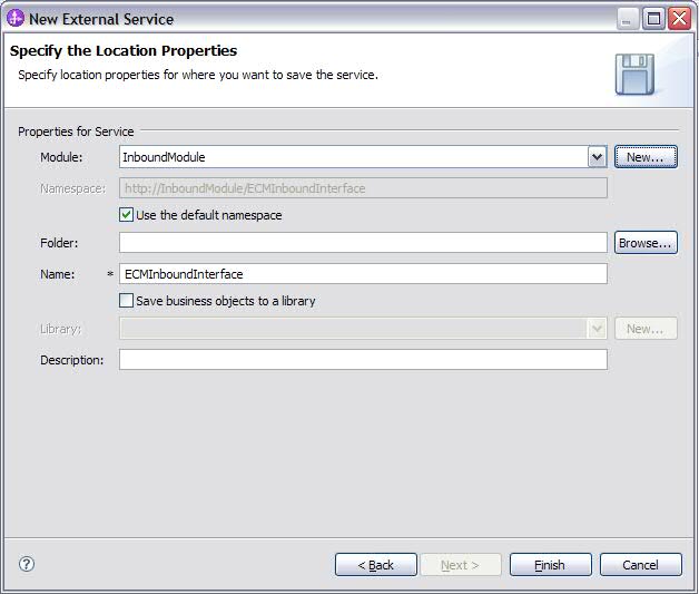
- To use an existing module, select its name from the Module list.
- Set the namespace you want to use for your inbound interface.
- Select Use the default namespace check box to retain the inbound interface to use the default derived namespace. By default, this check box is selected.
- To specify a different namespace, clear Use the default namespace check box and type a different value in the Namespace field.
- Optional: Set the folder in the new module where the service description is to be saved. In the Folder field, type the folder name or browse to an existing folder. If you do not specify a folder name, the artifacts (the import, XSD, and WSDL files) are stored in the root folder of the module (the folder with the module name).
- In the Name field, accept the default import name or type a different name.
- To save business objects in a library where they can be used by other modules, select Save business objects to a library check box and specify the location of the library in the Library field.
- Optional: In the Description field, type a descriptive comment about the module.
- Click Finish to complete the setting of location properties.
If the Model Changed window is displayed, click Yes.
The wizard exits. The artifacts are generated.
Modify artifacts
Often business requirements mandate changes to the backend enterprise information system (EIS) data structures. These changes call for regeneration and reconfiguration of artifacts (import and export) that were previously generated using the external service wizard.
A few business scenarios where the output from one enterprise service discovery flow can be reused in successive flows, are outlined as follows:
- When to add a new object to the object set.
- When you want to modify configurations on selected objects like changes to operations, operation names, and service level settings like security, transactions, and reliability.
- When you want to remove a discovered object from the object set.
- When you want to rediscover existing objects in the service to synchronize the service if the objects in the back-end system have been updated.
To modify existing artifacts, you can invoke the wizard in one of the following ways. The external service wizard is initialized with previously configured settings.
- In the assembly editor, select the component you want to modify, right-click, and select Edit Binding.
- In the Business Integration view, select the component you want to modify, right-click, and select Edit Binding.
- Select the component in the assembly editor and select the Properties view. In the Binding tab, click the Edit link.
The Edit Binding option is available for artifacts generated using IBM Integration Designer 7.0 only. If you are importing a project interchange from an earlier version of IBM Integration Designer, the Edit Binding option is not available. If you have made any manual changes to the configuration, running the wizard again will overwrite these changes.
- Modify service import Modify an import component by rediscovering and reconfiguring the objects using the Edit Binding option in IBM Integration Designer.
- Modify service export Modify an export component by rediscovering and reconfiguring the objects using the Edit Binding option in IBM Integration Designer.
Previous topic: Configure the module for deployment
Next topic: Deploy the module for production
Modify service import
Modify an import component by rediscovering and reconfiguring the objects using the Edit Binding option in IBM Integration Designer. You can invoke the external service wizard to modify the information of a service import interface. The wizard automatically populates the existing information for the selected import interface. You can modify the objects and services, and then regenerate the import component with the modified data.
- Start the external service wizard for the selected service interface import component using one of the following methods.
- In the assembly editor, select the component you want to modify, right-click and select Edit Binding.
- In the Business Integration view, select the component you want to modify, right-click and select Edit Binding.
- Select the interface in the assembly editor and select the Properties view. In the Binding tab, click the Edit link.
The Find Objects in the Enterprise System window of the external service wizard is displayed. The external service wizard automatically populates the existing configuration details for the selected import interface.
- In the Find Objects in the Enterprise System window, make the required changes. For more information about discovering
objects, see Discovering and selecting objects.
To change the connection properties for the external service wizard, click Back and change the properties in the Set the Discovery Properties window. See Set connection properties for the external service wizard.
- To modify the configuration of an object from the Selected objects list, select the object name and then click the
 (Edit) icon.
- To remove an object from the Selected objects list, select the object name, and then click the
 (Remove) button.
- To modify the configuration of an object from the Selected objects list, select the object name and then click the
- Click Next. If you click Cancel, the changes you made in the previous step does not take effect.
- In the Specify Composite Properties window, you can modify the existing operations or add more operations to the selected object. For more information about the configuration procedure, see Configure the selected objects.
- Click Next.
- In the Service Generation window, modify the service operations if required.
- Click Finish. The artifacts are regenerated.
- Complete any other required manual configuration.
The artifacts are updated.
You can test and deploy your module.
Modify service export
Modify an export component by rediscovering and reconfiguring the objects using the Edit Binding option in IBM Integration Designer. You can invoke the external service wizard to modify the information of a service export interface. The wizard automatically populates the existing information for the selected export interface. You can modify the objects and services, and then regenerate the export component with the modified data.
- Start the external service wizard for the selected service interface export component using one of the following methods.
- In the assembly editor, select the component you want to modify, right-click and select Edit Binding.
- In the Business Integration view, select the component you want to modify, right-click and select Edit Binding.
- Select the interface in the assembly editor and select the Properties view. In the Binding tab, click the Edit link.
The Find Objects in the Enterprise System window of the external service wizard is displayed. The external service wizard automatically populates the existing configuration details for the selected export interface.
- In the Find Objects in the Enterprise System window, make the required changes. For more information about discovering
objects, see Discovering and selecting objects.
To change the connection properties for the external service wizard, click Back and change the properties in the Set the Discovery Properties window. See Set connection properties for the external service wizard.
- To modify the configuration of an object from the Selected objects list, select the object name and then click the (Edit) icon.
- To remove an object from the Selected objects list, select the object name, and then click the (Remove) button.
- To modify the configuration of an object from the Selected objects list, select the object name and then click the
- Click Next. If you click Cancel, the changes you made in the previous step does not take effect.
- In the Specify Composite Properties window, you can modify the existing operations or add more operations to the selected object. For more information about the configuration procedure, refer to Configure the selected objects.
- Click Next.
- In the Service Generation window, modify the service operations if required.
- Click Finish. The artifacts are regenerated.
- Complete any other required manual configuration.
The artifacts are updated.
You can test and deploy your module.
Change interaction specification properties
To change interaction specification properties for your adapter module after generating the service, use the assembly editor in IBM Integration Designer.
You must have used the external service wizard to generate a service for the adapter.
You might want to change interaction specification properties after you have generated a service for the adapter. Interaction specification properties, which are optional, are set at the method level, for a specific operation on a specific business object. The values you specify appear as defaults in all parent business objects generated by the external service wizard. You can change these properties before you export the EAR file. You cannot change these properties after you deploy the application.
To change the interaction specification properties, use the following procedure:
- From the Business Integration perspective of IBM Integration Designer, expand the module name.
- Expand Assembly Diagram and double-click the interface.
- Click the interface in the assembly editor. The module properties are displayed.
- Click the Properties tab. You can also right-click the interface in the assembly diagram and click Show in Properties.
- Under Binding, click Method bindings. The methods for the interface are displayed, one for each combination of business object and operation.
- Select the method whose interaction specification property you want to change.
The interaction specification properties associated with your adapter module are changed.
Deploy the module.
Deploy the module
Deploy a module to place the files that make up your module and adapter into an operational environment for production or testing. In IBM Integration Designer, the integrated test environment features runtime support for BPM or WebSphere Enterprise Service Bus, or both, depending on the test environment profiles that you selected during installation.
- Deployment environments There are test and production environments into which you can deploy modules and adapters.
- Deploy the module for testing In IBM Integration Designer, you can deploy a module that includes an embedded adapter to the test environment and work with server tools that enable you to perform such tasks as editing server configurations, starting, and stopping servers and testing the module code for errors. The testing is generally performed on the interface operations of your components, which enables you to determine whether the components are correctly implemented and the references are correctly wired.
- Deploy the module for production Deploying a module created with the external service wizard to IBM Business Process Manager or WebSphere Enterprise Service Bus in a production environment is a two-step process. First, you export the module in IBM Integration Designer as an enterprise archive (EAR) file. Second, you deploy the EAR file using the BPM or WebSphere Enterprise Service Bus administrative console.
- Deploy the module in a clustered environment In IBM Integration Designer, you can deploy the IBM WebSphere Adapter for Enterprise Content Management in a clustered environment.
Deployment environments
There are test and production environments into which you can deploy modules and adapters.
In IBM Integration Designer, you can deploy your modules to one or more servers in the test environment. This is typically the most common practice for running and testing business integration modules. However, you can also export modules for server deployment on IBM Business Process Manager or WebSphere Enterprise Service Bus as EAR files using the administrative console or command-line tools.
Deploy the module for testing
In IBM Integration Designer, you can deploy a module that includes an embedded adapter to the test environment and work with server tools that enable you to perform such tasks as editing server configurations, starting, and stopping servers and testing the module code for errors. The testing is generally performed on the interface operations of your components, which enables you to determine whether the components are correctly implemented and the references are correctly wired.
- Generating and wiring a target component for testing inbound processing Before deploying to the test environment a module that includes an adapter for inbound processing, you must first generate and wire a target component. This target component serves as the destination to which the adapter sends events.
- Add the module to the server In IBM Integration Designer, you can add modules to one or more servers in the test environment.
- Testing the module for outbound processing using the test client Test the assembled module and adapter for outbound processing using the IBM Integration Designer integration test client.
Generating and wiring a target component for testing inbound processing
Before deploying to the test environment a module that includes an adapter for inbound processing, you must first generate and wire a target component. This target component serves as the destination to which the adapter sends events.
You must have generated an export module, using the external service wizard.
Generating and wiring a target component for inbound processing is required in a testing environment only. It is not necessary when deploying the adapter in a production environment.
The target component receives events. You wire the export to the target component (connecting the two components) using the assembly editor in IBM Integration Designer. The adapter uses the wire to pass event data (from the export to the target component).
- Create the target component.
- From the Business Integration perspective of IBM Integration Designer, expand Assembly Diagram and double-click the export component. If you did not change the default value, the name of the export component is the name of your adapter + InboundInterface.
An interface specifies the operations that can be called and the data that is passed, such as input arguments, returned values, and exceptions. The InboundInterface contains the operations required by the adapter to support inbound processing and is created when you run the external service wizard.
- Create a new component by expanding Components,
selecting Untyped Component, and dragging the component to the Assembly Diagram.
The cursor changes to the placement icon.
- Click the component to have it displayed in the Assembly Diagram.
- From the Business Integration perspective of IBM Integration Designer, expand Assembly Diagram and double-click the export component. If you did not change the default value, the name of the export component is the name of your adapter + InboundInterface.
- Wire the components.
- Click and drag the export component to the new component.
Save the assembly diagram. Click File > Save.
- Click and drag the export component to the new component.
- Generate an implementation for the new component.
- Right-click on the new component and select Generate Implementation > Java.
- Select (default package) and click OK. This creates an endpoint for the inbound module.
The Java™ implementation is displayed in a separate tab.
- Optional: Add print statements to print the data object received at the endpoint for each of the endpoint methods.
- Click File > Save to save the changes.
- Right-click on the new component and select Generate Implementation > Java.
Continue deploying the module for testing.
Next topic: Add the module to the server
Add the module to the server
In IBM Integration Designer, you can add modules to one or more servers in the test environment.
If the module you are testing uses an adapter to perform inbound processing, generate and wire a target component to which the adapter sends the events.
In order to test your module and its use of the adapter, you need to add the module to the server.
- Conditional: If there are no servers in the Servers view, add and define a new server by performing the following steps:
- Place your cursor in the Servers view, right-click, and select New > Server.
- From the Define a New Server window, select the server type.
- Configure servers settings.
- Click Finish to publish the server.
- Place your cursor in the Servers view, right-click, and select New > Server.
- Add the module to the server.
- Switch to the servers view. In IBM Integration Designer, select Windows > Show View > Servers.
- Start the server. In the Servers tab in the lower-right pane of the IBM Integration Designer screen, right-click the server and then select Start.
- When the server status is Started, right-click the server and select Add and Remove Projects.
- In the Add and Remove Projects screen, select your project and click Add. The project moves from the Available projects list to the Configured projects list.
- Click Finish. This deploys
the module on the server.
The Console tab in the lower-right pane displays a log while the module is being added to the server.
Test the functionality of your module and the adapter.
Previous topic: Generating and wiring a target component for testing inbound processing
Next topic: Testing the module for outbound processing using the test client
Testing the module for outbound processing using the test client
Test the assembled module and adapter for outbound processing using the IBM Integration Designer integration test client.
You need to add the module to the server first.
Testing a module is performed on the interface operations of your components, which enables you to determine whether the components are correctly implemented and the references are correctly wired.
- Select the module you want to test, right-click on it, and select Test > Test Module.
- Follow the instructions for Testing modules and components at the Related tasks link of this topic.
If you are satisfied with the results of testing your module and adapter, you can deploy the module and adapter to the production environment.
Previous topic: Add the module to the server
Related tasks:
Testing modules and components in WebSphere Integration Developer
Deploy the module for production
Deploy a module created with the external service wizard to IBM Business Process Manager or WebSphere Enterprise Service Bus in a production environment is a two-step process. First, you export the module in IBM Integration Designer as an enterprise archive (EAR) file. Second, you deploy the EAR file using the BPM or WebSphere Enterprise Service Bus administrative console.
- Install the RAR file (for modules using stand-alone adapters only) If you chose not to embed the adapter with your module, but instead choose to make the adapter available to all deployed applications in the server instance, you need to install the adapter in the form of a RAR file to the application server. A RAR file is a Java™ archive (JAR) file used to package a resource adapter for the Java EE Connector Architecture (JCA).
- Export the module as an EAR file Using IBM Integration Designer, export your module as an EAR file. By creating an EAR file, you capture all of the contents of your module in a format that can be easily deployed to IBM Business Process Manager or WebSphere Enterprise Service Bus.
- Install the EAR file Installing the EAR file is the last step of the deployment process. When you install the EAR file on the server and run it, the adapter, which is embedded as part of the EAR file, runs as part of the installed application.
Previous topic: Modify artifacts
Next topic: Configure logging and tracing
Install the RAR file (for modules using stand-alone adapters only)
If you chose not to embed the adapter with your module, but instead choose to make the adapter available to all deployed applications in the server instance, you need to install the adapter in the form of a RAR file to the application server. A RAR file is a Java™ archive (JAR) file used to package a resource adapter for the Java EE Connector Architecture (JCA).
You must set Deploy connector project to On server for use by multiple adapters in the Set the Service Generation and Deployment Properties window of the external service wizard.
Install the adapter in the form of a RAR file results in the adapter being available to all Java EE application components running in the server run time.
- If the server is not running, right-click your server in the Servers view and select Start.
- When the server status changes to Started, right-click the server and select Administration > Run administrative console.
- Log on to the administrative console.
- Click Resources > Resource Adapters > Resource adapters.
- In the Resource adapters page, click Install RAR.
Figure 1. The Install RAR button on the Resource adapters page

- In the Install RAR file page, click Browse and navigate to the RAR file for your adapter.
The RAR files are typically installed in the following path: IID_installation_directory/ResourceAdapters/adapter_name/adapter.rar
- Click Next.
- Optional: In the Resource adapters page, change the name of the adapter and add a description.
- Click OK.
- Click Save in the Messages box at the top of the page.
The next step is to export the module as an EAR file that you can deploy on the server.
Next topic: Export the module as an EAR file
Export the module as an EAR file
Use IBM Integration Designer, export your module as an EAR file. By creating an EAR file, you capture all of the contents of your module in a format that can be easily deployed to IBM Business Process Manager or WebSphere Enterprise Service Bus.
Before you can export a module as an EAR file, you must have created a module to communicate with your service. The module should be displayed in the IBM Integration Designer Business Integration perspective.
To export the module as an EAR file, perform the following procedure.
- Right-click the module and select Export.
- In the Select window, expand Java EE.
- Select EAR file and click Next.
- Optional: Select the correct EAR application. The EAR application is named after your module, but with "App" added to the end of the name.
- Browse for the folder on the local file system where the EAR file will be placed.
- To export the source files, select the Export source files check box. This option is provided in case you want to export the source files in addition to the EAR file. Source files include files associated with Java™ components, data maps, and so on.
- To overwrite an existing file, click Overwrite existing file.
- Click Finish.
The contents of the module are exported as an EAR file.
Install the module in the administrative console.
This deploys the module to IBM Business Process Manager or WebSphere Enterprise Service Bus.
Previous topic: Install the RAR file (for modules using stand-alone adapters only)
Next topic: Install the EAR file
Install the EAR file
Install the EAR file is the last step of the deployment process. When you install the EAR file on the server and run it, the adapter, which is embedded as part of the EAR file, runs as part of the installed application.
You must have exported your module as an EAR file before you can install it on IBM Business Process Manager or WebSphere Enterprise Service Bus.
To install the EAR file, perform the following procedure. For more information about clustering adapter module applications, see the http://www.ibm.com/software/webservers/appserv/was/library/.
- If the server is not running, right-click your server in the Servers view and select Start.
- When the server status changes to Started, right-click the server and select Administration > Run administrative console.
- Log on to the administrative console.
- Click Applications > New Application > New Enterprise Application.
Figure 1. Preparing for the application installation window

- Click Browse to locate your EAR file and click Next. The EAR file name is the name of the module followed by "App."
- If you are deploying to a clustered environment.
- On the Step 2: Map modules to servers window, select the module and click Next.
- Select the name of the server cluster.
- Click Apply.
- Click Next. In the Summary page, verify the settings and click Finish.
- If you are using an authentication alias:
- Expand Security and select Business Integration Security.
- Select the authentication alias to configure. You must have administrator or operator rights to change the authentication alias configurations.
- If it is not already specified, type the User name.
- If it is not already specified, type the Password.
- If it is not already specified, type the password again in the Confirm Password field.
- Click OK.
The project is now deployed and the Enterprise Applications window is displayed.
To set or reset any properties or you would like to cluster adapter project applications, make those changes using the administrative console before configuring troubleshooting tools.
Previous topic: Export the module as an EAR file
Deploy the module in a clustered environment
In IBM Integration Designer, you can deploy the IBM WebSphere Adapter for Enterprise Content Management in a clustered environment.
To deploy the module in a clustered environment, use any of the following approaches.
- Deploy module embedded in the application The adapter is deployed embedded in the application and specific to it. The adapter cannot be shared between multiple applications.
- Deploy module at node level with embedded activation specification The adapter is deployed at the node level, with the activation specification created during module creation. The adapter can be shared across multiple applications.
- Deploy module at node level with JNDI activation specification The adapter is deployed at the node level, and the application provides a JNDI reference to the activation specification. Create the activation specification with the same JNDI name at the cluster scope from the administrative console. The adapter can be shared across multiple applications
Deploy module embedded in the application
The adapter is deployed embedded in the application and specific to it. The adapter cannot be shared between multiple applications.
The following steps are a necessary prerequisite to configure and deploy the module.
- IBM Integration Designer version 7.5.0.0 or above.
- A clustered topology deployment environment on the BPM or WebSphere Enterprise Service Bus available from IBM Integration Designer.
- Create a clustered topology deployment environment, as shown in the following Gold Topology configuration figure.
Figure 1. Deployment environment

- Deploy the adapter and the adapter applications (EAR files) in the AppTarget (the target that hosts the SCA container).
Figure 2. Deployment environment showing server clusters

To create an application with the embedded adapter, use the external service wizard.
- In the Service Configuration Properties window, from the Deploy connector project property list, select With module for use by single application.
- Create the module as described in the Business process management samples for WebSphere Adapters.
- In the Dependencies option for the module, after the module is created, ensure the Deploy with module option is selected for the adapter.
- If the server is not running, right-click your server in the Servers view and select Start.
- When the server status changes to Started,
right-click the server and select Administration > Run administrative console.
- From the Deployment Manager Admin Console, click Install applications to deploy the application.
- On the Step 2: Map modules to servers window, select the module and click Next. For the embedded adapter option, the adapter is deployed as part of the application.
- In the Enterprise Applications view, select the new application <adapter_name>EmbeddedModuleApp. The new application is displayed after the application is deployed at the deployment manager level.
- Select the node and click Installed applications to view the deployed application on each individual node.
The resource adapter is embedded and deployed as part of the application.
Deploy module at node level with embedded activation specification
The adapter is deployed at the node level, with the activation specification created during module creation. The adapter can be shared across multiple applications.
The following steps are a necessary prerequisite to configure and deploy the module.
- IBM Integration Designer version 7.5.0.0 or above.
- A clustered topology deployment environment on the BPM or WebSphere Enterprise Service Bus available from IBM Integration Designer.
- Create a clustered topology deployment environment, as shown in the following Gold Topology configuration figure.
Figure 1. Deployment environment
- Deploy the adapter and the adapter applications (EAR files) in the AppTarget (the target that hosts the SCA container).
Figure 2. Deployment environment showing server clusters
To create an application with the node level adapter and activation specification properties specified in the module itself, use the external service wizard.
- In the Service Configuration Properties window, from the Deploy connector project property list, select On server for use by multiple applications.
- From the Connection properties list, select Use properties below.
- Create the module as described in the Business process management samples for WebSphere Adapters.
- In the Dependencies option for the module, ensure the Deploy with module option is not selected for the adapter. Here, the adapter is not part of the module, therefore you must deploy the adapter before deploying the application.
- If the server is not running, right-click your server in the Servers view and select Start.
- When the server status changes to Started, right-click the server and select Administration > Run administrative console. Log on to the administrative console.
- To deploy the adapter at individual nodes, click Resources > Resource Adapters > Resource adapters. In the clustered environment, install the adapter in each node separately.
- In the Resource adapters page, click Install RAR.
- In the Install RAR file page, click Browse and navigate to the RAR file for your adapter. Deploy the RAR on each node.
The RAR files are typically installed in the following path: IID_installation_directory/ResourceAdapters/adapter_name/adapter.rar
- For deployment at node level, do not select any Scope because the scope is always Node. Click Next.
- Optional: In the Resource adapters page, change the name of the adapter and add a description. Click OK.
- Click Save in the Messages box at the top of the page.
- For node level deployment, check if the adapter RAR is deployed at the node level.
- To deploy the adapter at the cluster level, click Resources > Resource Adapters > Resource adapters.
- In the Resource adapters window, set the Scope to Cluster, and then click New.
- Select the RAR deployed at the node level.
- Check if the adapter RAR is now deployed at the cluster level.
Deploy the application after the adapter is deployed at the node level on the individual nodes, and then at the cluster level.
- From the Deployment Manager Admin Console, click Install applications to deploy the application.
- On the Step 2: Map modules to servers window, select the module and click Next. The adapter is not part of the deployed application.
- In the Admin Console, click Resources > Resource Adapters > IBM WebSphere Adapter for Enterprise Content Management > J2C activation specifications to view the activation specification from the adapter deployed at the cluster level.
The resource adapter is deployed at the node level, with the activation specification.
Deploy module at node level with JNDI activation specification
The adapter is deployed at the node level, and the application provides a JNDI reference to the activation specification. Create the activation specification with the same JNDI name at the cluster scope from the administrative console. The adapter can be shared across multiple applications
The following steps are a necessary prerequisite to configure and deploy the module.
- IBM Integration Designer version 7.5.0.0 or above.
- A clustered topology deployment environment on the BPM or WebSphere Enterprise Service Bus available from IBM Integration Designer.
- Create a clustered topology deployment environment, as shown in the following Gold Topology configuration figure.
Figure 1. Deployment environment
- Deploy the adapter and the adapter applications (EAR files) in the AppTarget (the target that hosts the SCA container).
Figure 2. Deployment environment showing server clusters
To create an application with the node level adapter and activation specification properties specified in the module itself, use the external service wizard.
- In the Service Configuration Properties window, from the Deploy connector project property list, select On server for use by multiple applications.
- From the Connection properties list, select Use JNDI lookup name configured on server.
- In the JNDI lookup name property field, specify the JNDI name. Use this same JNDI name when you create the activation specification from the Admin Console.
- Create the module as described in the Business process management samples for WebSphere Adapters.
- In the Dependencies option for the module, ensure the Deploy with module option is not selected for the adapter.
- If the server is not running, right-click your server in the Servers view and select Start.
- When the server status changes to Started, right-click the server and select Administration > Run administrative console. Log on to the administrative console.
- To install the adapter at the node level, click Resources > Resource Adapters > Resource adapters. In the clustered environment, install the adapter in each node separately.
- In the Resource adapters page, click Install RAR.
- In the Install RAR file page, click Browse and navigate to the RAR file for your adapter. Deploy the RAR on each node.
The RAR files are typically installed in the following path: IID_installation_directory/ResourceAdapters/adapter_name/adapter.rar
- For deployment at node level, do not select any Scope because the scope is always Node. Click Next.
- Optional: In the Resource adapters page, change the name of the adapter and add a description. Click OK.
- Click Save in the Messages box at the top of the page.
- To install the RAR at the cluster level, click Resources > Resource Adapters > Resource adapters
- In the Resource adapters page, set the Scope to Cluster, and then click New.
- Select the RAR deployed at the node level, and then check if the adapter RAR is now deployed at the cluster level. Deploy the application after the adapter is deployed at the node level on the individual nodes, and then at the cluster level.
- From the Deployment Manager Admin Console, click Install applications to deploy the application.
- In the Admin Console, click Resources > Resource Adapters > IBM WebSphere Adapter for Enterprise Content Management > J2C activation specifications > New to create the activation specification from the adapter deployed at the cluster level.
- When installing the adapter, in the Name field, enter the same name as defined in the RAR.
- In the JNDI name field, enter the same name as given during the module creation.
- Click Resources > Resource Adapters > IBM WebSphere Adapter for Enterprise Content Management > J2C activation specifications to check if the JNDI reference on the adapter is same as the one specified for the module.
- Click Resources > Resource Adapters > IBM WebSphere Adapter for Enterprise Content Management > J2C activation specifications > Custom properties to set values for the activation specification in the Admin Console.
- From the Deployment Manager Admin console, click Install applications to deploy the application after you deploy the RAR and create the activation specification.
- On the Step 2: Map modules to servers page, select the module and click Next. The adapter is not part of the deployed application.
The resource adapter is deployed at the node level, with the JNDI activation specification reference.
Administer the adapter module
When you are running the adapter in a stand-alone deployment, use the administrative console of the server to start, stop, monitor, and troubleshoot the adapter module. In an application that uses an embedded adapter, the adapter module starts or stops when the application is started or stopped.
- Configure logging and tracing Configure logging and tracing to suit your requirements. Enable logging for the adapter to control the status of event processing. Change the adapter log and trace file names to separate them from other log and trace files.
- Change configuration properties for embedded adapters To change the configuration properties after you deploy the adapter as part of a module, use the administrative console of the runtime environment. For information about configuring logging properties and changing the log and trace file names, see Configure logging and tracing.
- Change configuration properties for stand-alone adapters To set configuration properties after you install a stand-alone adapter, use the administrative console of the runtime environment. Provide the general information about the adapter and then set the resource adapter properties (which are used for general adapter operation). If the adapter is used for outbound operations, create a connection factory and then set the properties for it. For information about configuring logging properties and changing the log and trace file names, see Configure logging and tracing.
- Start the application that uses the adapter Use the administrative console of the server to start an application that uses the adapter. By default, the application starts automatically when the server starts.
- Stop the application that uses the adapter Use the administrative console of the server to stop an application that uses the adapter. By default, the application stops automatically when the server stops.
- Monitor performance using Performance Monitoring Infrastructure Performance Monitoring Infrastructure (PMI) is a feature of the administrative console that allows you to dynamically monitor the performance of components in the production environment, including IBM WebSphere Adapter for Enterprise Content Management. PMI collects adapter performance data, such as average response time and total number of requests, from various components in the server and organizes the data into a tree structure. You can view the data through the Tivoli Performance Viewer, a graphical monitoring tool that is integrated with the administrative console in BPM or WebSphere Enterprise Service Bus.
- Enable tracing with the Common Event Infrastructure The adapter can use the Common Event Infrastructure (CEI), a component embedded in the server, to report data about critical business events such as the starting or stopping of a poll cycle. Event data can be written to a database or a trace log file depending on configuration settings.
Configure logging and tracing
Configure logging and tracing to suit your requirements. Enable logging for the adapter to control the status of event processing. Change the adapter log and trace file names to separate them from other log and trace files.
- Configure logging properties Use the administrative console to enable logging and to set the output properties for a log, including the location, level of detail, and output format of the log.
- Change the log and trace file names To keep the adapter log and trace information separate from other processes, use the administrative console to change the file names. By default, log and trace information for processes and applications on a Process Server is written to the SystemOut.log and trace.log files.
Previous topic: Deploy the module for production
Next topic: Start the application that uses the adapter
Related tasks:
Configure logging properties
Use the administrative console to enable logging and to set the output properties for a log, including the location, level of detail, and output format of the log. Before the adapters can log monitored events, you must specify the service component event points to monitor, what level of detail you require for each event, and format of the output used to publish the events to the logs. Use the administrative console to perform the following tasks:
- Enable or disable a particular event log
- Set the level of detail in a log
- Specify where log files are stored and how many log files are kept
- Set the format for log output
If you set the output for log analyzer format, you can open trace output using the Log Analyzer tool, which is an application included with your Process Server. This is useful if you are trying to correlate traces from two different server processes, because it allows you to use the merge capability of the Log Analyzer.
For more information about monitoring on a Process Server, including service components and event points, see http://publib.boulder.ibm.com/infocenter/dmndhelp/v7r5m1/topic/com.ibm.wbpm.admin.doc/topics/welcome_wps_mon.html.
You can change the log configuration statically or dynamically. Static configuration takes effect when you start or restart the application server. Dynamic or run time configuration changes apply immediately.
When a log is created, the detail level for that log is set from the configuration data. If no configuration data is available for a particular log name, the level for that log is obtained from the parent of the log. If no configuration data exists for the parent log, the parent of that log is checked, and so on, up the tree, until a log with a non-null level value is found. When you change the level of a log, the change is propagated to the child logs, which recursively propagate the change to their child log, as necessary.
To enable logging and set the output properties for a log, use the following procedure.
- In the navigation pane of the administrative console, select Servers > WebSphere application servers.
- Click the name of the server to work with.
- Under Troubleshooting, click Logging and tracing.
- Click Change log detail levels.
- Specify when you want the change to take effect:
- For a static change to the configuration, click the Configuration tab.
- For a dynamic change to the configuration, click the Runtime tab.
- For a static change to the configuration, click the Configuration tab.
- Click the names of the packages whose logging level you want to modify. The package names for WebSphere Adapters start with com.ibm.j2ca.*:
- For the adapter base component, select com.ibm.j2ca.base.*.
- For the adapter base component and all deployed adapters, select com.ibm.j2ca.*.
- For the WebSphere Adapter for Enterprise Content Management only, select the com.ibm.j2ca.ECMRA<ADAPTER-ID> package.
- For the adapter base component, select com.ibm.j2ca.base.*.
- Select the logging level.
Logging Level Description Fatal The task cannot continue or the component cannot function. Severe The task cannot continue, but the component can still function. This logging level also includes conditions that indicate an impending fatal error, that is, situations that strongly suggest that resources are on the verge of being depleted. Warning A potential error has occurred or a severe error is impending. This logging level also includes conditions that indicate a progressive failure, for example, the potential leaking of resources. Audit A significant event has occurred that affects the server state or resources. Info The task is running. This logging level includes general information outlining the overall progress of a task. Config The status of a configuration is reported or a configuration change has occurred. Detail The subtask is running. This logging level includes general information detailing the progress of a subtask. - Click Apply.
- Click OK.
- To have static configuration changes take effect, stop and then restart the Process Server.
Log entries from this point forward contain the specified level of information for the selected adapter components.
Next topic: Change the log and trace file names
Change the log and trace file names
To keep the adapter log and trace information separate from other processes, use the administrative console to change the file names. By default, log and trace information for processes and applications on a Process Server is written to the SystemOut.log and trace.log files.
You can change the log and trace file names at any time after the adapter module has been deployed to an application server. You can change the log and trace file names statically or dynamically. Static changes take effect when you start or restart the application server. Dynamic or run time changes apply immediately.
Log and trace files are in the install_root/profiles/profile_name/logs/server_name folder.
To set or change the log and trace file names, use the following procedure.
- In the navigation pane of the administrative console, select Applications >Application Types>WebSphere enterprise applications.
- In the Enterprise Applications list, click the name of the adapter application. This is the name of the EAR file for the adapter, but without the ear file extension. For example, if the EAR file is named Accounting_OutboundApp.ear, then click Accounting_OutboundApp.
- In the Configuration tab, select Modules>Manage Modules.
- In the list of modules, click IBM WebSphere Adapter for Enterprise Content Management.
- In the Configuration tab, under Additional Properties, click Resource Adapter.
- In the Configuration tab, under Additional Properties, click Custom properties.
- In the Custom Properties table, change the file names.
- Click either logFilename to change the name of the log file or traceFilename to change the name of the trace file.
- In the Configuration tab, type the new name in the Value field. By default, the log file is called SystemOut.log and the trace file is called trace.log.
- Click Apply or OK. Your changes are saved on your local machine.
- To save your changes to the master configuration on the server, use one of the following procedures:
- Static change: Stop and restart the server. This method allows you to make changes, but those changes do not take effect until you stop and start the server.
- Dynamic change: Click the Save link in the Messages box above the Custom properties table. Click Save again when prompted.
Previous topic: Configure logging properties
Change configuration properties for embedded adapters
To change the configuration properties after you deploy the adapter as part of a module, use the administrative console of the runtime environment. For information about configuring logging properties and changing the log and trace file names, see Configure logging and tracing.
- Set resource adapter properties for embedded adapters To set resource adapter properties for your adapter after it has been deployed as part of a module, use the administrative console. You select the name of the property you want to configure and then change or set the value.
- Set managed (J2C) connection factory properties for embedded adapters To set managed connection factory properties for your adapter after it has been deployed as part of a module, use the administrative console. You select the name of the property you want to configure and then change or set the value.
- Set activation specification properties for embedded adapters To set activation specification properties for your adapter after it has been deployed as part of a module, use the administrative console. You select the name of the message endpoint property you want to configure, and then change or set the value.
Related reference:
Set resource adapter properties for embedded adapters
To set resource adapter properties for your adapter after it has been deployed as part of a module, use the administrative console. You select the name of the property you want to configure and then change or set the value.
Your adapter module must be deployed on IBM Business Process Manager or WebSphere Enterprise Service Bus.
Custom properties are default configuration properties shared by all IBM WebSphere Adapters.
To configure properties using the administrative console, use the following procedure:
- If the server is not running, right-click your server in the Servers view and select Start.
- When the server status changes to Started, right-click the server and select Administration > Run administrative console.
- Log on to the administrative console.
- Select Applications > Application Types > WebSphere enterprise application.
- From the Enterprise Applications list, click the name of the adapter module whose properties you want to change. The Configuration page is displayed.
Figure 1. The Manage Modules selection in the Configuration tab

- Under Modules, click Manage Modules.
- Click IBM WebSphere Adapter for Enterprise Content Management.
- From the Additional Properties list, click Resource Adapter.
- On the next page, from the Additional Properties list, click Custom properties.
- For each property you want to change.
See Resource adapter properties for more information about these properties.
- Click the name of the property.
The Configuration page for the selected property is displayed.
- Change the contents of the Value field or type a value, if the field is empty.
- Click OK.
- Click the name of the property.
- In the Messages area, click Save.
The resource adapter properties associated with your adapter module are changed.
Related tasks:
Set managed (J2C) connection factory properties for embedded adapters
Set activation specification properties for embedded adapters
Related reference:
Feedback adapters,IBM WebSphere Adapter for Enterprise Content Management
Set managed (J2C) connection factory properties for embedded adapters
To set managed connection factory properties for your adapter after it has been deployed as part of a module, use the administrative console. You select the name of the property you want to configure and then change or set the value.
Your adapter module must be deployed on IBM Business Process Manager or WebSphere Enterprise Service Bus.
You use managed connection factory properties to configure the target CMIS server instance.
In the administrative console, the properties are referred to as "J2C connection factory properties."
To configure properties using the administrative console, use the following procedure.
- If the server is not running, right-click your server in the Servers view and select Start.
- When the server status changes to Started, right-click the server and select Administration > Run administrative console.
- Log on to the administrative console.
- Select Applications > Application Types > WebSphere enterprise application.
- In the Enterprise Applications list, click the name of the adapter module whose properties you want to change.
Figure 1. The Manage Modules selection in the Configuration tab
- Under Modules, click Manage Modules.
- Click IBM WebSphere Adapter for Enterprise Content Management.
- In the Additional Properties list, click Resource Adapter.
- On the next page, from the Additional Properties list, click J2C connection factories.
- Click the name of the connection factory associated with your adapter module.
- In the Additional Properties list, click Custom properties.
Custom properties are those J2C connection factory properties that are unique to IBM WebSphere Adapter for Enterprise Content Management. Connection pool and advanced connection factory properties are properties you configure if you are developing your own adapter.
- For each property you want to change.
See Managed (J2C) connection factory properties for more information about these properties.
- Click the name of the property.
- Change the contents of the Value field or type a value, if the field is empty.
- Click OK.
- In the Messages area, click Save.
The managed connection factory properties associated with your adapter module are changed.
Related tasks:
Set resource adapter properties for embedded adapters
Set activation specification properties for embedded adapters
Related reference:
Managed (J2C) connection factory properties
Set activation specification properties for embedded adapters
To set activation specification properties for your adapter after it has been deployed as part of a module, use the administrative console. You select the name of the message endpoint property you want to configure, and then change or set the value.
Your adapter module must be deployed on IBM Business Process Manager or WebSphere Enterprise Service Bus.
You use activation specification properties to configure the endpoint for inbound processing.
To configure properties using the administrative console, use the following procedure.
- If the server is not running, right-click your server in the Servers view and select Start.
- When the server status changes to Started, right-click the server and select Administration > Run administrative console.
- Log on to the administrative console.
- Select Applications > Application Types > WebSphere enterprise application.
- From the Enterprise Applications list, click the name of the adapter module whose properties you want to change.
Figure 1. The Manage Modules selection in the Configuration tab
- Under Modules, click Manage Modules.
- Click IBM WebSphere Adapter for Enterprise Content Management.
- From the Additional Properties list, click Resource Adapter.
- On the next page, from the Additional Properties list, click J2C activation specifications.
- Click the name of the activation specification associated with the adapter module.
- From the Additional Properties list, click J2C activation specification custom properties.
- For each property you want to change.
- Click the name of the property.
- Change the contents of the Value field or type a value, if the field is empty.
- Click OK.
- In the Messages area, click Save.
The activation specification properties associated with your adapter module are changed.
Related tasks:
Set resource adapter properties for embedded adapters
Set managed (J2C) connection factory properties for embedded adapters
Change configuration properties for stand-alone adapters
To set configuration properties after you install a stand-alone adapter, use the administrative console of the runtime environment. Provide the general information about the adapter and then set the resource adapter properties (which are used for general adapter operation). If the adapter is used for outbound operations, create a connection factory and then set the properties for it. For information about configuring logging properties and changing the log and trace file names, see Configure logging and tracing.
- Set resource adapter properties for stand-alone adapters To set resource adapter properties for your stand-alone adapter after it has been installed on IBM Business Process Manager or WebSphere Enterprise Service Bus, use the administrative console. You select the name of the property you want to configure and then change or set the value.
- Set managed (J2C) connection factory properties for stand-alone adapters To set managed connection factory properties for your stand-alone adapter after it has been installed on IBM Business Process Manager or WebSphere Enterprise Service Bus, use the administrative console. You select the name of the property you want to configure and then change or set the value.
- Set activation specification properties for stand-alone adapters To set activation specification properties for your stand-alone adapter after it has been installed on IBM Business Process Manager or WebSphere Enterprise Service Bus, use the administrative console. You select the name of the message endpoint property you want to configure, and then change or set the value.
Set resource adapter properties for stand-alone adapters
To set resource adapter properties for your stand-alone adapter after it has been installed on IBM Business Process Manager or WebSphere Enterprise Service Bus, use the administrative console. You select the name of the property you want to configure and then change or set the value.
Your adapter must be installed on IBM Business Process Manager or WebSphere Enterprise Service Bus.
Custom properties are default configuration properties shared by all IBM WebSphere Adapters.
To configure properties using the administrative console, use the following procedure:
- If the server is not running, right-click your server in the Servers view and select Start.
- When the server status changes to Started, right-click the server and select Administration > Run administrative console.
- Log on to the administrative console.
- Click Resources > Resource Adapters > Resource adapters.
- In the Resource adapters page, click IBM WebSphere Adapter for Enterprise Content Management.
- In the Additional Properties list, click Custom properties.
- For each property you want to change.
See Resource adapter properties for more information about these properties.
- Click the name of the property.
- Change the contents of the Value field or type a value, if the field is empty.
- Click OK.
- In the Messages area, click Save.
The resource adapter properties associated with your adapter are changed.
Related reference:
Feedback stand-alone adapters, IBM WebSphere Adapter for Enterprise Content Management
Set managed (J2C) connection factory properties for stand-alone adapters
To set managed connection factory properties for your stand-alone adapter after it has been installed on IBM Business Process Manager or WebSphere Enterprise Service Bus, use the administrative console. You select the name of the property you want to configure and then change or set the value.
Your adapter must be installed on IBM Business Process Manager or WebSphere Enterprise Service Bus.
You use managed connection factory properties to configure the target CMIS server instance.
In the administrative console, the properties are referred to as "J2C connection factory properties."
To configure properties using the administrative console, use the following procedure:
- If the server is not running, right-click your server in the Servers view and select Start.
- When the server status changes to Started, right-click the server and select Administration > Run administrative console.
- Log on to the administrative console.
- Click Resources > Resource Adapters > Resource adapters.
- In the Resource adapters page, click IBM WebSphere Adapter for Enterprise Content Management.
- In the Additional Properties list, click J2C connection factories.
- To use an existing connection factory,
skip ahead to select
from the list of existing connection factories.
If you have selected Specify connection properties when use the external service wizard to configure the adapter module, you do not need to create a connection factory.
If you are creating a connection factory, perform the following steps:
- Click New.
- In the General Properties section of the Configuration tab, type a name for the connection factory. For example, you can type AdapterCF.
- Type a value for JNDI name. For example, you can type com/eis/AdapterCF.
- Optional: Select an authentication alias from the Component-managed authentication alias list.
- Click OK.
- In the Messages area, click Save.
The newly created connection factory is displayed.
Figure 1. User-defined connection factories for use with the resource adapter

- In the list of connection factories, click the one you want to use.
- In the Additional Properties list, click Custom properties.
Custom properties are those J2C connection factory properties that are unique to WebSphere Adapter for Enterprise Content Management. Connection pool and advanced connection factory properties are properties you configure if you are developing your own adapter.
- For each property you want to change.
See Managed (J2C) connection factory properties for more information about these properties.
- Click the name of the property.
- Change the contents of the Value field or type a value, if the field is empty.
- Click OK.
- After you have finished setting properties, click Apply.
- In the Messages area, click Save.
The managed connection factory properties associated with your adapter are set.
Related reference:
Managed (J2C) connection factory properties
Set activation specification properties for stand-alone adapters
To set activation specification properties for your stand-alone adapter after it has been installed on IBM Business Process Manager or WebSphere Enterprise Service Bus, use the administrative console. You select the name of the message endpoint property you want to configure, and then change or set the value.
Your adapter must be installed on IBM Business Process Manager or WebSphere Enterprise Service Bus.
You use activation specification properties to configure the endpoint for inbound processing.
To configure properties using the administrative console, use the following procedure.
- If the server is not running, right-click your server in the Servers view and select Start.
- When the server status changes to Started, right-click the server and select Administration > Run administrative console.
- Log on to the administrative console.
- Click Resources > Resource Adapters > Resource adapters.
- In the Resource adapters page, click IBM WebSphere Adapter for Enterprise Content Management.
- In the Additional Properties list, click J2C activation specifications.
- To use an existing activation specification, skip ahead to select
from an existing list of activation specifications.
If you have selected Use predefined connection properties when use the external service wizard to configure the adapter module, create an activation specification.
If you are creating an activation specification.
- Click New.
- In the General Properties section of the Configuration tab, type a name for the activation specification. For example, you can type AdapterAS.
- Type a value for JNDI name. For example, you can type com/eis/AdapterAS.
- Select a message listener type.
- Click OK.
- Click Save in the Messages box at the top of the page.
The newly created activation specification is displayed.
- In the list of activation specifications, click the one you want to use.
- In the Additional Properties list, click J2C
activation specification custom properties.
- For each property you want to set.
- Click the name of the property.
- Change the contents of the Value field or type a value, if the field is empty.
- Click OK.
- After you have finished setting properties, click Apply.
- In the Messages area, click Save.
The activation specification properties associated with your adapter are set.
Start the application that uses the adapter
Use the administrative console of the server to start an application that uses the adapter. By default, the application starts automatically when the server starts.
Use this procedure to start the application, whether it is using an embedded or a stand-alone adapter. For an application that uses an embedded adapter, the adapter starts when the application starts. For an application that uses a stand-alone adapter, the adapter starts when the application server starts.
- If the server is not running, right-click your server in the Servers view and select Start.
- When the server status changes to Started, right-click the server and select Administration > Run administrative console.
- Log on to the administrative console.
- Click Applications > Application Types > WebSphere enterprise applications.
The administrative console is labeled "Integrated Solutions Console".
- Select the application to start. The application name is the name of the EAR file you installed, without the .EAR file extension.
- Click Start.
The status of the application changes to Started, and a message stating the application has started displays at the top of the administrative console.
Previous topic: Configure logging and tracing
Related tasks:
Stop the application that uses the adapter
Stop the application that uses the adapter
Use the administrative console of the server to stop an application that uses the adapter. By default, the application stops automatically when the server stops.
Use this procedure to stop the application, whether it is using an embedded or a stand-alone adapter. For an application with an embedded adapter, the adapter stops when the application stops. For an application that uses a stand-alone adapter, the adapter stops when the application server stops.
- If the server is not running, right-click your server in the Servers view and select Start.
- When the server status changes to Started, right-click the server and select Administration > Run administrative console.
- Log on to the administrative console.
- Click Applications > Application Types > WebSphere enterprise applications.
The administrative console is labeled "Integrated Solutions Console".
- Select the application to stop. The application name is the name of the EAR file you installed, without the .EAR file extension.
- Click Stop.
The status of the application changes to Stopped, and a message stating the application has stopped is displayed at the top of the administrative console.
Related tasks:
Start the application that uses the adapter
Monitor performance using Performance Monitoring Infrastructure
Performance Monitoring Infrastructure (PMI) is a feature of the administrative console that allows you to dynamically monitor the performance of components in the production environment, including IBM WebSphere Adapter for Enterprise Content Management. PMI collects adapter performance data, such as average response time and total number of requests, from various components in the server and organizes the data into a tree structure. You can view the data through the Tivoli Performance Viewer, a graphical monitoring tool that is integrated with the administrative console in BPM or WebSphere Enterprise Service Bus. Before you enable and configure PMI for your adapter, you must first set the level of tracing detail and run some events from which to gather performance data.
To learn more about how PMI can help you monitor and improve the overall performance of your adapter environment, search for PMI on the BPM or WebSphere Enterprise Service Bus website: http://www.ibm.com/software/webservers/appserv/was/library/.
- Configure Performance Monitoring Infrastructure You can configure Performance Monitoring Infrastructure (PMI) to gather adapter performance data, such as average response time and total number of requests. After you configure PMI for your adapter, you can monitor the adapter performance using Tivoli Performance viewer.
- View performance statistics You can view adapter performance data through the graphical monitoring tool, Tivoli Performance Viewer. Tivoli Performance Viewer is integrated with the administrative console in BPM or WebSphere Enterprise Service Bus.
Configure Performance Monitoring Infrastructure
You can configure Performance Monitoring Infrastructure (PMI) to gather adapter performance data, such as average response time and total number of requests. After you configure PMI for your adapter, you can monitor the adapter performance using Tivoli Performance viewer.
Before you can configure PMI for your adapter, you must first set the level of tracing detail and run some events to gather the performance data.
- To enable tracing and to receive event data, the trace level must be set to either fine, finer, finest, or all. After *=info, add a colon and a string, for example:
*=info: WBILocationMonitor.CEI.ResourceAdapter.
*=finest: WBILocationMonitor.LOG.ResourceAdapter.*=finest:
For instructions on setting the trace level, see Enable tracing with the Common Event Infrastructure. - Generate at least one outbound request to produce performance data that you can configure.
- Enable PMI for your adapter.
- In the administrative console, expand Monitoring and Tuning, and then select Performance Monitoring Infrastructure (PMI).
- From the list of servers, click the name of your server.
- Select the Configuration tab, and then select the Enable Performance Monitoring (PMI) check box.
- Select Custom to selectively
enable or disable statistics.
Figure 1. Enabling Performance Monitoring Infrastructure

- Click Apply or OK.
- Click Save. PMI is now enabled.
- In the administrative console, expand Monitoring and Tuning, and then select Performance Monitoring Infrastructure (PMI).
- Configure PMI for your adapter.
- In the administrative console, expand Monitoring and Tuning, and then select Performance Monitoring Infrastructure (PMI).
- From the list of servers, click the name of your server.
- Select Custom.
- Select the Runtime tab. The following figure shows the Runtime tab.
Figure 2. Runtime tab used for configuring PMI

- Click WBIStats.RootGroup. This is a PMI sub module for data collected in the root group. This example uses the name WBIStats for the root group.
- Click ResourceAdapter. This is a sub module for the data collected for the JCA adapters.
- Click the name of your adapter, and select the processes you want to monitor.
- In the right pane, select the check boxes for the statistics you want to gather, and then click Enable.
- In the administrative console, expand Monitoring and Tuning, and then select Performance Monitoring Infrastructure (PMI).
PMI is configured for your adapter.
Now you can view the performance statistics for your adapter.
Next topic: View performance statistics
Feedback Infrastructure (PMI), Tivoli Performance Viewer, IBM WebSphere Adapter for Enterprise Content Management
View performance statistics
You can view adapter performance data through the graphical monitoring tool, Tivoli Performance Viewer. Tivoli Performance Viewer is integrated with the administrative console in BPM or WebSphere Enterprise Service Bus.
Configure Performance Monitoring Infrastructure for your adapter.
- In the administrative console, expand Monitoring and Tuning, expand Performance Viewer, then select Current Activity.
- In the list of servers, click the name of your server.
- Under your server name, expand Performance Modules.
- Click WBIStatsRootGroup.
- Click ResourceAdapter and the name of your adapter module.
- If there is more than one process, select the check boxes for the processes whose statistics you want to view.
The statistics are displayed in the right panel. You can click View Graph to view a graph of the data, or View Table to see the statistics in a table format.
The following figure shows adapter performance statistics.
Figure 1. Adapter performance statistics, using graph view

Previous topic: Configure Performance Monitoring Infrastructure
Enable tracing with the Common Event Infrastructure
The adapter can use the Common Event Infrastructure (CEI), a component embedded in the server, to report data about critical business events such as the starting or stopping of a poll cycle. Event data can be written to a database or a trace log file depending on configuration settings.
Use this procedure to report CEI entries in the trace log file by using the Common Base Event Browser within the administrative console.
- In the administrative console, click Troubleshooting.
- Click Logs and Trace.
- From the list of servers, click the name of your server.
- In the Change Log Detail Levels box, click the name of the CEI database ( WBIEventMonitor.CEI.ResourceAdapter.*) or the trace log file ( WBIEventMonitor.LOG.ResourceAdapter.*) to which you want the adapter to write event data.
- Select the level of detail about business events that you want the adapter to write to the database or trace log file, and (optionally)
adjust the granularity of detail associated with messages and traces.
- No Logging. Turns off event logging.
- Messages Only. The adapter reports an event.
- All Messages and Traces. The adapter reports details about an event.
- Message and Trace Levels. Settings for controlling the degree of detail the adapter reports about the business object payload associated with an event. To create adjust
the detail level, select one of the following options:
Fine. The adapter reports the event but none of the business object payload.
Finer. The adapter reports the event and the business object payload description.
Finest. The adapter reports the event and the entire business object payload.
- Click OK.
Event logging is enabled. You can view CEI entries in the trace log file or by using the Common Base Event Browser within the administrative console.
Troubleshooting and support
Common troubleshooting techniques and self-help information help you identify and solve problems quickly. For information about configuring logging properties and changing the log and trace file names, see Configure logging and tracing.
- Techniques for troubleshooting problems Certain common techniques can help with the task of troubleshooting.
- First-failure data capture (FFDC) support The adapter supports first-failure data capture (FFDC), which provides persistent records of failures and significant software incidents that occur during run time in BPM or WebSphere Enterprise Service Bus.
- Solutions to common problems Some of the problems you might encounter while running WebSphere Adapter for Enterprise Content Management with the database are described along with solutions and workaround. These problems and solutions are in addition to those documented as technotes on the software support website.
- Frequently Asked Questions This section provides you with answers to common questions about WebSphere Adapter for Enterprise Content Management.
- Support
Related tasks:
Related reference:
Techniques for troubleshooting problems
Certain common techniques can help with the task of troubleshooting.
The first step in the troubleshooting process is to describe the problem completely. Without a problem description, neither you or IBM can know where to start to find the cause of the problem. This step includes asking yourself basic questions, such as:
- What are the symptoms of the problem?
- Where does the problem occur?
- When does the problem occur?
- Under which conditions does the problem occur?
- Can the problem be reproduced?
The answers to these questions typically lead to a good description of the problem, and that is the best way to start down the path of problem resolution.
What are the symptoms of the problem?
When starting to describe a problem, the most obvious question is "What is the problem?" Which might seem like a straightforward question; however, you can break it down into several more-focused questions that create a more descriptive picture of the problem. These questions can include:
- Who, or what, is reporting the problem?
- What are the error codes and messages?
- How does the system fail? For example, is it a loop, hang, lock up, performance degradation, or incorrect result?
- What is the business impact of the problem?
Where does the problem occur?
Determining where the problem originates is not always simple, but it is one of the most important steps in resolving a problem. Many layers of technology can exist between the reporting and failing components. Networks, disks, and drivers are only a few components to be considered when you are investigating problems.
The following questions can help you to focus on where the problem occurs in order to isolate the problem layer.
- Is the problem specific to one platform or operating system, or is it common for multiple platforms or operating systems?
- Is the current environment and configuration supported?
Remember that if one layer reports the problem, the problem does not necessarily originate in that layer. Part of identifying where a problem originates is understanding the environment in which it exists. Take some time to completely describe the problem environment, including the operating system and version, all corresponding software and versions, and hardware information. Confirm that you are running within an environment that is a supported configuration; many problems can be traced back to incompatible levels of software not intended to run together or have not been fully tested together.
When does the problem occur?
Develop a detailed timeline of events leading up to a failure, especially for those cases that are one-time occurrences. You can most simply do this by working backward: Start at the time an error was reported (as precisely as possible, even down to the millisecond), and work backward through the available logs and information. Typically, you need to look only as far as the first suspicious event that you find in a diagnostic log; however, this is not always simple to do and takes practice. Knowing when to stop looking is especially difficult when multiple layers of technology are involved, and when each has its own diagnostic information.
To develop a detailed timeline of events, answer the following questions:
- Does the problem happen only at a certain time of day or night?
- How often does the problem happen?
- What sequence of events leads up to the time the problem is reported?
- Does the problem happen after an environment change, such as upgrading or installing software or hardware?
Responding to these types of questions can provide you with a frame of reference in which to investigate the problem.
Under which conditions does the problem occur?
Knowing what other systems and applications are running at the time that a problem occurs is an important part of troubleshooting. These and other questions about the environment can help you to identify the root cause of the problem:
- Does the problem always occur when the same task is being performed?
- Does a certain sequence of events need to occur for the problem to surface?
- Do any other applications fail at the same time?
Answering these types of questions can help you explain the environment in which the problem occurs and correlate any dependencies. Remember that just because multiple problems might have occurred around the same time, the problems are not necessarily related.
Can the problem be reproduced?
From a troubleshooting standpoint, the "ideal" problem is one that can be reproduced. Typically with problems that can be reproduced, you have a larger set of tools or procedures at your disposal to help you investigate. Consequently, problems that you can reproduce are often simpler to debug and solve. However, problems that you can reproduce can have a disadvantage: If the problem is of significant business impact, you do not want it to recur! If possible, re-create the problem in a test or development environment, which typically offers you more flexibility and control during your investigation.
Tip: Simplify the scenario to isolate the problem to a suspected component.
The following questions can help you with reproducing the problem:
- Can the problem be re-created on a test machine?
- Are multiple users or applications encountering the same type of problem?
- Can the problem be re-created by running a single command, a set of commands, a particular application, or a stand-alone application?
First-failure data capture (FFDC) support
The adapter supports first-failure data capture (FFDC), which provides persistent records of failures and significant software incidents that occur during run time in BPM or WebSphere Enterprise Service Bus.
The FFDC feature runs in the background and collects events and errors that occur at run time. The feature provides a means for associating failures to one another, allowing software to link the effects of a failure to their causes, and facilitate the quick location of the root cause of a failure. The data that is captured can be used to identify exception processing that occurred during the adapter run time.
When a problem occurs, the adapter writes exception messages and context data to a log file, which is in the install_root/profiles/profile/logs/ffdc directory.
For more information about first-failure data capture (FFDC), see the BPM or WebSphere Enterprise Service Bus documentation.
Solutions to common problems
Some of the problems you might encounter while running WebSphere Adapter for Enterprise Content Management with the database are described along with solutions and workaround. These problems and solutions are in addition to those documented as technotes on the software support website.
For a complete list of technotes about WebSphere Adapters, see http://www.ibm.com/support/search.wss?tc=SSMKUK&rs=695&rank=8&dc=DB520+D800+D900+DA900+DA800+DB560&dtm.
Resolve file processing error
Problem
If there are documents in the Event Subscription folder when the adapter begins to look for events, these documents are skipped and they are not be processed. Due to the presence of these documents, the number of events processed by the adapter in each poll cycle is less than the value in the PollQuantity property.
If the number of documents created by user exceeds the value of the PollQuantity property, the adapter does not pick up any files.
Workaround:
This issue can be resolved by:
- increasing the value of the PollQuantity property to a larger value
- moving the documents created by the user, from the subscription folder.
It is advisable not to create any user documents in Event Subscription folder in the CMIS server.
Adapter returns version conflict exception message
Problem
When you install multiple adapters with different versions of CWYBS_AdapterFoundation.jar, and if a lower version of the CWYBS_AdapterFoundation.jar is loaded during run time, the adapter returns the ResourceAdapterInternalException error message, due to a version conflict. For example, when you install Oracle E-Business Suite adapter version 7.0.0.3 and WebSphere Adapter for Enterprise Content Management version 7.5.0.3, the following error message is displayed "The version of CWYBS_AdapterFoundation.jar is not compatible with IBM WebSphere Adapter for Enterprise Content Management" as IBM WebSphere Adapter for Enterprise Content Management loads file:/C:/IBM/WebSphere/ProcServer7/profiles/ProcSrv01/installedConnectors/CWYOE_OracleEBS.rar/CWYBS_AdapterFoundation.jar with version 7.0.0.3. However, the base level of this jar required is version 7.5.0.3. To overcome this conflict, you must migrate all adapters to the same version level.
Solution
Migrate all adapters to the same version level.
For further assistance, visit http://www.ibm.com/support/docview.wss?uid=swg27006249.
Connection unavailable after Resource adapter project is closed and reopened
The Adapter for Enterprise Content Management cannot inspect the CMIS server if you close and reopen the adapter module during an EMD run. To resolve this problem, restart your IBM Integration Designer instance.
Unable to invoke adapter through webservices
Problem
After configuring the adapter, you might note that:
- The webservices client based on the WSDL is not getting generated properly in IBM Integration Designer.
- You may not be able to start the WSDL using certain webservices client.
Solution
Perform the following steps to enable the adapter module to load the ASI file.
- Create a Library project.
- Change to Enterprise Explorer view in IBM Integration Designer.
- Find the adapterASI.xsd in connector project --> connectorModule.
- Copy the adapterASI.xsd and paste it to the Library project.
- Add Library project into Dependencies of the adapter module.
- Clean project.
Frequently Asked Questions
This section provides you with answers to common questions about WebSphere Adapter for Enterprise Content Management.
Do I need to setup subscriptions before inbound processing?
No. The adapter seamlessly sets up the subscription when the adapter is run the first time. The adapter deploys the event handler and also creates the subscription and associates it with the subscribed events. To use an existing subscription, you can also do so in the external service wizard. The adapter processes the events based on that subscription.
When I run the inbound service, I get the 'No LoginModules configured for FileNetP8WSI' exception?
During inbound processing, if you get the exception No LoginModules configured for FileNetP8WSI, you have to add arguments in the Java™ virtual machine.
Refer to Prerequisite for inbound processing for information about adding arguments.
Support
This section provides information about how to troubleshoot a problem with your IBM software, including instructions for searching knowledge bases, downloading fixes, and obtaining support.
- Searching knowledge bases (Web search) You can often find solutions to problems by searching IBM knowledge bases. You can optimize your results by using available resources, support tools, and search methods.
- Getting Fixes A product fix might be available to resolve your problem.
- Self-help resources Use the resources of IBM software support to get the most current support information, obtain technical documentation, download support tools and fixes, and avoid problems with WebSphere Adapters. The self-help resources also help you diagnose problems with the adapter and provide information about how to contact IBM software support.
Searching knowledge bases (Web search)
You can often find solutions to problems by searching IBM knowledge bases. You can optimize your results by using available resources, support tools, and search methods.
You can find useful information by searching the information center for Product X. However, sometimes you need to look beyond the information center to answer your questions or resolve problems.
To search knowledge bases for information that you need, use one or more of the following approaches:
- Search for content by using the IBM Support Assistant (ISA).
ISA is a no-charge software serviceability workbench that helps you answer questions and resolve problems with IBM software products. You can find instructions for downloading and installing ISA on the ISA website.
- Find the content that you need by using the IBM Support Portal.
The IBM Support Portal is a unified, centralized view of all technical support tools and information for all IBM systems, software, and services. The IBM Support Portal lets you access the IBM electronic support portfolio from one place. You can tailor the pages to focus on the information and resources that you need for problem prevention and faster problem resolution. Familiarize yourself with the IBM Support Portal by viewing the demo videos (https://www.ibm.com/blogs/SPNA/entry/the_ibm_support_portal_videos) about this tool. These videos introduce you to the IBM Support Portal, explore troubleshooting and other resources, and demonstrate how you can tailor the page by moving, adding, and deleting portlets.
- Search for content by using the IBM masthead search. You can use the IBM masthead search by typing your search string into the Search field at the top of any ibm.com page.
- Search for content by using any external search engine, such as Google, Yahoo, or Bing. If you use an external search engine, your results are more likely to include information that is outside the ibm.com domain. However, sometimes you can find useful problem-solving information about IBM products in newsgroups, forums, and blogs that are not on ibm.com.
Tip: Include "IBM" and the name of the product in your search if you are looking for information about an IBM product.
Getting Fixes
A product fix might be available to resolve your problem.
To get product fixes.
- Determine which fix you need. Check the list of IBM WebSphere Adapter for Enterprise Content Management recommended fixes to confirm that your software is at the latest maintenance level.
Check the list of problems fixed in the IBM WebSphere Adapter for Enterprise Content Management fix readme documentation that is available for each listed fix pack to see if IBM has already published an individual fix to resolve your problem. To determine what fixes are available using IBM Support Assistant,
run a query on fix from the search page.
Individual fixes are published as often as necessary to resolve defects in BPM or WebSphere Enterprise Service Bus IBM WebSphere Adapter for Enterprise Content Management. In addition, two kinds of cumulative collections of fixes, called fix packs and refresh packs, are published periodically for IBM WebSphere Adapter for Enterprise Content Management, in order to bring users up to the latest maintenance level. You should install these update packages as early as possible in order to prevent problems.
A list of recommended, generally available (GA) fixes for the WebSphere Java™ Connector Architecture (JCA) and WebSphere Business Integration adapters are available here. If a Fix Pack is not available for an adapter, it implies the GA version is the recommended version and details about that version of the adapter can be found in the Release notes.
- Download the fix. Open the download document and follow the link in the Download package section. When downloading the file, ensure the name of the maintenance file is not changed. This includes both intentional changes and inadvertent changes caused by certain web browsers or download utilities.
- Apply the fix. Follow the instructions in the Installation Instructions section of the download document.
- To receive weekly notification of fixes and updates, subscribe to My Support e-mail updates.
Self-help resources
Use the resources of IBM software support to get the most current support information, obtain technical documentation, download support tools and fixes, and avoid problems with WebSphere Adapters. The self-help resources also help you diagnose problems with the adapter and provide information about how to contact IBM software support.
Support website
The WebSphere Adapters software support website at http://www.ibm.com/support/docview.wss?uid=swg27006249 provides links to many resources to help you learn about, use, and troubleshoot WebSphere Adapters, including:
- Flashes (alerts about the product)
- Technical information including the product information center, manuals, IBM Redbooks , and whitepapers
- Educational offerings
- Technotes
Recommended fixes
A list of recommended fixes apply is available at the following location: http://www.ibm.com/support/docview.wss?fdoc=aimadp&rs=695&uid=swg27010397.
Technotes
Technotes provide the most current documentation about WebSphere Adapter for Enterprise Content Management, including the following topics:
- Problems and their currently available solutions
- Answers to frequently asked questions
- How to information about installing, configuring, using, and troubleshooting the adapter
- IBM Software Support Handbook
For a list of technotes for WebSphere Adapter for Enterprise Content Management, see http://www-01.ibm.com/support/docview.wss?uid=swg27024043.
For a list of technotes for all adapters, see http://www.ibm.com/support/search.wss?tc=SSMKUK&rs=695&rank=8&dc=DB520+D800+D900+DA900+DA800+DB560&dtm.
10. Reference
Detailed information about business objects, adapter properties (enterprise service discovery properties, resource adapter properties, managed (J2C) connection factory properties, activation specification properties, and interaction specification properties), messages, and related product information is provided for your reference.
- Business object information A business object is a structure that contains the data required by the adapter to perform an operation. The name of the business object is generated by the wizard in accordance with the naming convention for the adapter.
- Fault business objects The adapter supports business faults, which are exceptions that are anticipated and declared in the outbound service description, or import. Business faults occur at predictable points in a business process, and are caused by a business rule violation or a constraint violation.
- Configuration properties IBM WebSphere Adapter for Enterprise Content Management has several categories of configuration properties, which you set with the external service wizard while generating or creating objects and services. You can change the resource adapter, managed connection factory, and activation specification properties after you deploy the application to IBM Business Process Manager or WebSphere Enterprise Service Bus.
- Globalization WebSphere Adapter for Enterprise Content Management is a globalized application that can be used in multiple linguistic and cultural environments. Based on character set support and the locale of the host server, the adapter delivers message text in the appropriate language.
- Adapter messages View the messages issued by WebSphere Adapter for Enterprise Content Management at the following location.
- Related information The following information centers, IBM Redbooks , and web pages contain related information for WebSphere Adapter for Enterprise Content Management.
Business object information
A business object is a structure that contains the data required by the adapter to perform an operation. The name of the business object is generated by the wizard in accordance with the naming convention for the adapter.
Fault business objects
The adapter supports business faults, which are exceptions that are anticipated and declared in the outbound service description, or import. Business faults occur at predictable points in a business process, and are caused by a business rule violation or a constraint violation.
The adapter provides support for outbound fault handling. The wizard creates the following fault business objects:
- InvalidRequestFault
If the specified target folder does not exist in the repository or the repository name provided is invalid, the adapter generates this fault. Also, if the content is null, the fault can occur during the Update operation. This fault can occur for the Create, Update, Delete, Retrieve, UpdateProperties, and RetrieveProperties operations.
- MissingDataFault
If the business object that is passed to the outbound operation does not have all the required attributes, the adapter generates this fault. This fault can occur for the Create, Delete, Update, Retrieve, UpdateProperties, and RetrieveProperties operations.
For example, the adapter throws this fault if the file name or directory path is empty.
- DocumentNonUpdatabilityFault
If the application specification information property CapabilityContentStreamUpdatability, of the business object, has a value set to none, the adapter generates this fault.
- MatchesExceededLimitFault
When processing a RetrieveAll operation, the adapter generates this fault if the number of records returned from the database query exceeds the value for the MaxRecords property in the interaction specification.
To increase the number of records that are returned, increase the value of the MaxRecords property in the interaction specification properties for the RetrieveAll operation.
The business object for this fault has only one property, matchCount, which is a string that contains the number of matches.
Related concepts:
Configuration properties
IBM WebSphere Adapter for Enterprise Content Management has several categories of configuration properties, which you set with the external service wizard while generating or creating objects and services. You can change the resource adapter, managed connection factory, and activation specification properties after you deploy the application to IBM Business Process Manager or WebSphere Enterprise Service Bus.
- Guide to information about properties The properties used to configure WebSphere Adapter for Enterprise Content Management are described in detail in tables included in each of the configuration properties topics, such as Resource adapter properties, Managed connection factory properties, and so on. To help use these tables, information about each row you might see is explained here.
- Outbound configuration properties IBM WebSphere Adapter for Enterprise Content Management has several categories of outbound connection configuration properties, which you set with the external service wizard while generating or creating objects and services. You can change the resource adapter and managed connection factory properties after you deploy the module to IBM Business Process Manager or WebSphere Enterprise Service Bus using IBM Integration Designer or the administrative console, but connection properties for the external service wizard cannot be changed after deployment.
- Inbound configuration properties WebSphere Adapter for Enterprise Content Management has several categories of inbound connection configuration properties, which you set with the external service wizard while generating or creating objects and services. You can change the resource adapter and activation specification properties after you deploy the module using IBM Integration Designer or the administrative console, but connection properties for the external service wizard cannot be changed after deployment.
Outbound configuration properties
IBM WebSphere Adapter for Enterprise Content Management has several categories of outbound connection configuration properties, which you set with the external service wizard while generating or creating objects and services. You can change the resource adapter and managed connection factory properties after you deploy the module to IBM Business Process Manager or WebSphere Enterprise Service Bus using IBM Integration Designer or the administrative console, but connection properties for the external service wizard cannot be changed after deployment.
- Connection properties for the wizard External service connection properties are used to establish a connection between the external service wizard, a tool used to create business objects, and the CMIS server. These properties specify such things as connection configuration, bidirectional transformation properties, and logging options for the wizard. After a connection is established, the wizard can discover in the CMIS server the metadata it needs to create business objects.
- Resource adapter properties The resource adapter properties control the general operation of the adapter, such as specifying the namespace for business objects. You set the resource adapter properties using the external service wizard when you configure the adapter. After deploying the adapter, use the administrative console to change these properties.
- Managed (J2C) connection factory properties Managed connection factory properties are used by the adapter at run time to create an outbound connection instance with the CMIS server.
- Interaction specification properties Interaction specification, or InteractionSpec, properties control the interaction for an operation. The external service wizard sets the interaction specification properties when you configure the adapter. Typically, you do not need to change these properties. However, some properties for outbound operations can be changed by the user. For example, you might increase the value of the interaction specification property that specifies the maximum number of records to be returned by a RetrieveAll operation, if your RetrieveAll operations do not return complete information. To change these properties after the application is deployed, use the assembly editor in IBM Integration Designer. The properties reside in the method binding of the import.
Related reference:
Guide to information about properties
Inbound configuration properties
Connection properties for the wizard
External service connection properties are used to establish a connection between the external service wizard, a tool used to create business objects, and the CMIS server. These properties specify such things as connection configuration, bidirectional transformation properties, and logging options for the wizard. After a connection is established, the wizard can discover in the CMIS server the metadata it needs to create business objects.
The following table lists and describes the connection properties. These properties can be configured using the wizard only and cannot be changed after deployment. A complete description of each property is provided in the sections that follow the table. For information about how to read the property details tables in the sections that follow, see Guide to information about properties.
| Property name in the wizard | Description |
|---|---|
| Endpoint address of the CMIS server |
The URL pointing to the CMIS server end point. |
| User name (UserName) |
The CMIS server user name. |
| Password (Password) |
The password for the corresponding user name. |
| Repository Service URL of the CMIS Server |
The URL pointing to the CMIS server Repository Service. |
Endpoint address of the CMIS server
This property specifies the URL of the CMIS server end point.
| Required | Yes |
|---|---|
| Default | No default value |
| Property type | String |
| Usage | Must be a valid URL |
| Example | http://cmisserver.com/p8apis |
| Globalized | No |
| Bidi supported | No |
User name (UserName)
This property specifies the user name to connect to the CMIS server.
| Required | Yes |
|---|---|
| Default | No default value |
| Property type | String |
| Usage | The user name to connect to the CMIS server. Typing an incorrect user name prevents the adapter from accessing the CMIS server. |
| Globalized | No |
| Bidi supported | Yes |
Password (Password)
This property specifies the password for the CMIS server user name.
| Required | Yes |
|---|---|
| Default | No default value |
| Property type | String |
| Usage | The password for the CMIS server user name. Typing an incorrect password prevents the adapter from accessing the CMIS server. |
| Globalized | No |
| Bidi supported | Yes |
Repository Service URL of the CMIS Server
This property specifies the URL of the Repository Service of the CMIS server.
| Required | Yes |
|---|---|
| Default | Endpoint Address of the CMIS Server + /RepositoryService |
| Property type | String |
| Usage | Must be a valid URL |
| Example | http://cmisserver.com/p8apis/RepositoryService |
| Globalized | No |
| Bidi supported | No |
Related concepts:
Related tasks:
Set deployment properties for a runtime environment
Set location properties for artifacts
Resource adapter properties
The resource adapter properties control the general operation of the adapter, such as specifying the namespace for business objects. You set the resource adapter properties using the external service wizard when you configure the adapter. After deploying the adapter, use the administrative console to change these properties.
The following table lists the resource adapter properties and their purpose. A complete description of each property is provided in the sections that follow the table.
| Name | Description | |
|---|---|---|
| In the wizard | In the administrative console | |
| Adapter ID | adapterID |
Identifies the adapter instance for PMI events and for logging and tracing. |
| Disguise user data as "XXX" in log and trace files | hideConfidentialTrace | Specifies whether to disguise potentially sensitive information by writing X strings instead of user data in the log and trace files. |
Adapter ID
This property identifies a specific deployment, or instance, of the adapter.
| Required | Yes |
|---|---|
| Default | 001 |
| Property type | String |
| Usage | This property identifies the adapter instance in log and trace files, and also helps identify the adapter instance while monitoring adapters. The adapter ID is used with an adapter-specific identifier, ECMRA,
to form the component name used by the Log and Trace Analyzer tool. For example, if the adapter ID property is set to 001, the component ID is ECMRA001.
If you run multiple instances of the same adapter, ensure the first characters of the adapter ID property are unique for each instance so that you can correlate the log and trace information to a particular adapter instance. By making the first seven characters of an adapter ID property unique, the component ID for multiple instances of that adapter is also unique, allowing you to correlate the log and trace information to a particular instance of an adapter. For example, when you set the adapter ID property of 2 instances of WebSphere Adapter for Enterprise Content Management to 001 and 002. The component IDs for those instances, ECMRA001 and ECMRA002, are short enough to remain unique, enabling you to distinguish them as separate adapter instances. However, instances with longer adapter ID properties cannot be distinguished from each other. If you set the adapter ID properties of two instances to Instance01 and Instance02, you cannot examine the log and trace information for each adapter instance because the component ID for both instances is truncated. For inbound processing, the value of this property is set at the resource adapter level. For outbound processing, the value can be set both at the resource adapter level and the managed connection factory level. After use the external service wizard to configure the adapter for outbound processing, you can set the resource adapter and managed connection factory properties independently. If using the IBM Integration Designer assembly editor or the administrative console to reset these properties, ensure set them consistently, to prevent inconsistent marking of the log and trace entries. |
| Globalized | Yes |
| Bidi supported | No |
Disguise user data as "XXX" in log and trace files
This property specifies whether to replace user data in log and trace files with a string of X's to prevent unauthorized disclosure of potentially sensitive data.
| Required | No |
|---|---|
| Possible values |
True False |
| Default | False |
| Property type | Boolean |
| Usage | If you set this property to True,
the adapter replaces user data with a string of X's
when writing to log and trace files.
For inbound processing, the value of this property is set at the resource adapter level. For outbound processing, the value can be set both at the resource adapter level and the managed connection factory level. After use the external service wizard to configure the adapter for outbound processing, you can set the resource adapter and managed connection factory properties independently. If using the IBM Integration Designer assembly editor or the administrative console to reset these properties, ensure set them consistently, to prevent inconsistent marking of the log and trace entries. |
| Globalized | No |
| Bidi supported | No |
Related concepts:
Related tasks:
Set deployment properties for a runtime environment
Set location properties for artifacts
Set deployment properties for a runtime environment
Managed (J2C) connection factory properties
Managed connection factory properties are used by the adapter at run time to create an outbound connection instance with the CMIS server.
You set the managed connection factory properties using the external service wizard and can change them using the IBM Integration Designer Assembly Editor, or after deployment through the BPM administrative console.
The following table lists the managed connection factory properties. A complete description of each property is provided in the sections that follow the table. For information about how to read the property details tables in the sections that follow, see Guide to understanding property details.
The external service wizard refers to these properties as managed connection factory properties and the BPM administrative console refers to them as (J2C) connection factory properties.
| Property name | Description | |
|---|---|---|
| In the wizard | In the administrative console | |
| Adapter ID | adapterID |
Identifies the adapter instance for PMI events and for logging and tracing. |
| Disguise user data as "XXX" in log and trace files | hideConfidentialTrace | Specifies whether to disguise potentially sensitive information by writing X strings instead of user data in the log and trace files. |
| Maximum Number of retries in case of system connection failure | connectionRetryLimit | The adapter will try connecting to the Enterprise Information System (EIS) for a specified number of tries. Select only to reduce the number of connection exceptions in the outbound operation. If selected, adapter validates the connection for each outbound request. |
| Time between retries in case of system connection failure (milliseconds) | connectionRetryInterval | Specifies the time interval between attempts to restart the event listeners. |
| Endpoint Address of the CMIS server | contextRootEndpointAddress | Specifies the name or address of the server that hosts the CMIS server. |
| Navigation Service URL of the CMIS server | navigationServiceEndpoint | Specifies the URL to locate the Navigation Service of the CMIS server. |
| Object Service URL of the CMIS server | objectServiceEndpoint | Specifies the URL to locate the Object Service of the CMIS server. |
| Password | password | Specifies the password of the user account of the adapter in the CMIS server. |
| User name | userName | Specifies the name of the user account of the adapter in the CMIS server. |
| Versioning Service URL of the CMIS server | versioningServiceEndpoint | Specifies the URL to locate the Versioning Service of the CMIS server. |
Adapter ID
This property identifies a specific deployment or instance of the adapter.
| Required | Yes |
|---|---|
| Default | 001 |
| Property type | String |
| Usage | This property identifies the adapter instance in log and trace files, and also helps identify the adapter instance while monitoring the adapters. The adapter ID is used with an adapter-specific
identifier, ECMRA,
to form the component name used by the Log and Trace Analyzer tool. For example, if the adapter ID property is set to 001, the component ID is ECMRA001.
If you run multiple instances of the same adapter, ensure the first characters of the adapter ID property are unique for each instance so that you can correlate the log and trace information to a particular adapter instance. By making the first seven characters of an adapter ID property unique, the component ID for multiple instances of that adapter is also unique, allowing you to correlate the log and trace information to a particular instance of an adapter. For example, when you set the adapter ID property of two instances of WebSphere Adapter for Enterprise Content Management to 001 and 002. The component IDs for those instances, ECMRA001 and ECMRA002, are short enough to remain unique, enabling you to distinguish them as separate adapter instances. However, instances with longer adapter ID properties cannot be distinguished from each other. If you set the adapter ID properties of two instances to Instance01 and Instance02, you cannot examine the log and trace information for each adapter instance because the component ID for both instances is truncated. For inbound processing, the value of this property is set at the resource adapter level. For outbound processing, the value can be set both at the resource adapter level and the managed connection factory level. After use the external service wizard to configure the adapter for outbound processing, you can set the resource adapter and managed connection factory properties independently. If using the IBM Integration Designer assembly editor or the administrative console to reset these properties, ensure set them consistently, to prevent inconsistent marking of the log and trace entries. |
| Globalized | Yes |
| Bidi supported | No |
Disguise user data as "XXX" in log and trace files
This property specifies whether to replace user data in the log and the trace files with a string of X's to prevent unauthorized disclosure of potentially sensitive data.
| Required | No |
|---|---|
| Possible values |
True False |
| Default | False |
| Property type | Boolean |
| Usage | If you set this property to True,
the adapter replaces user data with a string of X's
when writing to log and trace files.
For inbound processing, the value of this property is set at the resource adapter level. For outbound processing, the value can be set both at the resource adapter level and the managed connection factory level. After use the external service wizard to configure the adapter for outbound processing, you can set the resource adapter and managed connection factory properties independently. If using the IBM Integration Designer assembly editor or the administrative console to reset these properties, ensure set them consistently, to prevent inconsistent marking of the log and trace entries. |
| Globalized | No |
| Bidi supported | No |
Maximum Number of retries in case of system connection failure
This property specifies the number of times the adapter attempts to create a connection to the Enterprise Information System (EIS). The adapter tries to connect to the EIS for the specified number of times. Select only to reduce the number of connection exceptions in the outbound operation. If you select this option, the adapter will validate the connection for each outbound request.
| Required | No |
|---|---|
| Possible values | Integers |
| Default | 0 |
| Property type | Integer |
| Usage |
Only positive values are valid. When the adapter encounters an error related to the outbound connection, it retries to establish a physical connection (when physical connection is not established) for the number of times specified for this property with a time delay specified in the property Time between retries in case of system connection failure (milliseconds). If the value is 0, the adapter does not perform any EIS connection validation and executes the outbound operation. if the value is > 0, then during each request the adapter validates if the EIS connection is active.
|
| Globalized | No |
| Bidi supported | No |
Time between retries in case of system connection failure (milliseconds)
This property specifies the time interval between attempts to connect to the Enterprise Information System (EIS).
| Required | No |
|---|---|
| Possible Values | Positive Integers |
| Default | 60000 |
| Unit of measure | Milliseconds |
| Property type | Integer |
| Usage | When the adapter encounters an error related to the outbound connection, this property specifies the time interval the adapter waits in between attempts to reestablish an outbound connection. It is disabled by default and is only enabled when the value of Maximum Number of retries in case of system connection failure is greater than 0. |
| Globalized | No |
| Bidi supported | No |
Endpoint Address of the CMIS server
This property specifies the URL of the CMIS server end point.
| Required | Yes |
|---|---|
| Default | No default value |
| Property type | String |
| Usage | Must be a valid URL |
| Example | http://cmisserver.com/p8apis |
| Globalized | No |
| Bidi supported | No |
Navigation Service URL of the CMIS server
This property specifies the URL of the Navigation Service of the CMIS server.
| Required | Yes |
|---|---|
| Default | Endpoint Address of the CMIS Server + /NavigationService |
| Property type | String |
| Usage | Must be a valid URL |
| Example | http://cmisserver.com/p8apis/NavigationService |
| Globalized | No |
| Bidi supported | No |
Object Service URL of the CMIS server
This property specifies the URL of the Object Service of the CMIS server.
| Required | Yes |
|---|---|
| Default | Endpoint Address of the CMIS Server + /ObjectService |
| Property type | String |
| Usage | Must be a valid URL |
| Example | http://cmisserver.com/p8apis/ObjectService |
| Globalized | No |
| Bidi supported | No |
Password
This property specifies the password of the user account of the adapter on the CMIS server.
| Required | Yes |
|---|---|
| Default | No default value |
| Property type | String |
| Usage | The password for the CMIS server user name. Typing an incorrect password prevents the adapter from accessing the CMIS server. |
| Globalized | No |
| Bidi supported | No |
User name
This property specifies the user name to connect to the CMIS server.
| Required | Yes |
|---|---|
| Default | No default value |
| Property type | String |
| Usage | The user name for connecting to the CMIS server. Typing an incorrect user name prevents the adapter from accessing the CMIS server. |
| Globalized | No |
| Bidi supported | No |
Versioning Service URL of the CMIS server
This property specifies the URL of the Versioning Service of the CMIS server.
| Required | Yes |
| Default | Endpoint Address of the CMIS Server + /VersioningService |
| Property type | String |
| Usage | Must be a valid URL |
| Example | http://cmisserver.com/p8apis/VersioningService |
| Globalized | No |
| Bidi supported | No |
Related concepts:
Related tasks:
Set deployment properties for a runtime environment
Set location properties for artifacts
Interaction specification properties
Interaction specification, or InteractionSpec, properties control the interaction for an operation. The external service wizard sets the interaction specification properties when you configure the adapter. Typically, you do not need to change these properties. However, some properties for outbound operations can be changed by the user. For example, you might increase the value of the interaction specification property that specifies the maximum number of records to be returned by a RetrieveAll operation, if your RetrieveAll operations do not return complete information. To change these properties after the application is deployed, use the assembly editor in IBM Integration Designer. The properties reside in the method binding of the import.
Table 1 lists and describes the interaction specification property set. For information about how to read the property detail tables in the sections that follow, see Guide to information about properties.
| Property name | Description |
|---|---|
| Maximum records for RetrieveAll operation | Maximum number of result sets to return during a RetrieveAll operation |
Maximum records for RetrieveAll operation
This property specifies the maximum number of records to return for a RetrieveAll operation.
| Required | Yes |
|---|---|
| Default | 100 |
| Usage |
Use this property to control the number of records returned by the RetrieveAll operation.
|
| Property type | Integer |
| Globalized | No |
| Bidi supported | No |
Inbound configuration properties
WebSphere Adapter for Enterprise Content Management has several categories of inbound connection configuration properties, which you set with the external service wizard while generating or creating objects and services. You can change the resource adapter and activation specification properties after you deploy the module using IBM Integration Designer or the administrative console, but connection properties for the external service wizard cannot be changed after deployment.
- Connection properties for the wizard External service connection properties are used to establish a connection between the external service wizard, a tool used to create business objects, and the CMIS server. These properties specify such things as connection configuration, bidirectional transformation properties, and logging options for the wizard. Once a connection is established, the wizard can discover in the CMIS server the metadata it needs to create business objects.
- Activation specification properties Activation specification properties are properties that hold the inbound event processing configuration information for an export.
Related reference:
Guide to information about properties
Outbound configuration properties
Connection properties for the wizard
External service connection properties are used to establish a connection between the external service wizard, a tool used to create business objects, and the CMIS server. These properties specify such things as connection configuration, bidirectional transformation properties, and logging options for the wizard. Once a connection is established, the wizard can discover in the CMIS server the metadata it needs to create business objects.
The following table lists and describes the connection properties. These properties can be configured using the wizard only and cannot be changed after deployment. A complete description of each property is provided in the sections that follow the table. For information about how to read the property details tables in the sections that follow, see Guide to information about properties.
| Property name in the wizard | Description |
|---|---|
| Connection |
The protocol used for connection |
| Server |
The server name or IP address of the CMIS end point |
| Path |
The context root |
| Port Number |
The port number |
| User name (UserName) |
The CMIS server user name |
| Password (Password) |
The password for the corresponding user name |
| JAAS Stanza |
The JAAS Stanza for a FileNet Content Engine connection |
| Repository Service URL of the CMIS Server |
The URL pointing to the CMIS server Repository Service |
| Endpoint URI |
The URI to connect to FileNet Content Engine |
Connection
This property specifies protocol used for connection.
| Required | Yes |
|---|---|
| Default | No default value |
| Property type | String |
| Usage | http or https |
| Globalized | No |
| Bidi supported | No |
Server
This property specifies the server name or the IP address of the CMIS server end point.
| Required | Yes |
|---|---|
| Default | No default value |
| Property type | String |
| Usage | Set the server name or the IP address of the CMIS end point |
| Globalized | No |
| Bidi supported | No |
Path
This property specifies the context root.
| Required | Yes |
|---|---|
| Default | No default value |
| Property type | String |
| Usage | Set the context root |
| Globalized | No |
| Bidi supported | No |
Port Number
This property specifies the port number.
| Required | Yes |
|---|---|
| Default | 9080 - WebSphere default |
| Property type | String |
| Usage | Select from the list or key in the port number |
| Globalized | No |
| Bidi supported | No |
User name (UserName)
This property specifies the user name to connect to the CMIS server.
| Required | Yes |
|---|---|
| Default | No default value |
| Property type | String |
| Usage | The user name to connect to the CMIS server. Typing an incorrect user name prevents the adapter from accessing the CMIS server. |
| Globalized | No |
| Bidi supported | Yes |
Password (Password)
This property specifies the password for the CMIS server user name.
| Required | Yes |
|---|---|
| Default | No default value |
| Property type | String |
| Usage | The password for the CMIS server user name. Typing an incorrect password prevents the adapter from accessing the CMIS server. |
| Globalized | No |
| Bidi supported | Yes |
JAAS Stanza
This property specifies the JAAS Stanza for the FileNet Content Engine connection.
| Required | Yes |
|---|---|
| Default | No default value |
| Property type | String |
| Usage | Set the Jaas Stanza for FileNet connection. |
| Example | FileNetP8WSI |
| Globalized | No |
| Bidi supported | No |
Repository Service URL of the CMIS Server
This property specifies URL of the Repository Service of the CMIS server.
| Required | Yes |
|---|---|
| Default | Endpoint Address of the CMIS Server + /RepositoryService |
| Property type | String |
| Usage | Must be a valid URL |
| Example | http://cmisserver.com/p8apis/RepositoryService |
| Globalized | No |
| Bidi supported | No |
Endpoint URI
The URI to connect to FileNet Content Engine.
| Required | Yes |
|---|---|
| Default | No default value |
| Property type | String |
| Usage | Must be a valid URI |
| Globalized | No |
| Bidi supported | No |
Related reference:
Activation specification properties
Activation specification properties
Activation specification properties are properties that hold the inbound event processing configuration information for an export.
The following table lists the activation specification properties for inbound communication. You set the activation specification properties using the external service wizard and can change them before deployment using the IBM Integration Designer Assembly Editor. After deployment, you can change these values using the BPM or WebSphere Enterprise Service Bus administrative console.
A more detailed description of each property is provided in the sections that follow the table. For information about how to read the property detail tables in the sections that follow, see Guide to information about properties.
| In the wizard | In the administrative console | Description |
|---|---|---|
| Base events folder (baseEventFolder) | baseEventFolder | The folder where all the events are stored |
| Connection | connection | The protocol used for connection |
| JAAS Stanza | fnJaazStanza | The JAAS stanza for the FileNet Content Engine connection |
| Endpoint URI | fnUri | The URI to connect to FileNet Content Engine |
| Navigation Service URL | navigationServiceEndpoint | URL used to traverse the folder hierarchy in the Content Management Repository |
| Object Service URL of the CMIS server | objectServiceEndpoint | URL to perform ID-based create, retrieve, update, and delete operations on Objects |
| Failed events folder | FailedEventsFolder | The absolute path to the file folder on the local system where unsuccessfully processed email events are archived in file format. |
| Host name | HostName | The IP address of the host where the mail server is running. |
| Password (Password) | Password | The password associated with the CMIS server user name. |
| Path | path | The context root |
| Port Number | portNumber | Port number |
| Subscription | subscriptions | The subscription details that are captured during discovery |
| User name | userName | The user name for an CMIS server. |
| FileNet P8 User Name | fnUserName | The FileNet P8 user name to connect to FileNet P8, and setup a subscription. |
| FileNet P8 Password | fnPassword | The FileNet P8 password to connect to FileNet P8, and setup a subscription. |
| Type of delivery |
DeliveryType |
Determines the order in which events are delivered by the adapter to the export. |
| Ensure once-only event delivery |
AssuredOnceDelivery |
Specifies whether the adapter provides assured once delivery of events. |
| Do not process events that have a timestamp in the future |
FilterFutureEvents |
Specifies whether the adapter filters out future events by comparing the timestamp on each event with the system time. |
| Retry limit for failed events | FailedEventRetryLimit | The number of times the adapter attempts to redeliver an event before marking the event as failed. |
| Maximum connections |
MaximumConnections |
The maximum number of connections the adapter can use for inbound event delivery. |
| Minimum connections |
MinimumConnections |
The minimum number of connections the adapter can use for inbound event delivery. |
| Interval between polling periods |
PollPeriod |
The length of time the adapter waits between polling periods. |
| Maximum events in polling period |
PollQuantity |
The number of events the adapter delivers to the export during each poll period. |
| Retry EIS connection on startup | RetryConnectionOnStartup |
Controls whether the adapter retries the connection to the CMIS server if it cannot connect at startup. |
| Time between retries in case of system connection failure (milliseconds) |
RetryInterval |
The length of time the adapter waits between attempts to reestablish connection after an error during inbound operations. |
| Maximum number of retries in case of system connection failure |
RetryLimit |
The number of times the adapter tries to reestablish an inbound connection after an error. |
| Stop the adapter when an error is encountered while polling |
StopPollingOnError |
Specifies whether the adapter stops polling for events when it encounters an error during polling. |
| Auto create event table | EP_CreateTable | Specifies whether the adapter should create a database table for the event store if one does not exist |
| Event recovery table name | EP_TableName | The name of the event store used by the adapter |
| Event recovery data source (JNDI) name | EP_DataSource_JNDIName | The JNDI name of the data source used by the event persistence class to acquire the JDBC database connection |
| Database schema name | EP_SchemaName | The schema name for the database used by the adapter's event persistence feature |
Bidi format string (BIDIContextEIS)
This property indicates the bidi format for string type business data exchanged between the mail server and the adapter.
| Required | No |
|---|---|
| Possible values | IBM Business Process Manager and WebSphere Enterprise Service Bus use ILYNN (implicit, left-to-right, on, off, nominal). These five attributes comprise the format used by Windows. |
| Default | No default value |
| Property type | String |
| Usage | A five-character string that identifies the bidirectional format used by the CMIS server.
If the CMIS server that sends or receives data from the server uses a different format than ILYNN, the adapter converts the format before introducing the data to the server. For the conversion to occur, use the external service wizard to set attribute values that represent the bidirectional format used by the CMIS server. This is done when you configure the module for the first time. |
| Example |
ILYNN VRYNN VLYNN |
| Globalized | No |
| Bidi supported | No |
Base events folder (baseEventFolder)
This property specifies the file folder on the local system where all the events are stored.
| Required | No |
|---|---|
| Default | /ECMAdapterEvents |
| Property type | String |
| Usage | This property is populated and is not editable |
Connection
This property specifies protocol used for connection
| Required | Yes |
|---|---|
| Default | No default value |
| Property type | String |
| Usage | http or https |
JAAS Stanza
This property specifies the JAAS Stanza for the FileNet Content Engine connection.
| Required | Yes |
|---|---|
| Default | No default value |
| Property type | String |
| Usage | Set the Jaas Stanza for FileNet connection |
| Example | FileNetP8WSI |
Endpoint URI
The URI to connect to FileNet Content Engine.
| Required | Yes |
|---|---|
| Default | No default value |
| Property type | String |
| Usage | Must be a valid URI |
Navigation Service URL of the CMIS server
This property specifies URL of the Navigation Service of the CMIS server.
| Required | Yes |
|---|---|
| Default | Endpoint Address of the CMIS Server + /NavigationService |
| Property type | String |
| Usage | Must be a valid URL |
| Example | http://cmisserver.com/p8apis/NavigationService |
Object Service URL of the CMIS server
This property specifies URL of the Object Service of the CMIS server.
| Required | Yes |
|---|---|
| Default | Endpoint Address of the CMIS Server + /ObjectService |
| Property type | String |
| Usage | Must be a valid URL |
| Example | http://cmisserver.com/p8apis/ObjectService |
Failed events folder (FailedEventsFolder)
This property specifies the file folder on the local system where unsuccessfully processed email events are archived in file format.
| Required | No |
|---|---|
| Default | No default value |
| Property type | String |
| Usage | This folder must be manually created on the same system as the adapter before the adapter is run. If you do not specify a failed events folder, the adapter does not archive any unsuccessful
email event.
You can use a WAS environment variable to represent the failed events folder. Set the name of the environment variable in braces, preceded by a $ symbol. For example: ${FAILEDEVENTS_FOLDER}. See the topic on creating an environment variable in this documentation. |
Host name (HostName)
This property specifies the IP address of the host where the mail server is running.
| Required | No |
|---|---|
| Default | localhost |
| Property type | String |
| Usage | Specifies the IP address of the host where the mail server is running |
Maximum connections (MaximumConnections)
This property specifies the maximum number of connections the adapter can use for inbound event delivery.
| Required | No |
|---|---|
| Default | 1 |
| Property type | Integer |
| Usage | Only positive values are valid. Any value less than 1 is treated as 1 by the adapter. |
| Globalized | No |
| Bidi supported | No |
Minimum connections (MinimumConnections)
This property specifies the minimum number of connections the adapter can use for inbound event delivery.
| Required | No |
|---|---|
| Default | 1 |
| Property type | Integer |
| Usage | Only positive values are valid. Any value less than 1 is treated as 1 by the adapter. |
| Globalized | No |
| Bidi supported | No |
Password (Password)
This property specifies the password for the CMIS server user name.
| Required | Yes |
|---|---|
| Default | No default value |
| Property type | String |
| Usage | The password for the CMIS server user name. Typing an incorrect password prevents the adapter from accessing the CMIS server. |
Path
This property specifies the context root
| Required | Yes |
|---|---|
| Default | No default value |
| Property type | String |
| Usage | Set the context root |
Port Number
This property specifies the Port number
| Required | Yes |
|---|---|
| Default | 9080 - WebSphere default |
| Property type | String |
| Usage | Select from the list or key in the Port number |
Subscription
This property specifies subscription details that are captured during discovery
| Required | Yes |
|---|---|
| Default | No default value |
| Property type | String |
| Usage | Set the subscription details that are captured during discovery in the following format: subscriptionName:;ObjectClass:;ObjectType:;Events:;RepoId: subscriptionName:<:yoursub-name>;ObjectClass:<my object class>;ObjectType:<Folder or Document>;Events:<your subscribed events>;RepoId:<Repository ID>. |
User name
This property specifies the user name to connect to the CMIS server.
| Required | Yes |
|---|---|
| Default | No default value |
| Property type | String |
| Usage | The user name for connecting to the CMIS server. Typing an incorrect user name prevents the adapter from accessing the CMIS server. |
FileNet P8 User Name
This property specifies the user name to connect to the FileNet8 system.
| Required | Yes |
|---|---|
| Default | No default value |
| Property type | String |
| Usage | The FileNet P8 user name for connecting to the FileNet8 system. Typing an incorrect user name prevents the adapter from accessing the FileNet8 system. |
| Bidi supported | Yes |
FileNet P8 Password
This property specifies the password to connect to the FileNet8 system.
| Required | Yes |
|---|---|
| Default | No default value |
| Property type | String |
| Usage | The FileNet P8 password for connecting to the FileNet 8 system. Typing an incorrect password prevents the adapter from accessing the FileNet8 system. |
| Bidi supported | Yes |
Delivery type (DeliveryType)
This property specifies the order in which events are delivered by the adapter to the export.
| Required | No |
|---|---|
| Possible values |
ORDERED UNORDERED |
| Default | ORDERED |
| Property type | String |
| Usage | The following values are supported:
|
| Globalized | No |
| Bidi supported | No |
Ensure once-only event delivery (AssuredOnceDelivery)
This property specifies whether to provide ensure once-only event delivery for inbound events.
| Required | Yes |
|---|---|
| Possible values |
True False |
| Default | True |
| Property type | Boolean |
| Usage | When this property is set to True,
the adapter provides assured once event delivery. This means that each event is delivered once and only once. A value of False does not provide assured once event delivery, but provides better performance.
When this property is set to True, the adapter attempts to store transaction (XID) information in the event store. If it is set to False, the adapter does not attempt to store the information. This property is used only if the export component is transactional. If it is not, no transaction can be used, regardless of the value of this property. |
| Globalized | No |
| Bidi supported | No |
Do not process events that have a timestamp in the future (FilterFutureEvents)
This property specifies whether the adapter filters out future events by comparing the timestamp on each event with the system time.
| Required | Yes |
|---|---|
| Possible values |
True False |
| Default | False |
| Property type | Boolean |
| Usage |
If set to True, the adapter compares the time of each event to the system time. If the event time is later than the system time, the event is not delivered. If set to False, the adapter delivers all events. |
| Globalized | No |
| Bidi supported | No |
Retry limit for failed events (FailedEventRetryLimit)
This property specifies the number of times the adapter attempts to redeliver an event before marking the event as failed.
| Required | No |
|---|---|
| Possible values | Integers |
| Default | 5 |
| Property type | Integer |
| Usage | Use this property to control how many times the adapter tries to send an event before marking it as failed. It accepts the following values:
|
| Globalized | No |
| Bidi supported | No |
Maximum connections (MaximumConnections)
This property specifies the maximum number of connections the adapter can use for inbound event delivery.
| Required | No |
|---|---|
| Default | 1 |
| Property type | Integer |
| Usage | Only positive values are valid. Any value less than 1 is treated as 1 by the adapter. |
| Globalized | No |
| Bidi supported | No |
Minimum connections (MinimumConnections)
This property specifies the minimum number of connections the adapter can use for inbound event delivery.
| Required | No |
|---|---|
| Default | 1 |
| Property type | Integer |
| Usage | Only positive values are valid. Any value less than 1 is treated as 1 by the adapter. |
| Globalized | No |
| Bidi supported | No |
Interval between polling periods (PollPeriod)
This property specifies the length of time the adapter waits between polling periods.
| Required | Yes |
|---|---|
| Possible values | Integers greater than or equal to 0. |
| Default | 2000 |
| Unit of measure | Milliseconds |
| Property type | Integer |
| Usage | The poll period is established at a fixed rate, which means that if running the poll cycle is delayed for any reason ( if a prior poll cycle takes longer than expected to complete) the next poll cycle occurs immediately to make up for the lost time caused by the delay. |
| Globalized | No |
| Bidi supported | No |
Maximum events in polling period (PollQuantity)
This property specifies the number of events the adapter delivers to the export during each poll period.
| Required | Yes |
|---|---|
| Default | 10 |
| Property type | Integer |
| Usage | The value must be greater than 0. If this value is increased, more events are processed per polling period and the adapter may perform less efficiently. If this value is decreased, fewer events are processed per polling period and the adapter's performance might improve slightly. |
| Globalized | No |
| Bidi supported | No |
Retry EIS connection on startup (RetryConnectionOnStartup)
This property controls whether the adapter attempts to connect again to the CMIS server if it cannot connect at startup.
| Required | No |
|---|---|
| Possible values |
True False |
| Default | False |
| Property type | Boolean |
| Usage | This property indicates whether the adapter should retry the connection to the CMIS server if the connection cannot be made when the adapter is started:
|
| Globalized | No |
| Bidi supported | No |
Time between retries in case of system connection failure (RetryInterval)
When the adapter encounters an error related to the inbound connection, this property specifies the length of time the adapter waits before trying to reestablish a connection.
| Required | Yes |
|---|---|
| Default | |
| Unit of measure | Milliseconds |
| Property type | Integer |
| Usage | |
| Globalized | No |
| Bidi supported | No |
Maximum number of retries in case of system connection failure (RetryLimit)
This property specifies the number of times the adapter tries to reestablish an inbound connection.
| Required | No |
|---|---|
| Possible values | 0 and positive integers |
| Default | 0 |
| Property type | Integer |
| Usage |
This property controls how many times the adapter retries the connection if the adapter cannot connect to the CMIS server to perform inbound processing. A value of 0 indicates an infinite number of retries. To control whether the adapter retries if it cannot connect to the CMIS server when it is first started, use the RetryConnectionOnStartup property. |
| Globalized | No |
| Bidi supported | No |
Stop the adapter when an error is encountered while polling (StopPollingOnError)
This property specifies whether the adapter will stop polling for events when it encounters an error during polling.
| Required | No |
|---|---|
| Possible values |
True False |
| Default | False |
| Property type | Boolean |
| Usage |
If set to True, the adapter stops polling when it encounters an error. If set to False, the adapter logs an exception when it encounters an error during polling and continues polling. |
| Globalized | No |
| Bidi supported | No |
Auto create event table property (EP_CreateTable)
This property specifies whether the adapter should create an event store if it detects one does not exist.
| Required | No |
|---|---|
| Possible values |
True False |
| Default | True |
| Property type | Boolean |
| Usage |
If set to True, the adapter creates an event store if it detects that one does not exist. If set to False, the adapter does not create an event store even if one does not exist. Make sure that an event store exists to ensure the delivery of events. |
| Globalized | No |
| Bidi supported | No |
Event recovery data source (JNDI) name property (EP_DataSource_JNDIName)
This property specifies the JNDI name of the data source that will be used by the event persistence class to acquire the JDBC database connection.
| Required | Yes, if the AssuredOnceDelivery property is set to True |
|---|---|
| Default | No default value |
| Property type | String |
| Usage | This value is case-sensitive.
The external service wizard does not create the data source on IBM Business Process Manager or WebSphere Enterprise Service Bus. Verify the data source is defined on the server before deploying the adapter. |
| Globalized | Yes |
| Bidi supported | Yes |
Event recovery table name property (EP_TableName)
This property specifies the name of the event store that will be used by the adapter for event persistence.
| Required | Yes, if the AssuredOnceDelivery property is set to True |
|---|---|
| Default | |
| Property type | String |
| Usage | The value specified for this property must be unique for each adapter instance and cannot be used by another instance. This value is not case-sensitive. |
| Globalized | Yes |
| Bidi supported | Yes |
Database schema name (EP_SchemaName)
This property specifies the schema name for the database used by the adapter's assured-once delivery feature.
| Required | No |
|---|---|
| Default | No default value |
| Property type | String |
| Usage | Specifies the schema name for the database used by the adapter's assured-once delivery feature. This value is not case-sensitive. |
| Globalized | Yes |
| Bidi supported | Yes |
Related reference:
Connection properties for the wizard
Globalization
WebSphere Adapter for Enterprise Content Management is a globalized application that can be used in multiple linguistic and cultural environments. Based on character set support and the locale of the host server, the adapter delivers message text in the appropriate language.
- Support for globalization The adapter is globalized to support single and multibyte character sets and deliver message text in the specified language.
Support for globalization
The adapter is globalized to support single and multibyte character sets and deliver message text in the specified language.
Introduction
Globalized software applications are designed and developed for use within multiple linguistic and cultural environments rather than a single environment. WebSphere Adapters, IBM Integration Designer, IBM Business Process Manager, and WebSphere Enterprise Service Bus are written in Java™. The Java runtime environment within the Java virtual machine (JVM) represents data in the Unicode character code set. Unicode contains encoding for characters in most known character code sets (both single and multibyte). Therefore, when data is transferred between these integration system components, there is no need for character conversion.
To log error and informational messages in the appropriate language and for the appropriate country or region, the adapter uses the locale of the system on which it is running.
The adapter supports globalization for business objects and adapter foundation classes (AFC) related properties.
Globalization support for outbound and inbound properties
The Adapter for Enterprise Content Management supports globalized character for the following outbound and inbound properties.
- All DocumentClass Properties
- All Folder Properties
- Managed Connection Factory Properties
- Activation Specification Properties
- Log files
- Traces
Adapter messages
View the messages issued by WebSphere Adapter for Enterprise Content Management at the following location.
Link to messages: Adapter messages
The displayed Web page shows a list of message prefixes. Click a message prefix to see all the messages with that prefix:
- Messages with the prefix ECM are issued by WebSphere Adapter for Enterprise Content Management
- Messages with the prefix CWYBS are issued by the adapter foundation classes, which are used by all the adapters
Related information
The following information centers, IBM Redbooks , and web pages contain related information for WebSphere Adapter for Enterprise Content Management.
Information resources
- The WebSphere Business Process Management information resources web page includes links to articles, Redbooks, documentation, and educational offerings to help you learn about WebSphere Adapters: http://www14.software.ibm.com/webapp/wsbroker/redirect?version=pix&product=wps-dist&topic=bpmroadmaps.
- The WebSphere Adapters library page includes links to all versions of the documentation: http://www.ibm.com/software/integration/wbiadapters/library/infocenter/.
Information about related products
- IBM Business Process Manager, Version 7.5.1, information center, which includes IBM Business Process Manager, IBM WebSphere Enterprise Service Bus, and IBM Integration Designer information: http://pic.dhe.ibm.com/infocenter/dmndhelp/v7r5m1/index.jsp?.
- IBM Business Process Manager, Version 7.5.0, information center, which includes IBM Business Process Manager, IBM WebSphere Enterprise Service Bus, and IBM Integration Designer information: http://pic.dhe.ibm.com/infocenter/dmndhelp/v7r5mx/index.jsp.
developerWorks resources
11. Adapter documentation in PDF format
Documentation in PDF format for WebSphere Adapter for Enterprise Content Management is available at the following location.
Adapter documentation in PDF format: ftp://ftp.software.ibm.com/software/websphere/integration/wsa/library/pdf7503/