Drawing connections in Web diagrams
To create a connection between two Web diagram nodes, complete the following steps:
- Right-click the node that you want to be the source of the connection.
- In the pop-up menu, click Connection.
- Click the part that you wish to be the target of the connection.
- If a default connection name appears (for a logic flow from an action to another action or to a Web page), edit the name of the connection.
- Click the free-form surface.
If the source of the connection is realized and the reference that the connection represents exists within the source, the connection is realized. If the source of the connection is unrealized, the connection is unrealized. By default, a realized connection displays as a solid line, and an unrealized connection displays as a dotted line. (You can change the realized and unrealized line type by changing your Web diagram preferences.)
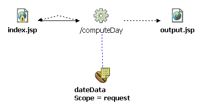
Figure 1 shows an example of a Web diagram that has one realized connection and three unrealized connections. The realized connection goes from the index.jsp Web page to the /computeDay action mapping. In this figure the connections use the default preferences for the visual representation of realized and unrealized connections.

Related concepts
Web diagram connectionsWeb diagrams and the Web diagram editor
Related tasks
Adding nodes to Web diagramsEditing Web diagrams - overview
Realizing connections in Web diagrams
Setting preferences for Web diagrams
Related reference
Resolution rules for realizing Web
diagram parts
Preferences for the Web diagram editor
Web diagram editor: pop-up menu