Guidelines: Statechart Diagram
Topics
- Explanation
- States
- Transitions
- Substates
- History states
- Common modeling techniques
- Hints and tips
- Designing with abstract state machines
- Chain states
Explanation

State machines are used to model the dynamic behavior of a model element, and more specifically, the event-driven aspects of the system's behavior (see Concepts: Events and Signals). State machines are specifically used to define state-dependent behavior, or behavior that varies depending on the state in which the model element is in. Model elements whose behavior does not vary with its state of the element do not require state machines to describe their behavior (these elements are typically passive classes whose primary responsible is to manage data). In particular, state machines must be used to model the behavior of active classes that use call events and signal events to implement their operations (as transitions in the class's state machine).
A state machine consists of states, linked by transitions. A state is a condition of an object in which it performs some activity or waits for an event. A transition is a relationship between two states which is triggered by some event, which performs certain actions or evaluations, and which results in a specific end-state. The elements of a state machine are depicted in Figure 1.
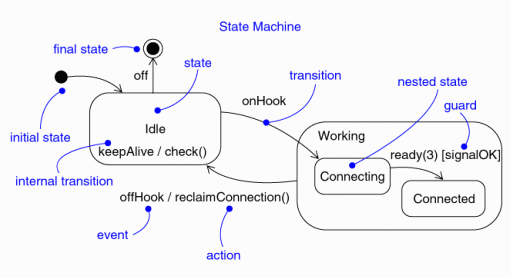
Figure 1. State machine notation.
A simple editor can be viewed as a finite state machine with the states Empty, Waiting for a command, and Waiting for text. The events Load file, Insert text, Insert character, and Save and quit cause transitions in the state machine. The state machine for the editor is depicted in Figure 1 below.

Figure 2. The state machine for a simple editor.
States

A state is a condition of an object in which it performs some activity or waits for an event. An object may remain in a state for a finite amount of time. A state has several properties:
| Name | A textual string which distinguishes the state from other states; a state may also be anonymous, meaning that it has no name. |
|---|---|
| Entry/exit actions | Actions executed on entering and exiting the state. |
| Internal transitions | Transitions that are handled without causing a change in state. |
| Substates | The nested structure of a state, involving disjoint (sequentially active) or concurrent (concurrently active) substates. |
| Deferred events | A list of events that are not handled in that state but are postponed and queued for handling by the object in another state. |
As depicted in Figure 1, there are two special states that may be defined for an object's state machine. The initial state indicates the default starting place for the state machine or substate. An initial state is depicted as a filled black circle. The final state indicates the completion of the execution of the state machine or that the enclosing state has been completed. A final state is represented as a filled black circle surrounded by an unfilled circle. Initial and final states are really pseudostates. Neither may have the usual parts of a normal state, except for a name. A transition from an initial state to a final state may have the full complement of features, including a guard condition and an action, but may not have a trigger event.
Transitions

A transition is a relationship between two states indicating that an object in the first state will perform certain actions and enter a second state when a specified event occurs and specified conditions are satisfied. On such a change of state, the transition is said to 'fire'. Until the transition fires, the object is said to be in the 'source' state; after it fires, it is said to be in the 'target' state. A transition has several properties:
| Source state | The state affected by the transition; if an object is in the source state, an outgoing transition may fire when the object receives the trigger event of the transition and if the guard condition, if any, is satisfied. |
|---|---|
| Event trigger | The event that makes the transition eligible to fire (providing its guard condition is satisfied) when received by the object in the source state. |
| Guard condition | A boolean expression that is evaluated when the transition is triggered by the reception of the event trigger; if the expression evaluates True, the transition is eligible to fire; if the expression evaluates to False, the transition does not fire. If there is no other transition that could be triggered by the same event, the event is lost. |
| Action | An executable atomic computation that may directly act upon the object that owns the state machine, and indirectly on other objects that are visible to the object. |
| Target state | The state that is active after the completion of the transition. |
A transition may have multiple sources, in which case it represents a join from multiple concurrent states, as well as multiple targets, in which case it represents a fork to multiple concurrent states.
Event Triggers
In the context of the state machine, an event is an occurrence of a stimulus that can trigger a state transition. Events may include signal events, call events, the passing of time, or a change in state. A signal or call may have parameters whose values are available to the transition, including expressions for the guard conditions and action. It is also possible to have a triggerless transition, represented by a transition with no event trigger. These transitions, also called completion transitions, is triggered implicitly when its source state has completed its activity.
Guard Conditions
A guard condition is evaluated after the trigger event for the transition occurs. It is possible to have multiple transitions from the same source state and with the same event trigger, as long as the guard conditions don't overlap. A guard condition is evaluated just once for the transition at the time the event occurs. The boolean expression may reference the state of the object.
Actions
An action is an executable atomic computation, meaning that it cannot be interrupted by an event and therefore runs to completion. This is in contrast to an activity, which may be interrupted by other events. Actions may include operation calls (to the owner of the state machine as well as other visible objects), the creation or destruction of another object, or the sending of a signal to another object. In the case of sending a signal, the signal name is prefixed with the keyword 'send'.
Entry and Exit Actions
Entry and exit actions allow the same action to be dispatched every time the state is entered or left, respectively. Entry and exit actions enable this to be done cleanly, without having to explicitly put the actions on every incoming or outgoing transition explicitly. Entry and exit actions may not have arguments or guard conditions. The entry actions at the top-level of a state machine for a model element may have parameters representing the arguments that the machine receives when the element is created.
Internal Transitions
Internal transitions allow events to be handled within the state without leaving the state, thereby avoiding triggering entry or exit actions. Internal transitions may have events with parameters and guard conditions, and essentially represent interrupt-handlers.
Deferred Events
Deferred events are those whose handling is postponed until a state in which the event is not deferred becomes active. When this state becomes active, the event occurrence is triggered and may cause transitions as if it had just occurred. The implementation of deferred events requires the presence of an internal queue of events. If an event occurs but is listed as deferred, it is queued. Events are taken off this queue as soon as the object enters a state that does not defer these events.
Substates

A simple state is one which has no substructure. A state which has substates (nested states) is called a composite state. Substates may be nested to any level. A nested state machine may have at most one initial state and one final state. Substates are used to simplify complex flat state machines by showing that some states are only possible within a particular context (the enclosing state).
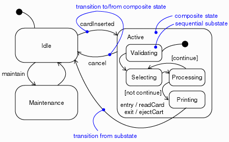
Figure 3. Substates.
From a source outside an enclosing composite state, a transition may target the composite state or it may target a substate. If its target is the composite state, the nested state machine must include an initial state, to which control passes after entering the composite state and after dispatching its entry action (if any). If its target is the nested state, control passes to the nested state after dispatching the entry action of the composite state (if any), and then the entry action of the nested state (if any).
A transition leading out of a composite state may have as its source the composite state or a substate. In either case, control first leaves the nested state (and its exit action, if any, is dispatched), then it leaves the composite state (and its exit action, if any, is dispatched). A transition whose source is the composite state essentially interrupts the activity of the nested state machine.
History States

Unless otherwise specified, when a transition enters a composite state, the action of the nested state machine starts over again at the initial state (unless the transition targets a substate directly). History states allow the state machine to re-enter the last substate that was active prior to leaving the composite state. An example of history state usage is presented in Figure 3.
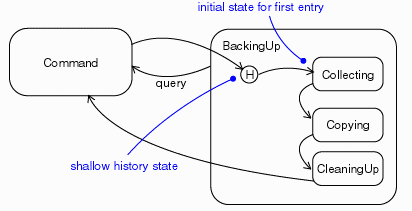
Figure 4. History State.
Common Modeling Techniques

State machines are used most commonly to model the behavior of an object across its lifetime. They are particularly needed when objects have state-dependent behavior. Objects which may have state machines include classes, subsystems, use cases and interfaces (to assert states which must be satisfied by an object which realizes the interface).
Not all objects require state machines. If an object's behavior is simple, such that it simply store or retrieves data, the behavior of the object is state-invariant and its state machine is of little interest.
Modeling the lifetime of an object involves three things: specifying the events to which the object can respond, the response to those events, and the impact of the past on current behavior. Modeling the lifetime of an object also involves deciding the order in which the object can meaningfully respond to events, starting at the time of the object's creation and continuing until its destruction.
To model the lifetime of an object:
- Set the context for the state machine, whether it is a class, a use case,
or the system as a whole.
- If the context is a class or a use case, collect the neighboring classes, including parent classes or classes reachable by associations or dependencies. These neighbors are candidate targets for actions and are candidate targets for inclusion in guard conditions.
- If the context is the system as a whole, narrow your focus to one behavior of the system, and then consider the lifetimes of the objects involved in that aspect. The lifetime of the entire system is simply too big too be a meaningful focus.
- Establish initial and final states for the object. If there are preconditions or postconditions of the initial and final states, define those as well.
- Determine the events to which the object responds. These can be found in the object's interfaces.
- Starting from the initial state to the final state, lay-out the top-level states the object may be in. Connect these states with transitions triggered by the appropriate events. Continue by adding these transitions.
- Identify any entry or exit actions.
- Expand or simplify the state machine by using substates.
- Check that all events triggering transitions in the state machine match events expected by the interfaces realized by the object. Similarly, check that all events expected by the interfaces of the object are handled by the state machine. you explicitly want to ignore events (e.g. deferred events).
- Check that all actions in the state machine are supported by relationships, methods, and operations of the enclosing object.
- Trace through the state machine, comparing it with expected sequences of events and their responses. Search for unreachable states and states in which the machine gets stuck.
- If you re-arrange or re-structure the state machine, check to make sure that the semantics have not changed.
Hints and Tips

- When given a choice, use the visual semantics of the state machine rather than writing detail transition code. For example, do not trigger one transition on several signals, then use detail code to manage the flow of control differently depending on the signal. Use separate transitions, triggered by separate signals. Avoid conditional logic in transition code that hides additional behavior.
- Name states according to what you are waiting for or what is happening during the state. Remember that a state is not a 'point in time'; it's a period during which the state machine is waiting for something to happen. For example, 'waitingForEnd' is a better name than 'end'; 'timingSomeActivity' is better than 'timeout'. Do not name states as if they were actions.
- Name all states and transitions within a state machine uniquely; this will make source-level debugging easier.
- Use state variables (attributes used to control behavior) cautiously; do not use them in lieu of creating new states. Where states are few, with little or no state-dependent behavior, and where there is little or no behavior that might be concurrent with or independent of the object containing the state machine, state variables may be used. If there is complex, state-dependent behavior which is potentially concurrent, or if events which must be handled may originate outside the object containing the state machine, consider using a collaboration of two or more active objects (possibly defined as a composition).
- If there are more than 5 ± 2 states on a single diagram, consider using substates. Common sense applies: ten states in an absolutely regular pattern might be fine, but two states with forty transitions between them obviously needs to be re-thought. Make sure the state machine is understandable.
- Name transitions for what triggers the event and/or what happens during the transition. Choose names that improve understandability.
- When you see a choice vertex, you should ask whether you can delegate the responsibility for that choice to another component, such that it gets presented to the object as a distinct set of signals to be acted upon (e.g., instead of a choice on msg->data > x), have the sender or some other intermediate actor make the decision and send a signal with the decision explicit in the signal name (e.g., use signals named isFull and isEmpty instead of having a signal named value and checking message data).
- Name the question answered at the choice vertex descriptively, e.g. 'isThereStillLife' or 'isItTimeToComplain'.
- Within any given object, try to keep choice vertex names unique (for the same reason as keeping transition names unique).
- Are there overly long code fragments on transitions? Should functions be used instead, and are common code fragments captured as functions? A transition should read like high-level pseudo-code, and should adhere to the same or even more stringent rules of length as C++ functions. For example, a transition with more than 25 lines of code is considered excessively long.
- Functions should be named by what they do.
- Pay particular attention to entry and exit actions: it is particularly easy to make changes and forget to change the entry and exit actions.
- Exit actions can be used to provide safety features, e.g. the exit action from the 'heaterOn' state turns the heater off, where the actions are used to enforce an assertion.
- Generally substates should contain two or more states unless the state machine is abstract and will be refined by sub-classes of the enclosing element.
- Choice points should be used in lieu of conditional logic in actions or transitions. Choice point are easily seen, whereas conditional logic in code is hidden from view and easy to overlook.
- Avoid guard conditions
- If the event triggers several transitions, there is no control over which guard condition is evaluated first. As a result, results can be unpredictable.
- More than one guard condition could be 'true', but only one transition can be followed. The path chosen can be unpredictable.
- Guard conditions are non-visual; it is harder to 'see' their presence.
- Avoid state machines which resemble flow charts.
- This may indicate an attempt to model an abstraction that is not really
there, such as:
- using an active class to model behavior that is best suited for a passive (or data) class or
- modeling a data class by using a data class and an active class that are very tightly coupled (i.e. the data class was used for passing type information around but the active class contains most of the data that should be associated with the data class).
- This misuse of state machines can be recognized by the following symptoms:
- messages sent to 'self', primarily just to re-use code
- few states, with many choice points
- in some cases a state machine without cycles. Such state machines are valid in process control applications or when trying to control a sequence of events; their presence during analysis usually represents the degeneration of the state machine into a flow chart.
- When the problem is identified:
- Consider splitting the active class into smaller units with more distinct responsibilities,
- Move more behavior into a data class that is associated with the problem active class.
- Move more behavior into active class functions.
- Make more meaningful signals instead of relying on data.
- This may indicate an attempt to model an abstraction that is not really
there, such as:
Designing with
Abstract State Machines

An abstract state machine is a state machine that needs to have more detail added before it can be used for practical purposes. Abstract state machines can be used to define generic, reusable behavior which is further refined in subsequent model elements.
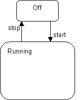
Figure 5. An abstract state machine.
Consider the abstract state machine in Figure 5. The simple state machine depicted is representative of the most abstract level of behavior (the "control" automaton) of many different types of elements in event-driven systems. Although they all share this high-level form, the different element types may have widely different detailed behaviors in the Running state depending on their purpose. Therefore, this state machine would most likely be defined in some abstract class that serves as the root class for the different specialized active classes
Let us therefore define two such different refinements of this abstract state machine, using inheritance. These two refinements, R1 and R2, are shown in Figure 6. For clarity, we have drawn the elements inherited from the parent class using a gray pen.
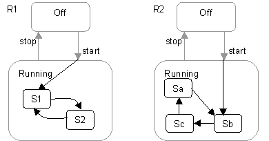
Figure 6. Two refinements of the state machine in Figure 5.
The two refinements clearly differ in how they decompose the Running state and also how they extend the original "start" transition. These choices can only be made, of course, once the refinement is known and, hence, could not have been done with a single end-to-end transition in the abstract class.
Chain States

The ability to "continue" both incoming transitions and outgoing transitions is fundamental for the type of refinement described above. It may seem that entry points and final states, combined with continuation transitions are sufficient to provide these semantics. Unfortunately, this is not sufficient when there are multiple different transitions that need to be extended.
What is required for the abstract behavior pattern is a way of chaining two or more transition segments that are all executed in the scope of a single run-to-completion step. This means that transitions entering a hierarchical state are split into the incoming part that effectively terminates on the state boundary and an extension that continues within the state. Similarly, outgoing transitions emanating from a hierarchically nested state are segmented into a part that terminates on the enclosing state boundary and a part that continues from the state boundary to the target state. This effect can be achieved in UML with the introduction the chain state concept. This is modeled by a stereotype (<<chainState>>) of the UML State concept. This is a state whose only purpose is to "chain" further automatic (triggerless) transitions onto an input transition. A chain state has no internal structure-no entry action, no internal activity, no exit action. It also has no transitions triggered by events. It may have any number of input transitions. It may have an outgoing transition with no trigger event; this transition automatically fires when an input transition activates the state. The purpose of the state is to chain an input transition to a separate output transition. Between the input transition(s) and the chained output transition, one connects to another state inside the containing state and the other connects to another state outside the containing state. The purpose of introducing a chain state is to separate the internal specification of the containing state from its external environment; it is a matter of encapsulation.
In effect, a chain state represents a "pass through" state that serves to chain a transition to a specific continuation transition. If no continuation transition is defined, then the transition terminates in the chain state, and some transition on an enclosing state must eventually fire to move things along.
The example state machine segment in Figure 7 illustrates chain states and their notation. Chain states are represented in a state machine diagram by small white circles located within the appropriate hierarchical state (this notation is similar to initial and final states, which they resemble). The circles are stereotype icons of the chain state stereotype and are usually drawn near to the boundary for convenience. (In fact, a notational variation would be to draw these on the border of the enclosing state.)
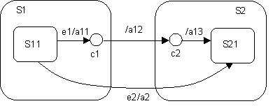
Figure 7. Chain states and chained transitions.
The chained transition in this example consists of the three chained transition segments e1/a11-/a12-/a13. When signal e1 is received, the transition labeled e1/a11 is taken, its action a11 executed, and then chain state c1 is reached. After that, the continuation transition between c1 and c2 is taken, and finally, since c2 is also a chain state, the transition from c2 to S21. If the states along these paths all have exit and entry actions, the actual sequence of action executions proceeds as follows:
- exit action of S11
- action a11
- exit action of S1
- action a12
- entry action of S2
- action a13
- entry action of S21
All of this is executed in the scope of a single run-to-completion step.
This should be compared against the action execution semantics of the direct transition e2/a2, which are:
- exit action of S11
- exit action of S1
- action a2
- entry action for state S2
- entry action for state S21
