Guidelines: Identifying Enterprise JavaBeans (EJBs)
Topics
Introduction

This guideline focuses on identifying EJBs. Additional guidance on EJBs is provided in Guidelines: EJBs.
Identifying EJBs

Typically EJBs are used to implement a server-side business object that requires support for transactions, security, and remote access, or that operates on shared data (such as updating account information).
EJBs are often identified when design classes are identified from Analysis Classes. Control classes are good candidates for session beans, as session beans are geared for providing control logic. Entity classes are good candidates for entity beans, as entity beans are geared to persistent data.
Also refer to the following more specific guidelines:
Comparing
Session, Message-Driven, and Entity beans

Summarizing some of the guidelines previously mentioned, this table identifies the roles played by the different EJBs, how they're accessed, and the nature of their state.
| Session | Message-Driven | Entity | |
|---|---|---|---|
|
Role |
Implement client-specific business logic |
Implements message processing-specific business logic |
Implement business entity-specific business logic |
|
Access method |
Single client through local or remote interfaces |
Container through JMS MessageListener interface; not directly accessible by clients |
Many simultaneous clients through local and remote interfaces |
|
State |
Transient conversational state between client and container can be maintained |
Stateless, but can maintain handles to resources in instance |
Persistent state saved to database |
Modeling EJBs

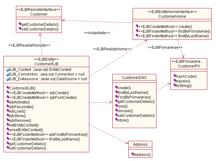
EJBs are modeled as a set of stereotyped classes. Specifically, the bean class and any EJB interface classes. EJB interfaces are modeled as stereotyped classes, not UML interfaces, for reasons discussed in Guidelines: Interfaces for J2EE Applications.
The relationships between the bean class and the EJB interfaces are modeled as dependencies from the bean class to the interfaces, and not as realizes relationships. Typically, the Java implements construct is represented as a realization between an interface and a class. However, EJB classes do not implement their interface classes, and so a dependency is more appropriate. The following diagram shows an example. For more on this particular example, refer to Guidelines: Designing Subsystems for J2EE Applications.

Example EJB and Helper Classes
The following are the UML stereotypes applicable to modeling EJBs.
| Stereotype | Applies To | Definition |
|---|---|---|
|
<<EJBSessionHomeInterface>> | Class | Indicates a session or entity home interface respectively. |
| <<EJBRemoteInterface>> | Class | Indicates an EJB remote interface. |
| <<EJBLocalInterface>> | Class | Indicates an EJB local interface. |
| <<EJBSession>> | Class | Indicates an EJB session bean class. |
| <<EJBEntity>> | Class | Indicates an EJB entity bean class. |
| <<EJBMessageDriven>> | Class | Indicates that the class is a message-driven bean. |
An EJB is typically grouped in a subsystem, along with closely related classes and EJBs. This allows the designer to provide a specification view of EJBs independent from their implementation, and to group with other design elements to provide a higher level abstraction. See Guidelines: Designing Subsystems for J2EE Applications for some additional details.
Also refer to the UML/EJB Mapping Specification (RSC01) for a complete list of stereotypes for representing EJB constructs.
Modeling Message-Driven Beans

Model dependencies to the topics or queues that the message-driven bean subscribes to. See Guidelines: Describing the Run-Time Architecture for J2EE Applications for more guidance on modeling concurrent elements in a J2EE Application.
Modeling EJB Properties

The use of mechanisms, such as container-managed persistency, transactions, authorization, and so on, can be modeled as additional properties of the bean class, or simply included in a textual description associated with the bean class.
Use sequence diagrams to consider scenarios that use these mechanisms.
Modeling EJB Object Interactions

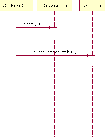
Interaction diagrams (collaboration and sequence diagrams) can be used to show the dynamic behavior of EJBs and the interaction of non-EJBs (including Web components and external client applications) with EJBs.
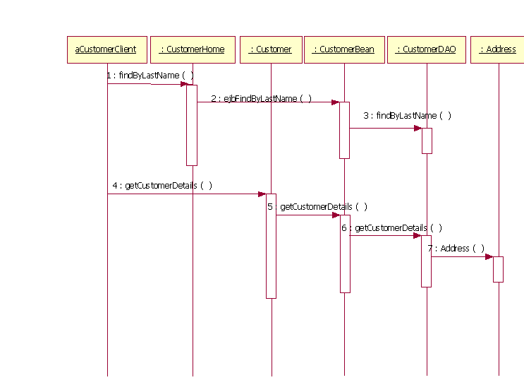
These interaction diagrams are essentially the same as described in Activity: Use-Case Design. Interactions can be shown with the bean as a black box, by interacting only with the EJB interfaces. Interactions might also show the bean implementation by showing interactions between the EJB interfaces and the bean implementation class. Note that intervening interaction with the container is generally not shown.
Message-driven beans consume messages that arrive asynchronously from other sources. You could choose to show an asynchronous message flowing from producer to consumer directly, or you might model the relationship more precisely by modeling topics and queues.
An example of a sequence diagram showing an interaction of a client class with EJB interfaces is shown in Figure 2.

Figure 2: Interaction of a Client Class with EJB Interfaces
Figure 3 is a sequence diagram similar to Figure 2, but shows interactions with the bean implementation.

Figure 3: Example of an Interaction with an EJB Implementation
Modeling Alternatives

The EJB, as a grouping of a bean implementation class plus EJB interfaces, can also be modeled as a subsystem or component.
Some designers may also choose to model an EJB as a class, and stereotype the operations to indicate if they belong to the "local", "remote", or "home" interfaces. This provides a more compact notation than the other alternatives.
