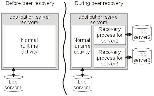
This topic describes peer recovery, which enables any server in a cluster to recover the transactional work for any other server in the same cluster.
As a vital part of providing recovery for transactions, the transaction service logs information about active transactional work, such that the information is preserved across a server crash. This means that any transactional work in progress at the time of a server failure can be resolved when the server is restarted.
The standard recovery process performed when an application server restarts is for the server to retrieve and process the logged transaction information, to recover transactional work and complete in-doubt transactions. Completion of the transactional work (and hence the release of any database locks held by the transactions) is delayed until the server has successfully restarted and processed its transaction logs. If the server is slow to recover or requires manual intervention, the transactional work cannot be completed and access to associated databases is disrupted.
To minimize such disruption to transactional work and the associated databases, WebSphere Application Server provides a high availability strategy known as transaction peer recovery .
Peer recovery is provided within a server cluster. Each server in the cluster has a recovery process that can run alongside normal server activity, and enables a server in the cluster to recover the transactional work for another server in the same cluster. There is no need to start a new application server specifically to recover the failed server.

The peer recovery process is the logical equivalent to restarting the failed server, but does not constitute a complete restart of the failed server within the peer server. It merely provides an opportunity for outstanding work to be completed. It is not possible for the peer recovery process to start new work beyond recovery processing. In other words, no "forward processing" is possible for the failed server. Both transactions and the compensation service fail over together to the same peer server.
Peer recovery moves the high availability requirements away from individual servers and onto the server cluster. After such failures, the WLM system of the cluster dispatches new work onto the remaining servers, the only difference from the users perspective being the potential drop in overall system throughput. If a server fails, all that is required is to tidy up work that was active on the failed server and redirect requests to an alternate server. Both transactions and the compensation service fail over together to the same peer server.
Common configuration for peer recovery
The transaction service requires a common configuration in order to be able to perform peer recovery between servers. This means that peer recovery processing can only take place between members of the same server cluster. Although a cluster can contain both version 5 and version 6 servers, peer recovery can only be performed between servers in the cluster that are at version 6 or later.
Control over which server is nominated to perform recovery processing for a failed peer is handled by the selected Clustered TM Policy of the cluster's core group. The default "1 of N with preferred server" policy nominates a running member of the cluster to perform peer recovery processing and passes recovery control back to the failed server when it restarts.
By default, peer recovery is disabled until the Enable high availability for persistent services check box in the cluster configuration is selected. When this option has been selected, cluster members must be restarted before they engage in peer recovery processing for other cluster members. Similarly, if this option is disabled, cluster members must be restarted to prevent them from performing peer recovery.
For more information about high availability and core groups, see High availability groups and Core groups.
Location of recovery log files
The storage mechanism used to host recovery log files (for example, you can use IBM NAS and shared SCSI drives, but not simple network share) and access to that mechanism (for example, through a LAN), must support the file-based force operation that is used by the recovery log service to force data to disk. After the force operation is complete, information must be persistently stored on physical disk media; for example, IBM NAS (http://www.ibm.com/servers/storage/nas/index.html).
Interactions between the HA framework and the recovery log service must prevent concurrent access to a single physical recovery log.
Recovery log directory administration and scripting
You can configure the location of the transaction log directory using either the WebSphere administrative console or commands. For peer recovery, the configuration is stored as part of the recovery log configuration in the serverindex.xml node-level configuration file. To ease migration of the transaction log configuration from previous versions of WebSphere Application Server, special logic has been added to the administrative console. This is to help migration of the transaction log directory configuration from the original server.xml server-level configuration file to the serverindex.xml node-level configuration file.
Peer recovery example
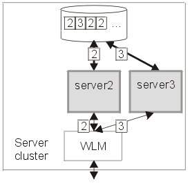
The following diagrams illustrates the peer recovery process that takes place if a single server fails. Figure 1 shows three stable servers running in a WAS cluster. The WLM engine is load balancing work between these servers which results in locks being held by the backend database on behalf of each of them. In addition, communication has taken place between servers 1 and 2 which now retain references to each other.
Figure 1.
Server cluster up and running, just before server failure
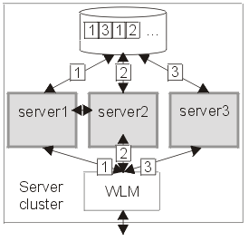
Figure 2 shows the state of the system after server 1 has failed without clearing locks from database. Servers 2 and 3 were able to run their existing transactions to completion and release existing locks in the backend database, but further access may be impaired because of the locks still held on behalf of server 1. In practice, some level of access by servers 2 and 3 should still be possible, assuming appropriately configured lock granularity, but for this example assume that servers 2 and 3 have attempted to access locked records and become blocked.
Figure 2.
Figure 2 -
Server 1 fails. Servers 2 and 3 become blocked as a result.
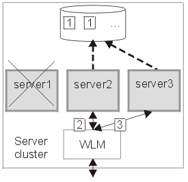
Figure 3 shows a peer recovery process for server 1 running inside server 3. The transaction service portion of the recovery process retrieves the information persisted by server 1, and uses that information to complete any in-doubt transactions. In addition, the cluster redirects endpoint references for server 1 to server 3. In this figure, the peer recovery process is partially complete as some locks are still held by the database on behalf of server 1.
Figure 3.
Figure 3 - Peer recovery process started in server 3
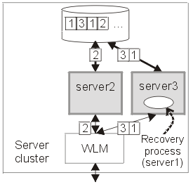
Figure 4 shows the state of the server cluster when the peer recovery process has completed. The system is in a stable state with just two servers, between which the WLM engine can balance workload. Server 1 can be restarted at some time in the future, when it will have no recovery processing of its own to perform.
Figure 4.
Figure 4 - Server cluster stable again with just two servers - server 2 and server 3.
Related concepts
Core groups
High availability groups
Related tasks
Configuring transaction properties for an application server